

GORMAN-RUPP PUMPS 10 Series, 13E52-CH13, 13E52-CH13 S/G Installation, Operation And Maintenance Manual
Page 1
ACDEU
OM-04733-02
November 18, 2005
INSTALLATION, OPERATION,
AND MAINTENANCE MANUAL
WITH PARTS LIST
10 SERIES PUMPS
MODELS
13E52−CH13
13E52−CH13 S/G
THE GORMAN-RUPP COMPANY D MANSFIELD, OHIO
www.grpumps.com
GORMAN-RUPP OF CANADA LIMITED D ST. THOMAS, ONTARIO, CANADA Printed in U.S.A.
eCopyright by the Gorman-Rupp Company
Page 2
Register your new
Gorman-Rupp pump online at
www.grpumps.com/register.
Valid serial number and e-mail address required.
The engine exhaust from this
product contains chemicals
known to the State of California to
cause cancer, birth defects or
other reproductive harm.
RECORD YOUR PUMP MODEL AND SERIAL NUMBER
Please record your pump model and serial number in the
spaces provided below. Your Gorman-Rupp distributor
needs this information when you require parts or service.
Pump Model:
Serial Number:
Page 3

TABLE OF CONTENTS
INTRODUCTION PAGE I − 1. . . . . . . . . . . . . . . . . . . . . . . . . . . . . . . . . . . . . . . . . . . . . . . . .
SAFETY - SECTION A PAGE A − 1. . . . . . . . . . . . . . . . . . . . . . . . . . . . . . . . . . . . . . . . . . . .
INSTALLATION − SECTION B PAGE B − 1. . . . . . . . . . . . . . . . . . . . . . . . . . . . . . . . . . . .
Pump Dimensions PAGE B − 1. . . . . . . . . . . . . . . . . . . . . . . . . . . . . . . . . . . . . . . . . . . . . . . . . . . . .
PREINSTALLATION INSPECTION PAGE B − 1. . . . . . . . . . . . . . . . . . . . . . . . . . . . . . . . . . . . . . . . . . . .
Battery Specifications And Installation PAGE B − 2. . . . . . . . . . . . . . . . . . . . . . . . . . . . . . . . . . . .
POSITIONING PUMP PAGE B − 2. . . . . . . . . . . . . . . . . . . . . . . . . . . . . . . . . . . . . . . . . . . . . . . . . . . . . . .
Lifting PAGE B − 2. . . . . . . . . . . . . . . . . . . . . . . . . . . . . . . . . . . . . . . . . . . . . . . . . . . . . . . . . . . . . . . . .
Mounting PAGE B − 3. . . . . . . . . . . . . . . . . . . . . . . . . . . . . . . . . . . . . . . . . . . . . . . . . . . . . . . . . . . . .
Clearance PAGE B − 3. . . . . . . . . . . . . . . . . . . . . . . . . . . . . . . . . . . . . . . . . . . . . . . . . . . . . . . . . . . . .
SUCTION AND DISCHARGE PIPING PAGE B − 3. . . . . . . . . . . . . . . . . . . . . . . . . . . . . . . . . . . . . . . . .
Materials PAGE B − 3. . . . . . . . . . . . . . . . . . . . . . . . . . . . . . . . . . . . . . . . . . . . . . . . . . . . . . . . . . . . . .
Line Configuration PAGE B − 3. . . . . . . . . . . . . . . . . . . . . . . . . . . . . . . . . . . . . . . . . . . . . . . . . . . . . .
Connections to Pump PAGE B − 3. . . . . . . . . . . . . . . . . . . . . . . . . . . . . . . . . . . . . . . . . . . . . . . . . .
Gauges PAGE B − 3. . . . . . . . . . . . . . . . . . . . . . . . . . . . . . . . . . . . . . . . . . . . . . . . . . . . . . . . . . . . . . .
SUCTION LINES PAGE B − 3. . . . . . . . . . . . . . . . . . . . . . . . . . . . . . . . . . . . . . . . . . . . . . . . . . . . . . . . . . .
Fittings PAGE B − 4. . . . . . . . . . . . . . . . . . . . . . . . . . . . . . . . . . . . . . . . . . . . . . . . . . . . . . . . . . . . . . .
Strainers PAGE B − 4. . . . . . . . . . . . . . . . . . . . . . . . . . . . . . . . . . . . . . . . . . . . . . . . . . . . . . . . . . . . . .
Sealing PAGE B − 4. . . . . . . . . . . . . . . . . . . . . . . . . . . . . . . . . . . . . . . . . . . . . . . . . . . . . . . . . . . . . . .
Suction Lines In Sumps PAGE B − 4. . . . . . . . . . . . . . . . . . . . . . . . . . . . . . . . . . . . . . . . . . . . . . . . .
Suction Line Positioning PAGE B − 4. . . . . . . . . . . . . . . . . . . . . . . . . . . . . . . . . . . . . . . . . . . . . . . .
DISCHARGE LINES PAGE B − 5. . . . . . . . . . . . . . . . . . . . . . . . . . . . . . . . . . . . . . . . . . . . . . . . . . . . . . . .
Siphoning PAGE B − 5. . . . . . . . . . . . . . . . . . . . . . . . . . . . . . . . . . . . . . . . . . . . . . . . . . . . . . . . . . . . .
Valves PAGE B − 5. . . . . . . . . . . . . . . . . . . . . . . . . . . . . . . . . . . . . . . . . . . . . . . . . . . . . . . . . . . . . . . .
Bypass Lines PAGE B − 5. . . . . . . . . . . . . . . . . . . . . . . . . . . . . . . . . . . . . . . . . . . . . . . . . . . . . . . . . .
OPERATION − SECTION C PAGE C − 1. . . . . . . . . . . . . . . . . . . . . . . . . . . . . . . . . . . . . .
PRIMING PAGE C − 1. . . . . . . . . . . . . . . . . . . . . . . . . . . . . . . . . . . . . . . . . . . . . . . . . . . . . . . . . . . . . . . . .
STARTING PAGE C − 1. . . . . . . . . . . . . . . . . . . . . . . . . . . . . . . . . . . . . . . . . . . . . . . . . . . . . . . . . . . . . . . .
OPERATION PAGE C − 1. . . . . . . . . . . . . . . . . . . . . . . . . . . . . . . . . . . . . . . . . . . . . . . . . . . . . . . . . . . . . .
Lines With a Bypass PAGE C − 2. . . . . . . . . . . . . . . . . . . . . . . . . . . . . . . . . . . . . . . . . . . . . . . . . . . .
Lines Without a Bypass PAGE C − 2. . . . . . . . . . . . . . . . . . . . . . . . . . . . . . . . . . . . . . . . . . . . . . . . .
Leakage PAGE C − 2. . . . . . . . . . . . . . . . . . . . . . . . . . . . . . . . . . . . . . . . . . . . . . . . . . . . . . . . . . . . . .
Liquid Temperature And Overheating PAGE C − 2. . . . . . . . . . . . . . . . . . . . . . . . . . . . . . . . . . . . .
Strainer Check PAGE C − 2. . . . . . . . . . . . . . . . . . . . . . . . . . . . . . . . . . . . . . . . . . . . . . . . . . . . . . . . .
Pump Vacuum Check PAGE C − 2. . . . . . . . . . . . . . . . . . . . . . . . . . . . . . . . . . . . . . . . . . . . . . . . . .
STOPPING PAGE C − 3. . . . . . . . . . . . . . . . . . . . . . . . . . . . . . . . . . . . . . . . . . . . . . . . . . . . . . . . . . . . . . . .
Cold Weather Preservation PAGE C − 3. . . . . . . . . . . . . . . . . . . . . . . . . . . . . . . . . . . . . . . . . . . . . .
TROUBLESHOOTING − SECTION D PAGE D − 1. . . . . . . . . . . . . . . . . . . . . . . . . . . . . .
PREVENTIVE MAINTENANCE PAGE D − 3. . . . . . . . . . . . . . . . . . . . . . . . . . . . . . . . . . . . . . . . . . . . . . .
PUMP MAINTENANCE AND REPAIR - SECTION E PAGE E − 1. . . . . . . . . . . . . . . . .
STANDARD PERFORMANCE CURVE PAGE E − 1. . . . . . . . . . . . . . . . . . . . . . . . . . . . . . . . . . . . . . . .
i
Page 4

TABLE OF CONTENTS
(continued)
PARTS LISTS:
Pump Model PAGE E − 3. . . . . . . . . . . . . . . . . . . . . . . . . . . . . . . . . . . . . . . . . . . . . . . . . . . . . . . . . .
Pump Model PAGE E − 5. . . . . . . . . . . . . . . . . . . . . . . . . . . . . . . . . . . . . . . . . . . . . . . . . . . . . . . . . .
Pump End Assy PAGE E − 7. . . . . . . . . . . . . . . . . . . . . . . . . . . . . . . . . . . . . . . . . . . . . . . . . . . . . . . .
PUMP AND SEAL DISASSEMBLY AND REASSEMBLY PAGE E − 8. . . . . . . . . . . . . . . . . . . . . . . . .
Suction Check Valve Disassembly PAGE E − 8. . . . . . . . . . . . . . . . . . . . . . . . . . . . . . . . . . . . . . . .
Back Cover Removal PAGE E − 8. . . . . . . . . . . . . . . . . . . . . . . . . . . . . . . . . . . . . . . . . . . . . . . . . . .
Pump Casing Removal PAGE E − 8. . . . . . . . . . . . . . . . . . . . . . . . . . . . . . . . . . . . . . . . . . . . . . . . .
Impeller Removal PAGE E − 9. . . . . . . . . . . . . . . . . . . . . . . . . . . . . . . . . . . . . . . . . . . . . . . . . . . . . .
Seal Removal and Disassembly PAGE E − 9. . . . . . . . . . . . . . . . . . . . . . . . . . . . . . . . . . . . . . . . . .
Seal Reassembly and Installation PAGE E − 9. . . . . . . . . . . . . . . . . . . . . . . . . . . . . . . . . . . . . . . .
Impeller Installation And Adjustment PAGE E − 10. . . . . . . . . . . . . . . . . . . . . . . . . . . . . . . . . . . . . .
Pump Casing Installation PAGE E − 11. . . . . . . . . . . . . . . . . . . . . . . . . . . . . . . . . . . . . . . . . . . . . . . .
Back Cover Installation PAGE E − 11. . . . . . . . . . . . . . . . . . . . . . . . . . . . . . . . . . . . . . . . . . . . . . . . .
Suction Check Valve Installation PAGE E − 11. . . . . . . . . . . . . . . . . . . . . . . . . . . . . . . . . . . . . . . . .
Final Pump Assembly PAGE E − 11. . . . . . . . . . . . . . . . . . . . . . . . . . . . . . . . . . . . . . . . . . . . . . . . . .
LUBRICATION PAGE E − 12. . . . . . . . . . . . . . . . . . . . . . . . . . . . . . . . . . . . . . . . . . . . . . . . . . . . . . . . . . . . .
Seal Assembly PAGE E − 12. . . . . . . . . . . . . . . . . . . . . . . . . . . . . . . . . . . . . . . . . . . . . . . . . . . . . . . . .
Engine PAGE E − 12. . . . . . . . . . . . . . . . . . . . . . . . . . . . . . . . . . . . . . . . . . . . . . . . . . . . . . . . . . . . . . . .
ii
Page 5
10 SERIES
OM−04733
INTRODUCTION
Thank You for purchasing a Gorman-Rupp pump.
Read this manual carefully to learn how to safely
install and operate your pump. Failure to do so
could result in personal injury or damage to the
pump.
This pump is a 10 Series, semi-open impeller, selfpriming centrifugal model with a suction check
valve. It is close-coupled to a single cylinder air
cooled Kohler gasoline engine. The pump is designed for handling dirty water containing specified entrained solids. The basic material of construction for wetted parts is gray iron with gray iron
impeller and steel wearing parts.
Because pump installations are seldom identical,
this manual cannot possibly provide detailed instructions and precautions for every aspect of
each specific application. Therefore, it is the responsibility of the owner/installer of the pump to
ensure that applications not addressed in this
manual are performed only after establishing that
neither operator safety nor pump integrity are compromised by the installation. Pumps and related
equipment must be installed and operated according to all national, local and industry standards.
For information or technical assistance on the
power source, contact the power source manufacturer’s local dealer or representative.
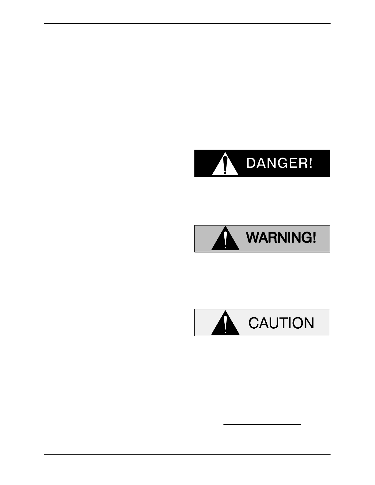
The following are used to alert maintenance personnel to procedures which require special attention, to those which could damage equipment, and
to those which could be dangerous to personnel:
Immediate hazards which WILL result in
severe personal injury or death. These
instructions describe the procedure required and the injury which will result
from failure to follow the procedure.
Hazards or unsafe practices which
COULD result in severe personal injury
or death. These instructions describe
the procedure required and the injury
which could result from failure to follow
the procedure.
If there are any questions regarding the pump or its
application which are not covered in this manual or
in other literature accompanying this unit, please
contact your Gorman-Rupp distributor, or:
The Gorman-Rupp Company
P.O. Box 1217
Mansfield, Ohio 44901−1217
Phone: (419) 755−1011
or:
Gorman-Rupp of Canada Limited
70 Burwell Road
St. Thomas, Ontario N5P 3R7
Phone: (519) 631−2870
Hazards or unsafe practices which COULD
result in minor personal injury or product
or property damage. These instructions
describe the requirements and the possible damage which could result from failure
to follow the procedure.
NOTE
Instructions to aid in installation, operation, and
maintenance or which clarify a procedure.
PAGE I − 1INTRODUCTION
Page 6
10 SERIES
OM−04733
SAFETY − SECTION A
This information applies to 10 Series engine driven pumps. Refer to the manual
accompanying the engine before attempting to begin operation.
This manual will alert personnel to
known procedures which require special attention, to those which could
damage equipment, and to those which
could be dangerous to personnel. However, this manual cannot possibly anticipate and provide detailed instructions
and precautions for every situation that
might occur during maintenance of the
unit. Therefore, it is the responsibility of
the owner/maintenance personnel to
ensure that only safe, established maintenance procedures are used, and that
any procedures not addressed in this
manual are performed only after establishing that neither personal safety nor
pump integrity are compromised by
such practices.
6. Vent the pump slowly and cautiously.
7. Drain the pump.
This pump is designed to handle dirty
water containing specified entrained
solids. Do not attempt to pump volatile,
corrosive, or flammable liquids which
may damage the pump or endanger personnel as a result of pump failure.
Use lifting and moving equipment in
good repair and with adequate capacity
to prevent injuries to personnel or damage to equipment. The bail is intended
for use in lifting the pump assembly
only. Suction and discharge hoses and
piping must be removed from the pump
before lifting.
Before attempting to open or service the
pump:
1. Familiarize yourself with this manual.
2. Shut down the engine and disconnect the spark plug wire to ensure
that the pump will remain inoperative.
3. Allow the pump to completely cool
if overheated.
4. Check the temperature before
opening any covers, plates, or
plugs.
5. Close the suction and discharge
valves.
After the pump has been positioned,
make certain that the pump and all piping connections are tight, properly supported and secure before operation.
Do not operate the pump against a
closed discharge valve for long periods
of time. If operated against a closed discharge valve, pump components will
deteriorate, and the liquid could come
to a boil, build pressure, and cause the
pump casing to rupture or explode.
PAGE A − 1SAFETY
Page 7
Overheated pumps can cause severe
burns and injuries. If overheating of the
pump occurs:
1. Stop the pump immediately.
2. Ventilate the area.
3. Allow the pump to completely cool.
4. Check the temperature before
opening any covers, plates,
gauges, or plugs.
5. Vent the pump slowly and cautiously.
6. Refer to instructions in this manual
before restarting the pump.
10 SERIESOM−04733
engine in an explosive atmosphere.
When operating internal combustion
engines in an enclosed area, make certain that exhaust fumes are piped to the
outside. These fumes contain carbon
monoxide, a deadly gas that is colorless, tasteless, and odorless.
Fuel used by internal combustion engines presents an extreme explosion
and fire hazard. Make certain that all
fuel lines are securely connected and
free of leaks. Never refuel a hot or running engine. Avoid overfilling the fuel
tank. Always use the correct type of fuel.
Do not remove plates, covers, gauges,
pipe plugs, or fittings from an overheated pump. Vapor pressure within the
pump can cause parts being disengaged to be ejected with great force. Allow the pump to completely cool before
servicing.
Do not operate an internal combustion
Never tamper with the governor to gain
more power. The governor establishes
safe operating limits that should not be
exceeded. The maximum continuous
operating speed for this pump is 3100
RPM.
Pumps and related equipment must be installed and operated according to all national, local and industry standards.
PAGE A − 2 SAFETY
Page 8

10 SERIES OM−04733
INSTALLATION − SECTION B
Review all SAFETY information in Section A.
Since pump installations are seldom identical, this
section offers only general recommendations and
practices required to inspect, position, and arrange the pump and piping.
Most of the information pertains to a standard
static lift application where the pump is positioned
above the free level of liquid to be pumped.
If installed in a flooded suction application where
the liquid is supplied to the pump under pressure,
some of the information such as mounting, line
configuration, and priming must be tailored to the
OUTLINE DRAWING
specific application. Since the pressure supplied
to the pump is critical to performance and safety,
be sure to limit the incoming pressure to 50% of the
maximum permissible operating pressure as
shown on the pump performance curve (see Section E, Page 1).
For further assistance, contact your Gorman-Rupp
distributor or the Gorman-Rupp Company.
Pump Dimensions
See Figure 1 for the approximate physical dimensions of the pump.
Figure 1. Pump Model 13E52−CH13 (Shown) And 13E52−CH13 S/G
PAGE B − 1INSTALLATION
Page 9
OM−04733 10 SERIES
PREINSTALLATION INSPECTION
The pump assembly was inspected and tested before shipment from the factory. Before installation,
inspect the pump for damage which may have occurred during shipment. Check as follows:
a. Inspect the pump and engine for cracks,
dents, damaged threads, and other obvious
damage.
b. Check for and tighten loose attaching hard-
ware. Since gaskets tend to shrink after drying, check for loose hardware at mating surfaces.
c. Carefully read all tags, decals, and markings
on the pump assembly, and perform all duties
indicated.
d. Check levels and lubricate as necessary. Re-
fer to LUBRICATION in the MAINTENANCE
AND REPAIR section of this manual and perform duties as instructed.
Battery Specifications And Installation
Unless otherwise specified on the pump order, the
engine battery for model 13E52−CH13 S/G was
not included with the unit. Refer to the following
specifications when selecting a battery.
Reserve
Capacity
@ 80_ F
(Minutes)
41
Amp/
Hr.
Rating
33
Approx.
Overall
Dims.
(Inches)
7.75L
x
5.13W
x
7.38H
Voltage
12 Volts
Cold
Crank
Amps
@ 0_ F
220−255
Table 1. Battery Specifications
Refer to the information accompanying the battery
and/or electrolyte solution for activation and charging instructions.
Before installing the battery, clean the positive and
negative cable connectors, and the battery terminals. Secure the battery by tightening the
holddown brackets. The terminals and clamps
may be coated with petroleum jelly to retard corrosion. Connect and tighten the positive cable first,
then the negative cable.
e. Check for the muffler and muffler guard
shipped loose with the pump.
f. Unless specified as an option on the original
order, the engine battery was not included
with the pump. If the battery was included on
the original pump order, it was shipped dry,
and electrolyte must be added before putting
the unit into service. Refer to Battery Specifi-
cations And Installation in this section for
details.
g. If the pump and engine have been stored for
more than 12 months, some of the components or lubricants may have exceeded their
maximum shelf life. These must be inspected
or replaced to ensure maximum pump service.
If the maximum shelf life has been exceeded, or if
anything appears to be abnormal, contact your
Gorman-Rupp distributor or the factory to determine the repair or updating policy. Do not put the
pump into service until appropriate action has
been taken.
POSITIONING PUMP
Use lifting and moving equipment in
good repair and with adequate capacity
to prevent injuries to personnel or damage to equipment. The bail is intended
for use in lifting the pump assembly
only. Suction and discharge hoses and
piping must be removed from the pump
before lifting.
Lifting
Pump unit weights will vary depending on the
mounting and drive provided. Check the shipping
tag on the unit packaging for the actual weight, and
use lifting equipment with appropriate capacity.
Drain the pump and remove all customer-installed
equipment such as suction and discharge hoses
or piping before attempting to lift existing, installed
units.
PAGE B − 2 INSTALLATION
Page 10
10 SERIES OM−04733
Materials
Either pipe or hose maybe used for suction and
discharge lines; however, the materials must be
The pump assembly can be seriously
damaged if the cables or chains used to lift
and move the unit are improperly wrapped
around the pump.
compatible with the liquid being pumped. If hose is
used in suction lines, it must be the rigid-wall, reinforced type to prevent collapse under suction. Using piping couplings in suction lines is not recommended.
Mounting
Locate the pump in an accessible place as close as
practical to the liquid being pumped. Level mounting is essential for proper operation.
The pump may have to be supported or shimmed
to provide for level operation or to eliminate vibration.
If the pump has been mounted on a movable base,
make certain the base is stationary by setting the
brake and blocking the wheels before attempting
to operate the pump.
To ensure sufficient lubrication and fuel supply to
the engine, do not position the pump and engine
more than 15_ off horizontal for continuous operation. The pump and engine may be positioned up
to 30_ off horizontal for intermittent operation
only; however, the engine manufacturer should be
consulted for continuous operation at angles
greater than 15_.
Line Configuration
Keep suction and discharge lines as straight as
possible to minimize friction losses. Make minimum use of elbows and fittings, which substantially increase friction loss. If elbows are necessary,
use the long-radius type to minimize friction loss.
Connections to Pump
Before tightening a connecting flange, align it exactly with the pump port. Never pull a pipe line into
place by tightening the flange bolts and/or couplings.
Lines near the pump must be independently supported to avoid strain on the pump which could
cause excessive vibration, decreased bearing life,
and increased shaft and seal wear. If hose-type
lines are used, they should have adequate support
to secure them when filled with liquid and under
pressure.
Clearance
When positioning the pump, allow a minimum
clearance of 18 inches (457,2 mm) in front of the
back cover to permit removal of the cover and easy
access to the pump interior.
SUCTION AND DISCHARGE PIPING
Pump performance is adversely effected by increased suction lift, discharge elevation, and friction losses. See the performance curve and notes
on Page E-1 to be sure your overall application allows pump to operate within the safe operation
range.
Gauges
Most pumps are drilled and tapped for installing
discharge pressure and vacuum suction gauges. If
these gauges are desired for pumps that are not
tapped, drill and tap the suction and discharge
lines not less than 18 inches (457,2 mm) from the
suction and discharge ports and install the lines.
Installation closer to the pump may result in erratic
readings.
SUCTION LINES
To avoid air pockets which could affect pump priming, the suction line must be as short and direct as
possible. When operation involves a suction lift, the
line must always slope upward to the pump from
PAGE B − 3INSTALLATION
Page 11
OM−04733 10 SERIES
the source of the liquid being pumped; if the line
slopes down to the pump at any point along the
suction run, air pockets will be created.
Fittings
Suction lines should be the same size as the pump
inlet. If reducers are used in suction lines, they
should be the eccentric type, and should be installed with the flat part of the reducers uppermost
to avoid creating air pockets. Valves are not normally used in suction lines, but if a valve is used,
install it with the stem horizontal to avoid air pockets.
Strainers
If a strainer is furnished with the pump, be certain
to use it; any spherical solids which pass through a
strainer furnished with the pump will also pass
through the pump itself.
If a strainer is not furnished with the pump, but is
installed by the pump user, make certain that the
total area of the openings in the strainer is at least
three or four times the cross section of the suction
line, and that the openings will not permit passage
of solids larger than the solids handling capability
of the pump.
This pump is designed to handle up to 2 inch (50,8
mm) diameter spherical solids.
Sealing
Suction Lines In Sumps
If a single suction line is installed in a sump, it
should be positioned away from the wall of the
sump at a distance equal to 1-1/2 times the diameter of the suction line.
If there is a liquid flow from an open pipe into the
sump, the flow should be kept away from the suction inlet because the inflow will carry air down into
the sump, and air entering the suction line will reduce pump efficiency.
If it is necessary to position inflow close to the suction inlet, install a baffle between the inflow and the
suction inlet at a distance 1-1/2 times the diameter
of the suction pipe. The baffle will allow entrained
air to escape from the liquid before it is drawn into
the suction inlet.
If two suction lines are installed in a single sump,
the flow paths may interact, reducing the efficiency
of one or both pumps. To avoid this, position the
suction inlets so that they are separated by a distance equal to at least 3 times the diameter of the
suction pipe.
Suction Line Positioning
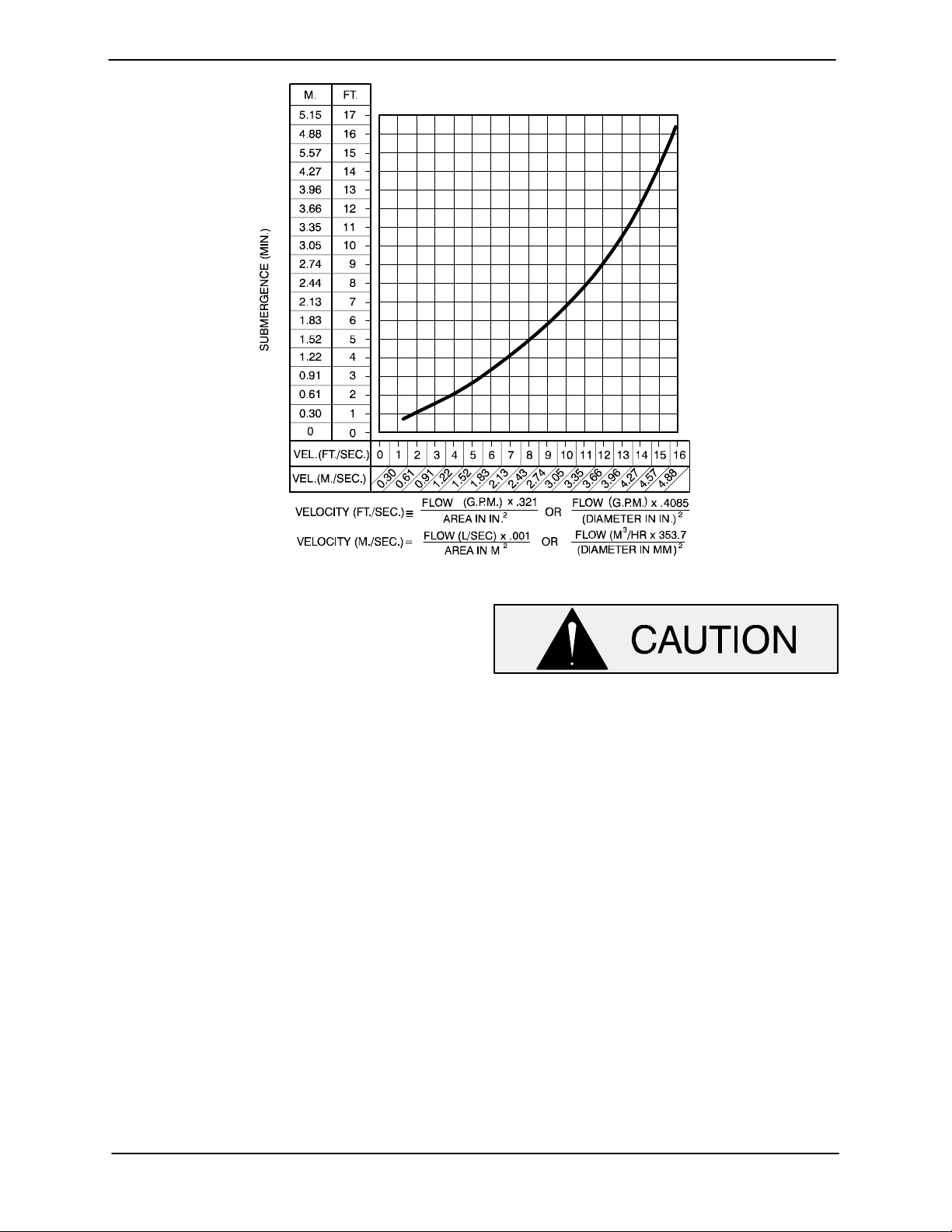
The depth of submergence of the suction line is
critical to efficient pump operation.
recommended minimum submergence vs. veloc-
ity.
Figure 2 shows
Since even a slight leak will affect priming, head,
and capacity, especially when operating with a
high suction lift, all connections in the suction line
should be sealed with pipe dope to ensure an airtight seal. Follow the sealant manufacturer’s recommendations when selecting and applying the
pipe dope. The pipe dope should be compatible
with the liquid being pumped.
PAGE B − 4 INSTALLATION
The pipe submergence required may be reduced
by installing a standard pipe increaser fitting at the
end of the suction line. The larger opening size will
reduce the inlet velocity. Calculate the required
submergence using the following formula based
on the increased opening size (area or diameter).
NOTE
Page 12
10 SERIES OM−04733
Figure 2. Recommended Minimum Suction Line Submergence vs. Velocity
DISCHARGE LINES
Siphoning
Do not terminate the discharge line at a level lower
than that of the liquid being pumped unless a siphon breaker is used in the line. Otherwise, a siphoning action causing damage to the pump
could result.
Valves
If a throttling valve is desired in the discharge line,
use a valve as large as the largest pipe to minimize
friction losses. Never install a throttling valve in a
suction line.
A check valve in the discharge line is normally recommended, but it is not necessary in low discharge head applications.
With high discharge heads, it is recommended that
a throttling valve and a system check valve be installed in the discharge line to protect the pump
from excessive shock pressure and reverse rotation when it is stopped.
If the application involves a high discharge
head, gradually close the discharge
throttling valve before stopping the pump.
Bypass Lines
If a system check valve is used due to high discharge head, it may be necessary to vent trapped
air from the top of the pump during the priming
process. This may be accomplished by installing a
bypass line from the top of the pump, back to the
source of liquid. The end of the bypass line must be
submerged. The line must be large enough to prevent clogging, but not so large as to affect pump
discharge capacity.
ALIGNMENT
The alignment of the pump and the engine is critical for trouble-free mechanical operation. See Section E, Securing Pump And Intermediate To En-
gine for detailed information.
PAGE B − 5INSTALLATION
Page 13
10 SERIES
OM−04733
OPERATION − SECTION C
Review all SAFETY information in Section A.
Follow the instructions on all tags, labels and
decals attached to the pump.
This pump is designed to handle dirty
water containing specified entrained
solids. Do not attempt to pump volatile,
corrosive, or flammable liquids which
may damage the pump or endanger personnel as a result of pump failure.
Never tamper with the governor to gain
more power. The governor establishes
safe operating limits that should not be
exceeded. The maximum continuous
operating speed for this pump is 3100
RPM.
PRIMING
not prime when dry. Extended operation of
a dry pump will destroy the seal assembly.
Add liquid to the pump casing when:
1. The pump is being put into service for the
first time.
2. The pump has not been used for a considerable length of time.
3. The liquid in the pump casing has evaporated.
Once the pump casing has been filled, the pump
will prime and reprime as necessary.
After filling the pump casing, reinstall
and tighten the fill plug. Do not attempt
to operate the pump unless all connecting piping is securely installed. Otherwise, liquid in the pump forced out under pressure could cause injury to personnel.
To fill the pump, remove the pump casing fill cover
or fill plug in the top of the casing, and add clean
liquid until the casing is filled. Replace the fill cover
or fill plug before operating the pump.
Install the pump and piping as described in IN-
STALLATION. Make sure that the piping connections are tight, and that the pump is securely
mounted. Check that the pump is properly lubricated (see LUBRICATION in MAINTENANCE
AND REPAIR).
This pump is self-priming, but the pump should
never be operated unless there is liquid in the
pump casing.
STARTING
Consult the operations manual furnished with the
engine.
OPERATION
Pump speed and operating condition
points must be within the continuous perNever operate this pump unless there is
liquid in the pump casing. The pump will
OPERATION PAGE C − 1
formance range shown on the curve (see
Section E, Page 1).
Page 14
OM−04733 10 SERIES
Lines With a Bypass
Close the discharge throttling valve (if so
equipped) so that the pump will not have to prime
against the weight of the liquid in the discharge
line. Air from the suction line will be discharged
through the bypass line back to the wet well during
the priming cycle. When the pump is fully primed
and liquid is flowing steadily from the bypass line,
open the discharge throttling valve. Liquid will then
continue to circulate through the bypass line while
the pump is in operation.
Lines Without a Bypass
Open all valves in the discharge line and start the
engine. Priming is indicated by a positive reading
on the discharge pressure gauge or by a quieter
operation. The pump may not prime immediately
because the suction line must first fill with liquid. If
the pump fails to prime within five minutes, stop it
and check the suction line for leaks.
After the pump has been primed, partially close the
discharge line throttling valve in order to fill the line
slowly and guard against excessive shock pressure which could damage pipe ends, gaskets,
sprinkler heads, and any other fixtures connected
to the line. When the discharge line is completely
filled, adjust the throttling valve to the required flow
rate.
pump and allow it to cool before servicing it. Refill
the pump casing with cool liquid.
Allow an over-heated pump to com-
pletely cool before servicing. Do not re-
move plates, covers, gauges, or fittings
from an over-heated pump. Liquid with-
in the pump can reach boiling tempera-
tures, and vapor pressure within the
pump can cause parts being disen-
gaged to be ejected with great force. Af-
ter the pumpcompletely cools, drain the
liquid from the pump by removing the
casing drain plug. Use caution when re-
moving the plug to prevent injury to per-
sonnel from hot liquid.
As a safeguard against rupture or explosion due to
heat, this pump is equipped with a pressure relief
valve which will open if vapor pressure within the
pump casing reaches a critical point. If overheating
does occur, stop the pump immediately and allow
it to cool before servicing it. Approach any over-
heated pump cautiously. It is recommended that
the pressure relief valve assembly be replaced at
each overhaul, or any time the pump casing over-
heats and activates the valve. Never replace this
valve with a substitute which has not been speci-
fied or provided by the Gorman-Rupp Company.
Leakage
No leakage should be visible at pump mating surfaces, or at pump connections or fittings. Keep all
line connections and fittings tight to maintain maximum pump efficiency.
Liquid Temperature And Overheating
The maximum liquid temperature for this pump is
160_ F (71_C). Do not apply it at a higher operating
temperature.
Overheating can occur if operated with the valves
in the suction or discharge lines closed. Operating
against closed valves could bring the liquid to a
boil, build pressure, and cause the pump to rupture or explode. If overheating occurs, stop the
Strainer Check
If a suction strainer has been shipped with the
pump or installed by the user, check the strainer
regularly, and clean it as necessary. The strainer
should also be checked if pump flow rate begins to
drop. If a vacuum suction gauge has been in-
stalled, monitor and record the readings regularly
to detect strainer blockage.
Never introduce air or steam pressure into the
pump casing or piping to remove a blockage. This
could result in personal injury or damage to the
equipment. If backflushing is absolutely neces-
sary, liquid pressure must be limited to 50% of the
maximum permissible operating pressure shown
on the pump performance curve. (See Section E,
Page 1.)
OPERATIONPAGE C − 2
Page 15
10 SERIES
Pump Vacuum Check
With the pump inoperative, install a vacuum gauge
in the system, using pipe dope on the threads.
Block the suction line and start the pump. At operating speed the pump should pull a vacuum of 20
inches (508 mm) or more of mercury. If it does not,
check for air leaks in the seal, gasket, or discharge
valve.
Open the suction line, and read the vacuum gauge
with the pump primed and at operation speed.
Shut off the pump. The vacuum gauge reading will
immediately drop proportionate to static suction
lift, and should then stabilize. If the vacuum reading
falls off rapidly after stabilization, an air leak exists.
Before checking for the source of the leak, check
the point of installation of the vacuum gauge.
STOPPING
Never halt the flow of liquid suddenly. If the liquid
being pumped is stopped abruptly, damaging
shock waves can be transmitted to the pump and
piping system. Close all connecting valves slowly.
On engine driven pumps, reduce the throttle
speed slowly and allow the engine to idle briefly before stopping.
OM−04733
If the application involves a high discharge
head, gradually close the discharge
throttling valve before stopping the pump.
Shut down the engine and disconnect the spark
plug wire to ensure that the pump will remain inop-
erative.
Cold Weather Preservation
In below freezing conditions, drain the pump to
prevent damage from freezing. Also, clean out any
solids by flushing with a hose. Operate the pump
for approximately one minute; this will remove any
remaining liquid that could freeze the pump rotat-
ing parts. If the pump will be idle for more than a
few hours, or if it has been pumping liquids con-
taining a large amount of solids, drain the pump,
and flush it thoroughly with clean water. To prevent
large solids from clogging the drain port and pre-
venting the pump from completely draining, insert
a rod or stiff wire in the drain port, and agitate the
liquid during the draining process. Clean out any
remaining solids by flushing with a hose.
OPERATION PAGE C − 3
Page 16
TROUBLESHOOTING − SECTION D
Review all SAFETY information in Section A.
Before attempting to open or service the
pump:
1. Familiarize yourself with this manual.
2. Shut down the engine and disconnect the spark plug wire to ensure
that the pump will remain inoperative.
3. Allow the pump to completely cool if
overheated.
4. Check the temperature before opening any covers, plates, or plugs.
5. Close the suction and discharge
valves.
6. Vent the pump slowly and cautiously.
7. Drain the pump.
OM−0473310 SERIES
TROUBLE POSSIBLE CAUSE PROBABLE REMEDY
PUMP FAILS TO
PRIME
PUMP STOPS OR
FAILS TO DELIVER
RATED FLOW OR
PRESSURE
Not enough liquid in casing. Add liquid to casing. See
PRIMING.
Air leak in suction line. Correct leak.
Lining of suction hose collapsed. Replace suction hose.
Leaking or worn seal or pump gasket. Check pump vacuum. Replace
leaking or worn seal or gasket.
Suction check valve contaminated or
damaged.
Suction lift or discharge head too high. Check piping installation and install
Strainer clogged. Check strainer and clean if neces-
Air leak in suction line. Correct leak.
Suction intake not submerged at
proper level or sump too small.
Lining of suction hose collapsed. Replace suction hose.
Clean or replace check valve.
bypass line if needed. See INSTAL-
LATION.
sary.
Check installation and correct
submergence as needed.
TROUBLESHOOTING PAGE D − 1
Page 17
OM−04733 10 SERIES
TROUBLE POSSIBLE CAUSE PROBABLE REMEDY
PUMP STOPS OR
FAILS TO DELIVER
RATED FLOW OR
PRESSURE (cont.)
PUMP REQUIRES
TOO MUCH
POWER
Leaking or worn seal or pump gasket. Check pump vacuum. Replace
leaking or worn seal or gasket.
Impeller or other wearing parts worn
or damaged.
Strainer clogged. Check strainer and clean if neces-
Suction lift or discharge head too high. Check piping installation and install
Pump speed too slow. Check engine output; consult en-
Pump speed too high. Check driver output; check that
Discharge head too low. Adjust discharge valve.
Replace worn or damaged parts.
Check that impeller is properly
centered and rotates freely.
sary.
Free impeller of debris.Impeller clogged.
bypass line if needed. See INSTAL-
LATION.
gine operation manual.
sheaves or couplings are correctly
sized.
Dilute if possible.Liquid solution too thick.
PUMP CLOGS
FREQUENTLY
EXCESSIVE NOISE Cavitation in pump. Reduce suction lift and/or friction
Discharge flow too slow.
Suction check valve or foot valve
clogged or binding.
Discharge line clogged or restricted;
hose kinked.
Pumping entrained air.
Impeller clogged or damaged.
Open discharge valve fully to increase flow rate, and run engine at
maximum governed speed.
Clean valve.
Check discharge lines; straighten
hose.
losses in suction line. Record vacuum and pressure gauge readings
and consult local representative or
factory.
Locate and eliminate source of air
bubble.
Secure mounting hardware.Pump or drive not securely mounted.
Clean out debris; replace damaged
parts.
TROUBLESHOOTINGPAGE D − 2
Page 18
OM−0473310 SERIES
PREVENTIVE MAINTENANCE
Since pump applications are seldom identical, and
pump wear is directly affected by such things as
the abrasive qualities, pressure and temperature
of the liquid being pumped, this section is intended
only to provide general recommendations and
practices for preventive maintenance. Regardless
of the application however, following a routine preventive maintenance schedule will help assure
trouble-free performance and long life from your
Gorman-Rupp pump. For specific questions concerning your application, contact your GormanRupp distributor or the Gorman-Rupp Company.
Record keeping is an essential component of a
good preventive maintenance program. Changes
in suction and discharge gauge readings (if so
equipped) between regularly scheduled inspections can indicate problems that can be corrected
before system damage or catastrophic failure occurs. The appearance of wearing parts should also
be documented at each inspection for comparison
as well. Also, if records indicate that a certain part
(such as the seal) fails at approximately the same
duty cycle, the part can be checked and replaced
before failure occurs, reducing unscheduled down
time.
For new applications, a first inspection of wearing
parts at 250 hours will give insight into the wear rate
for your particular application. Subsequent inspections should be performed at the intervals shown
on the chart below. Critical applications should be
inspected more frequently.
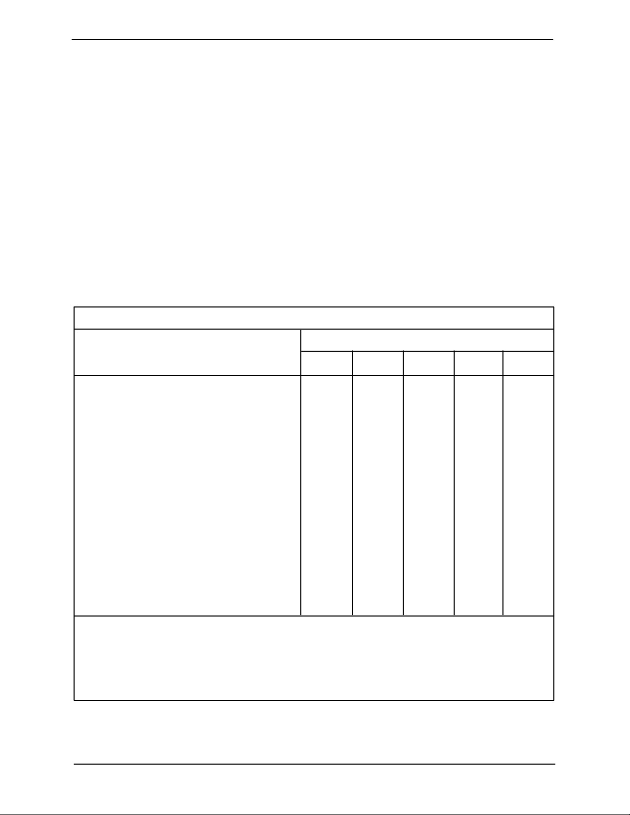
Preventive Maintenance Schedule
Service Interval*
Item
General Condition (Temperature, Unusual
Noises or Vibrations, Cracks, Leaks,
Loose Hardware, Etc.) I
Pump Performance (Gauges, Speed, Flow) I
Bearing Lubrication I R
Seal Lubrication (And Packing Adjustment,
If So Equipped) I R
V-Belts (If So Equipped) I
Air Release Valve Plunger Rod (If So Equipped) I C
Front Impeller Clearance (Wear Plate) I
Rear Impeller Clearance (Seal Plate) I
Check Valve I
Pressure Relief Valve (If So Equipped) C
Pump and Driver Alignment I
Shaft Deflection I
Bearings I
Bearing Housing I
Piping I
Driver Lubrication − See Mfgr’s Literature
Daily Weekly Monthly Semi-
Annually
Annually
Legend:
I = Inspect, Clean, Adjust, Repair or Replace as Necessary
C = Clean
R = Replace
* Service interval based on an intermittent duty cycle equal to approximately 4000 hours annually.
Adjust schedule as required for lower or higher duty cycles or extreme operating conditions.
TROUBLESHOOTING PAGE D − 3
Page 19
10 SERIES OM−04733
PUMP MAINTENANCE AND REPAIR - SECTION E
MAINTENANCE AND REPAIR OF THE WEARING PARTS OF THE PUMP WILL MAINTAIN PEAK
OPERATING PERFORMANCE.
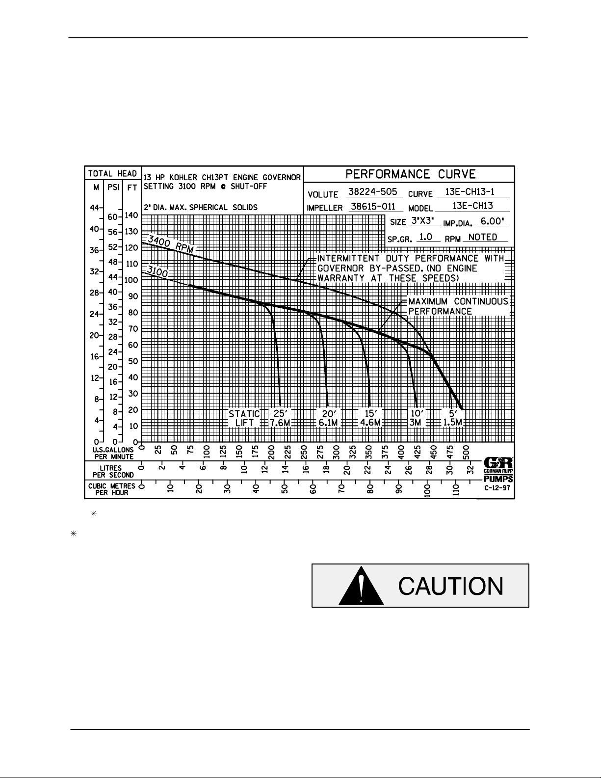
STANDARD PERFORMANCE FOR PUMP MODELS 13E52−CH13 And 13E52−CH13 S/G
Based on 70_ F (21_ C) clear water at sea level
with minimum suction lift. Since pump installations
are seldom identical, your performance may be different due to such factors as viscosity, specific
gravity, elevation, temperature, and impeller trim.
Contact the Gorman-Rupp Company to verify performance or part numbers.
Pump speed and operating condition
If your pump serial number is followed by an N",
your pump is NOT a standard production model.
MAINTENANCE & REPAIR PAGE E − 1
points must be within the continuous performance range shown on the curve.
Page 20
PARTS PAGE
10 SERIESOM−04733
SECTION DRAWING
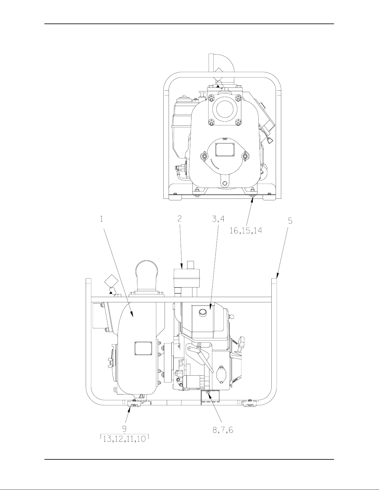
Figure 1. Pump Model 13E52−CH13
MAINTENANCE & REPAIRPAGE E − 2
Page 21
10 SERIES OM−04733
PARTS LIST
Pump Model 13E52−CH13
(From S/N 1341837 up)
If your pump serial number is followed by an N", your pump is NOT a standard production model. Contact
the Gorman-Rupp Company to verify part numbers.
ITEM
NO.
1 PUMP END ASSY 13E52−(CH13) −−− 1
2 MUFFLER KIT 48222−005 −−− 1
3 KOHLER CH13PT ENGINE 29127−091 −−− 1
4 FLAT WASHER K04 15991 2
5 ROLLOVER BASE 41583−334 24150 1
6 HEX HD CAPSCREW B0604 15991 2
7 FLAT WASHER K06 15991 2
8 LOCKWASHER J06 15991 2
9 RUBBER FOOT MOUNTING KIT 48152−603 −−− 1
10 −RUBBER BUMPER S1224 −−− 4
11 −HEX HD CAPSCREW B0504 15991 4
12 −FLAT WASHER K05 15991 4
13 −HEX NUT W/FLANGE 21765−312 −−− 4
14 HEX HD CAPSCREW B0706 15991 2
15 FLAT WASHER K07 15991 2
16 HEX NUT WITH FLANGE 21765−315 −−− 2
NOT SHOWN:
PART NAME
INSTRUCTION TAG 38817−085 −−− 1
G-R DECAL GR−03 −−− 1
INSTRUCTION LABEL 2613DK −−− 1
WARNING DECAL 2613FE −−− 1
ENGINE START UP TAG 38816−269 −−− 1
PRIMMING STICKER 6588AH −−− 1
STRAINER 4917 24001 1
PART
NUMBER
MAT’L
CODE
QTY
INDICATES PARTS RECOMMENDED FOR STOCK
MAINTENANCE & REPAIR PAGE E − 3
Page 22
SECTION DRAWING
10 SERIESOM−04733
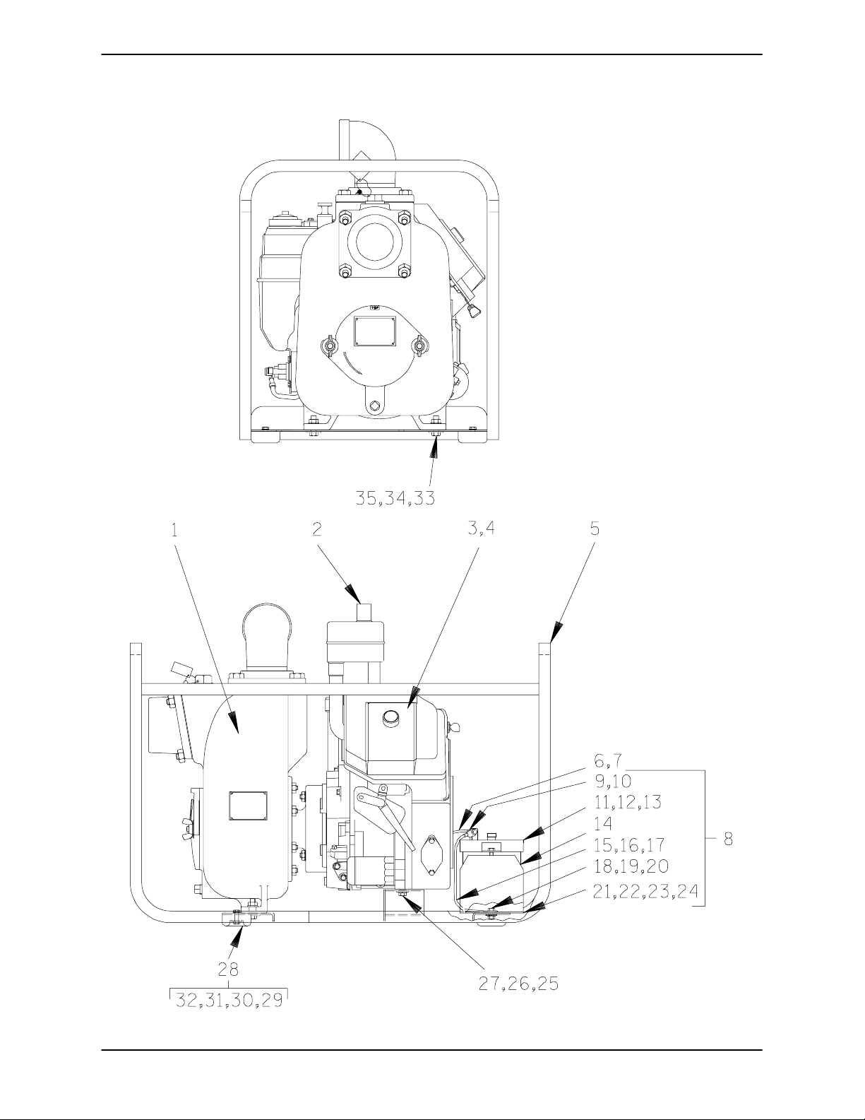
Figure 2. Pump Model 13E52−CH13 S/G
MAINTENANCE & REPAIRPAGE E − 4
Page 23
10 SERIES OM−04733
PARTS LIST
Pump Model 13E52−CH13 S/G
ITEM
NO.
1 PUMP END ASSY 13E52-(CH13) −−− 1
2 MUFFLER KIT 48222−005 −−− 1
3 KOHLER CH13 ENGINE 29127-092 −−− 1
4 FLAT WASHER K04 15991 2
5 ROLL-OVER BASE 41583−334 24150 1
6 #4 START CABLE 47311−506 −−− 1
7 FLAT WASHER K04 15991 2
8 BATTERY BOX ASSY GRP40−05 −−− 1
9 −HEX HD CAPSCREW B0503 15991 1
10 −FLANGED HEX NUT 21765−312 −−− 1
11 −BATTERY BOX COVER 11870 24000 1
12 −HEX HD CAPSCREW B0504 15991 1
13 −FLANGED HEX NUT 21765−312 −−− 1
14 −BATTERY SEE OPTIONS −−− 1
15 −#4 START CABL SUB 47311−542 −−− 1
16 −HEX HD CAPSCREW B0503 15991 1
17 −FLANGED HEX NUT 21765−312 −−− 1
18 −HEX HD CAPSCREW B0503 15991 1
19 −FLANGED HEX NUT 21765−312 −−− 1
20 −T TYPE LOCKWASHER BL05 15991 2
21 −BATTERY BOX 34383−017 15120 1
22 −HEX HD CAPSCREW B0503 15991 1
23 −FLANGED HEX NUT 21765−312 −−− 1
24 BATTERY TAG 38818−680 −−− 1
25 HEX HD CAPSCREW B0604 15991 2
26 FLAT WASHER K06 15991 2
27 LOCKWASHER J06 15991 2
28 RUBBER FOOT MOUNTING KIT 48152−603 −−− 1
29 −RUBBER BUMPER S1224 −−− 4
30 −HEX HD CAPSCREW B0504 15991 4
31 −FLAT WASHER K05 15991 1
32 −FLANGED HEX NUT 21765−312 −−− 1
33 HEX HD CAPSCREW B0706 15991 1
34 −FLAT WASHER K07 15991 1
35 HEX NUT WITH FLANGE 21765-315 −−− 2
NOT SHOWN:
OPTIONAL:
PART NAME
WARNING DECAL 2613FE −−− 1
HAND CARRY DECAL 2613FT −−− 4
INSTRUCTION TAG 38817−085 −−− 1
G−R DECAL GR−03 −−− 1
ENGINE START UP TAG 38816−269 −−− 1
PRIMMING STICKER 6588AH −−− 1
STRAINER 4917 24000 1
BATTERY S1680 −−− 1
PART
NUMBER
MAT’L
CODE
QTY
INDICATES PARTS RECOMMENDED FOR STOCK
MAINTENANCE & REPAIR PAGE E − 5
Page 24
SECTION DRAWING
10 SERIESOM−04733
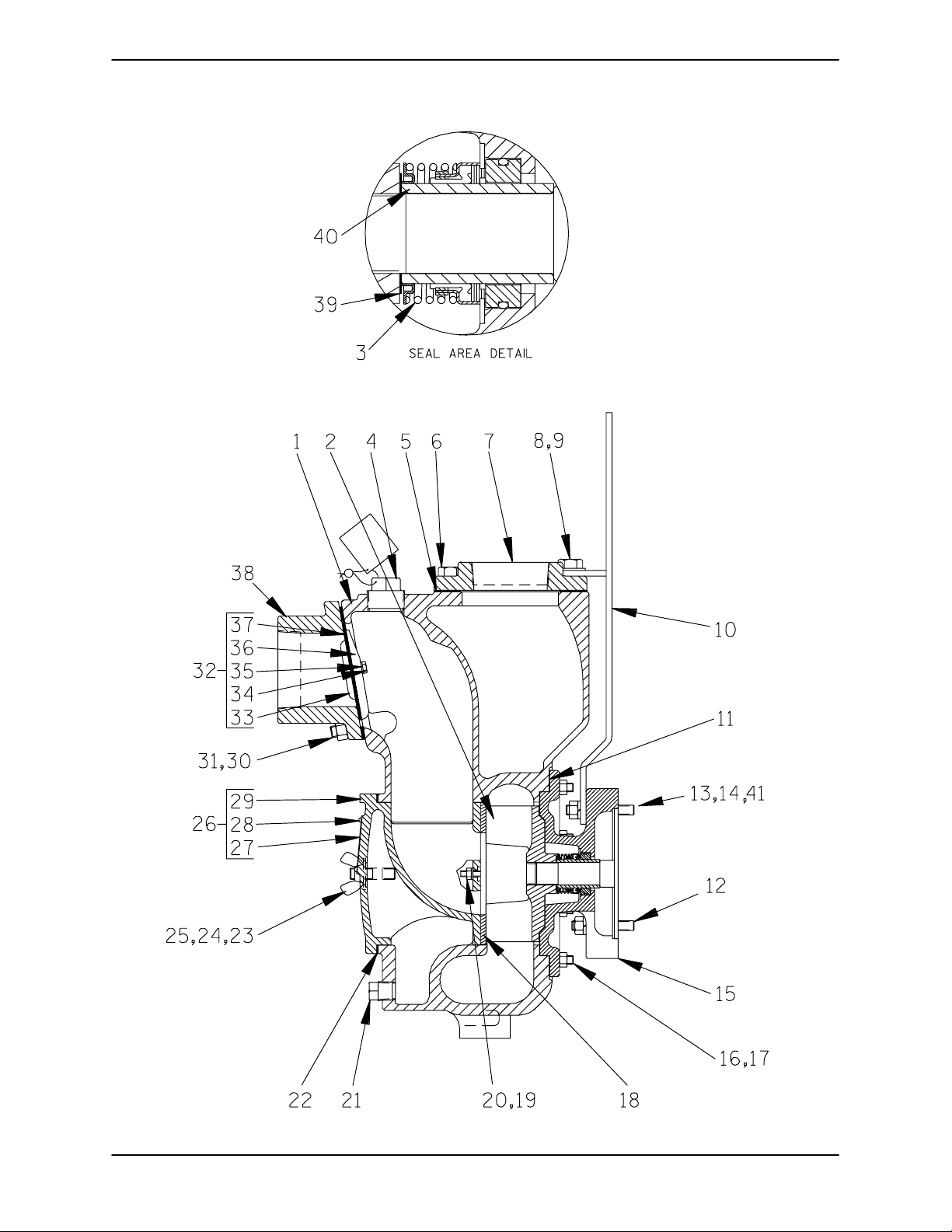
Figure 3. Pump End Assembly 13E52−(CH13)
MAINTENANCE & REPAIRPAGE E − 6
Page 25
10 SERIES OM−04733
PARTS LIST
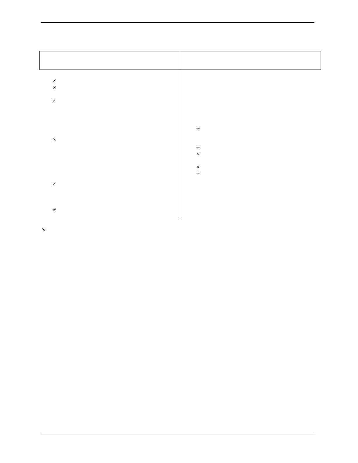
Pump End Assembly 13E52−(CH13)
ITEM
PART NAME PART
NO.
NUMBER
MAT’L
CODE
QTY ITEM
NO.
PART NAME PART
NUMBER
MAT’L
CODE
QTY
1 PUMP CASING 38224−505 10010 1
2 IMPELLER 38615−011 10010 1
SEAL ASSY 25284−951 −−− 1
3
4 FILL PLUG ASSY 48271−065 −−− 1
5 DISCH FLANGE GSKT 38687−009 20000 1
6 HEX HD CAPSCREW B1005 15991 2
7 DISCHARGE FLANGE 38644−202 10010 1
8 HEX HD CAPSCREW B1007 15991 2
9 FLAT WASHER 21161−442 −−− 2
10 HOISTING BAIL ASSY 44711−021 24150 1
11 CASING GSKT SET 48211−022 −−− 1
12 STUD C0610 15991 2
13 FLAT WASHER K06 15991 2
14 HEX NUT WITH FLANGE 21765−314 −−− 4
15 INTERMEDIATE 38264−323 10010 1
16 STUD C0606 15991 8
17 HEX NUT D06 15991 8
18 WEAR PLATE ASSY 46451−302 24150 1
19 LOCKWASHER J04 15991 2
20 HEX NUT D04 15991 2
21 CASING DRAIN PLUG P08 15079 1
22 COVER PLATE GSKT 38682−015 20000 1
23 STUD C0808 15991 2
INDICATES PARTS RECOMMENDED FOR STOCK
24 FLAT WASHER K08 15991 2
25 COVER WING NUT BB08 15991 2
26 COVER PLATE ASSY 42111−997 −−− 1
27 −WARNING PLATE 2613EV 13990 1
28 −DRIVE SCREW BM#04−03 17000 4
29 −BACK COVER PLATE NOT AVAILABLE 1
30 STUD C0808 15991 4
31 HEX NUT D08 15991 4
32 CHECK VALVE ASSY 46413−029 −−− 1
33 −VALVE WEIGHT 19 10010 1
34 −HEX HD CAPSCREW B0403−1/2 17000 2
35 −LOCKWASHER J04 17000 2
36 −VALVE WEIGHT 4718 10010 1
37 −CHECK VALVE GSKT 38671−626 19070 1
38 SUCTION FLANGE 38645−201 10010 1
39 IMP ADJ SHIM SET 2X 17090 REF
40 SHAFT SLEEVE 2146M 16000 1
41 STUD C0611 15991 2
NOT SHOWN:
NAME PLATE 38818−021 13990 1
DRIVE SCREW BM#04−03 17000 4
STRAINER 2690 24000 1
SUCTION STICKER 6588AG −−− 1
DISCHARGE STICKER 6588BJ −−− 1
MAINTENANCE & REPAIR PAGE E − 7
Page 26
10 SERIESOM−04733
PUMP AND SEAL DISASSEMBLY
AND REASSEMBLY
Review all SAFETY information in Section A.
Follow the instructions on all tags, label and decals attached to the pump.
This pump requires little service due to its rugged,
minimum-maintenance design. However, if it becomes necessary to inspect or replace the wearing
parts, follow these instructions which are keyed to
the sectional views (see Figures 1, 2 and 3) and the
accompanying parts lists.
This manual will alert personnel to known procedures which require special attention, to those
which could damage equipment, and to those
which could be dangerous to personnel. However,
this manual cannot possibly anticipate and provide
detailed precautions for every situation that might
occur during maintenance of the unit. Therefore, it
is the responsibility of the owner/maintenance personnel to ensure that only safe, established main-
tenance procedures are used, and that any procedures not addressed in this manual are performed
only after establishing that neither personal safety
nor pump integrity are compromised by such practices.
Most service functions, such as impeller and seal
replacement, may be performed by draining the
pump and removing the pump casing. The following instructions assume complete disassembly is
required.
Before attempting to service the pump, shut down
the engine and disconnect the spark plug wire to
ensure that the pump will remain inoperative.
Close all valves in the suction and discharge lines.
3. Allow the pump to completely cool
if overheated.
4. Check the temperature before
opening any covers, plates, or
plugs.
5. Close the suction and discharge
valves.
6. Vent the pump slowly and cautiously.
7. Drain the pump.
Suction Check Valve Disassembly
(Figure 3)
Before attempting to service the pump, remove the
pump casing drain plug (21) and drain the pump.
Clean and reinstall the drain plug.
To service the suction check valve, remove the suction piping. Remove the nuts (31) securing the suction flange (38) to the pump casing (1). Pull the
check valve assembly (32) from the suction port.
Remove the hardware (34 and 35) securing the
check valve weights (33 and 36) to the check valve
gasket (37).
If no further disassembly is required, see Suction
Check Valve Installation.
Back Cover Removal
(Figure 3)
The wear plate assembly (18) can be serviced after
the back cover assembly (26) has been removed.
Remove the wing nuts and flat washers (24 and 25)
securing the back cover to the casing. Pull the
back cover and assembled wear plate from the
pump casing. Inspect the wear plate and if replacement is required, remove the hardware (19 and 20)
securing it to the back cover.
Before attempting to open or service the
pump:
1. Familiarize yourself with this manual.
2. Shut down the engine and disconnect the spark plug wire to ensure
that the pump will remain inoperative.
Remove the cover plate gasket (22) and clean the
mating surfaces.
Pump Casing Removal
(Figure 3)
To service the impeller or seal assembly, disconnect the discharge piping. See Figure 1 or 2 and re-
MAINTENANCE & REPAIRPAGE E − 8
Page 27
10 SERIES
OM−04733
move the hardware (8, 9, and 10) securing the
pump casing (1) to the base (4).
Disengage the hardware (8 and 9) securing the
pump casing (1) to the hoisting bail (10). Support
the pump casing using a suitable hoist and sling,
and remove the nuts (17) securing the pump casing to the intermediate (15). Separate the parts by
pulling the casing straight away from the intermediate. Tie and tag any shims used under the
mounting feet to level the pump casing.
Remove the casing gasket set (11). Record the
thickness of the gaskets for future reference. Clean
the mating surfaces of the intermediate and pump
casing.
Impeller Removal
(Figure 3)
To loosen the impeller (2), tap the vanes of the impeller in a counterclockwise direction (when facing
the impeller) with a block of wood or a soft-faced
mallet. Unscrew the impeller and replace it if
cracked or badly worn. Use caution when removing the impeller; tension on the seal spring will be
released as the impeller is unscrewed.
Slide the impeller adjusting shims (39) off the impeller shaft. Tie and tag the shims or measure and
record their thickness for ease of reassembly.
Seal Removal and Disassembly
(Figures 3 and 4)
stiff wires with hooked ends to pull the seal stationary seat out of the intermediate.
If no further disassembly is required, see Seal
Reassembly and Installation.
Seal Reassembly and Installation
(Figures 3 and 4)
Clean the seal cavity and shaft with a cloth soaked
in fresh cleaning solvent.
Most cleaning solvents are toxic and
flammable. Use them only in a well ventilated area free from excessive heat,
sparks, and flame. Read and follow all
precautions printed on solvent containers.
The seal is not normally reused because wear patterns on the finished faces cannot be realigned
during reassembly. This could result in premature
failure. If necessary to reuse an old seal in an emergency, carefully wash all metallic parts in fresh
cleaning solvent and allow to dry thoroughly.
Handle the seal parts with extreme care to prevent
damage. Be careful not to contaminate precision
finished faces; even fingerprints on the faces can
shorten seal life. If necessary, clean the faces with a
non-oil based solvent and a clean, lint-free tissue.
Wipe lightly in a circular pattern to avoid scratching the faces.
Remove the spring centering washer and seal
spring. Slide the shaft sleeve (40) and rotating portion of the seal off the shaft as an assembly. Lubricate the sleeve adjacent to the seal and work oil up
under the rubber bellows. Slide the rotating portion
of the seal off the shaft sleeve.
Remove the hardware (13 and 14) and carefully
slide the intermediate (15) and stationary portion of
the seal off the shaft as a unit. Use a suitably sized
dowel to press the stationary element out of the intermediate from the back side.
NOTE
The seal assembly may be removed without completely disassembling the pump by using a pair of
MAINTENANCE & REPAIR PAGE E − 9
Inspect the seal components for wear, scoring,
grooves, and other damage that might cause leakage. Clean and polish the shaft sleeve, or replace it
if there are nicks or cuts on either end. If any components are worn, replace the complete seal;
never mix old and new seal parts.
If a replacement seal is being used, remove it from
the container and inspect the precision finished
faces to ensure that they are free of any foreign
matter.
To ease installation of the seal, lubricate the Orings, sleeve and bellows with water or a very small
amount of oil, and apply a drop of light lubricating
oil on the finished faces. Assemble the seal as follows, (see Figure 4).
Page 28
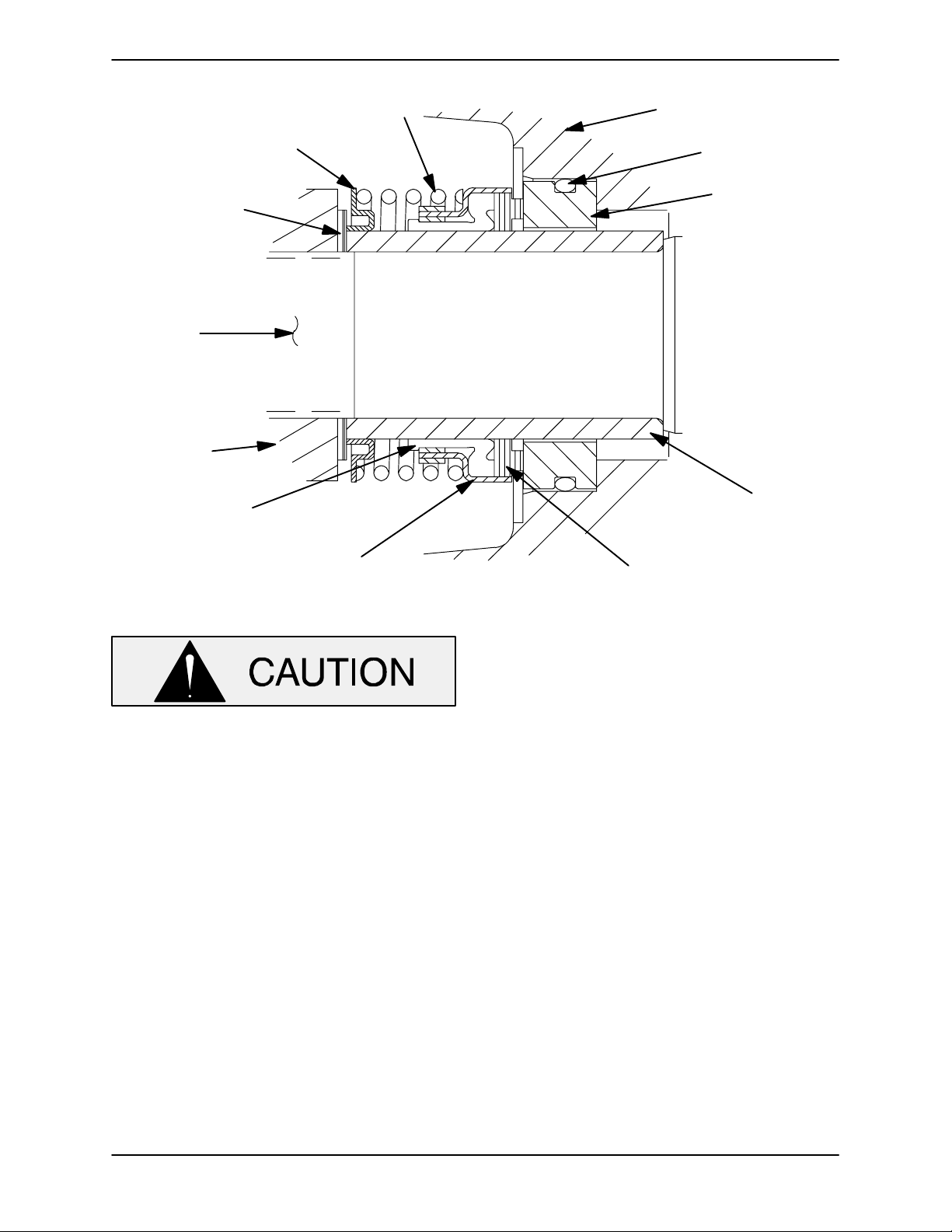
10 SERIESOM−04733
SPRING
CENTERING
WASHER
IMPELLER SHIMS
ENGINE
STUB
SHAFT
IMPELLER
BELLOWS
SPRING
INTERMEDIATE
O-RING
STATIONARY
SEAT AND SEAL
SHAFT
SLEEVE
RETAINER
Figure 4. 25284−951 Seal Assembly
This seal is not designed for operation at
temperatures above 160_F (71_C). Do not
use at higher operating temperatures.
Inspect the engine stub shaft for damage. Small
scratches or nicks may be removed with a fine file
or emery cloth. If the stub shaft is bent of excessively worn, replace the shaft (see the engine service
manual).
Position the intermediate against the engine bellhousing and secure it with hardware (13 and 14).
Assemble the O-ring into the stationary seat. Press
the stationary seat into the intermediate bore until
fully seated. A push tube cut from a length of plastic
pipe would aid this installation. The I.D. of the tube
should be approximately the same as the I.D. of the
seal spring.
Subassemble the rotating element into the retainer
and bellows. Apply a drop of light oil on the preci-
ROTATING ELEMENT
sion finished faces; never use grease. Use even
pressure to carefully press this subassembly onto
the sleeve (40) until the rotating element is just
flush with the chamfered end of the sleeve.
Slide the sleeve and assembled rotating portion of
the seal onto the shaft until the seal faces contact.
Continue to push the sleeve through the seal until it
seats squarely against the shaft shoulder.
Install the seal spring and spring centering washer.
Lubricate the seal as indicated in LUBRICATION,
after the impeller has been installed.
Impeller Installation And Adjustment
(Figure 3)
Inspect the impeller, and replace it if cracked or
badly worn. Install the same thickness of impeller
shims (39) as previously removed, and screw the
impeller onto the shaft until tight.
A clearance of .020 to .040 inch (0,51 to 1,02 mm)
between the impeller and the intermediate is necessary for maximum pump efficiency. Measure this
MAINTENANCE & REPAIRPAGE E − 10
Page 29
10 SERIES
OM−04733
clearance and add or remove impeller shims until
this clearance is reached.
Pump Casing Installation
(Figure 3)
Install the same thickness of pump casing gaskets
(11) as previously removed and secure the pump
casing to the intermediate with the nuts (17). Do
not fully tighten the nuts at this time.
A clearance of .008 to .015 inch (0,20 to 0,38 mm)
between the impeller and the wear plate is also recommended for maximum pump efficiency. Install
the back cover and set this clearance by adding or
removing gaskets in the pump casing gasket set
until the impeller binds against the wear plate when
the shaft is turned. After the impeller binds add
.015 inch (0,38 mm) of gaskets.
NOTE
An alternate method of adjusting this clearance is to
reach through the discharge port with a feeler
gauge and measure the gap. Add or subtract pump
casing gaskets accordingly.
After the face clearance has been set, tighten the
hardware securing the pump casing to the intermediate.
NOTE
Apply a film of ‘Never-Seez’ or equivalent compound on the back cover shoulder or any surface
which contacts the pump casing to ease future disassembly and to reduce rust and scale build up.
Replace the back cover gasket (22) and slide the
back cover assembly (26) into the pump casing.
Be sure the wear plate does not bind against the
pump casing.
Secure the back cover assembly with the hardware (24 and 25). Do not over tighten the wing
nuts; they should be just tight enough to ensure a
good seal at the back cover shoulder.
Suction Check Valve Installation
(Figure 3)
Inspect the check valve components and replace
as required. Subassemble the check valve weights
(33 and 36) and check valve gasket (37) with the
hardware (34 and 35).
Position the check valve assembly (32) in the suction port with the large weight (36) facing toward
the inside of the pump casing. Install the suction
flange (38) and secure with the nuts (31). Check
the operation of the check valve to ensure proper
seating and free movement.
Install the hardware (8 and 9) securing the pump
casing to the hoisting bail (10). See Figure 1 or 2
and secure the pump casing (1) to the base (4) with
the previously removed hardware (8, 9, and 10 ).
Be sure to reinstall any leveling shims used under
the mounting feet of the pump casing.
Back Cover Installation
(Figure 3)
Inspect the wear plate (18) and replace it if badly
worn or grooved. Install the wear plate on the back
cover using the hardware (19 and 20).
Clean any scale or debris from the back cover
shoulder and pump casing which might prevent a
good seal.
MAINTENANCE & REPAIR PAGE E − 11
Final Pump Assembly
(Figures 1 and 2)
Be sure the pump and engine are securely
mounted to the base.
Install the suction and discharge lines and open all
valves. Make certain that all piping connections are
tight, properly supported and secure.
Be sure the pump and engine have been properly
lubricated, see LUBRICATION.
Remove the fill plug assembly (4, Figure 3) and fill
the pump casing with clean liquid. Reinstall the fill
plug and tighten it.
Refer to OPERATION, Section C, before putting
the pump back into service.
Page 30

10 SERIESOM−04733
LUBRICATION
Seal Assembly
(Figure 2)
The seal assembly is lubricated by the medium being pumped and no additional lubrication is required.
Engine
Consult the literature supplied with the engine, or
contact your local Kohler engine representative.
MAINTENANCE & REPAIRPAGE E − 12
Page 31

For U.S. and International Warranty Information,
Please Visit www.grpumps.com/warranty
or call:
U.S.: 419−755−1280
International: +1−419−755−1352
For Canadian Warranty Information,
Please Visit www.grcanada.com/warranty
or call:
519−631−2870
THE GORMAN-RUPP COMPANY D MANSFIELD, OHIO
GORMAN-RUPP OF CANADA LIMITED D ST. THOMAS, ONTARIO, CANADA
 Loading...