

Gorman-Rupp Pumps 12B22-B User Manual
C
OM-00589-OB03
June 17, 1994
INSTALLATION, OPERATION,
AND MAINTENANCE MANUAL
WITH P ARTS LIST
10 SERIES PUMPS
MODEL
12B22---B
THE GORMAN-RUPP COMPANY D MANSFIELD, OHIO
GORMAN-RUPP OF CANADA LIMITED D ST. THOMAS, ONTARIO, CANADA Printed in U.S.A.
eCopyright by the Gorman-Rupp Company

TABLE OF CONTENTS
INTRODUCTION PAGE I --- 1.................................................
WARN ING S - SE CTI ON A PA GE A --- 1........................................
IN STA L LAT ION --- S E CT ION B PA GE B --- 1....................................
Pump Dimensions PAGE B --- 1.....................................................
PREINSTALLATION INSPECTION PAGE B --- 1............................................
POSITIONING PUMP PA GE B --- 2.......................................................
Lifting PA GE B --- 2.................................................................
Mounting PA GE B --- 2.............................................................
Clearance PA GE B --- 2.............................................................
SUCTION AND DISCHARGE PIPING PAGE B --- 2.........................................
Materials PA GE B --- 2..............................................................
Line Configuration PAGE B --- 2......................................................
Connections to Pump PAGE B --- 2..................................................
Gauges PA GE B --- 3...............................................................
SUCTION LINES PAGE B --- 3...........................................................
Fittings PA GE B --- 3...............................................................
Strainers PA GE B --- 3..............................................................
Sealing PAGE B --- 3...............................................................
Suction Lines In Sumps PAGE B --- 3.................................................
Suction Line Positioning PAGE B --- 3................................................
DISCHARGE LINES PA GE B --- 4........................................................
Siphoning PAGE B --- 4.............................................................
Valves PA GE B --- 4................................................................
Bypass Lines PAGE B --- 4..........................................................
AUTOMATIC AIR RELEASE VALVE PAGE B --- 5...........................................
Theory of Operation PAGE B --- 5....................................................
Air Release Valve Installation P AGE B -- - 6............................................
ALIGNMENT PAGE B --- 7..............................................................
Coupled Drives PA GE B --- 8........................................................
V --- Belt Drives PA GE B --- 8.........................................................
OPER AT IO N --- S ECT IO N C PAG E C --- 1......................................
PRIMING PA GE C --- 1.................................................................
STARTING PA GE C --- 1................................................................
Rotation PA GE C --- 1..............................................................
OPERATION PAGE C --- 2..............................................................
Lines W ith a Bypass PAGE C --- 2....................................................
Lines Without a Bypass PAGE C --- 2.................................................
Leakage PA GE C --- 2..............................................................
Liquid Temperature And Overheating PAGE C --- 2.....................................
Strainer Check PAGE C --- 2.........................................................
Pump Vacuum Check PAGE C --- 2..................................................
STOPPING PA GE C --- 3................................................................
Cold Weather Preservation PAGE C --- 3..............................................
BEARING TEMPERATURE CHECK PAGE C --- 3..........................................
TR OUB LES HOO TI NG --- SE C TIO N D PA GE D --- 1..............................
i

TABLE OF CONTENTS
(continued)
PUMP MAINTENANCE AND REPAIR - SECTION E PAGE E --- 1.................
STANDARD PERFORMANCE CURVE PAGE E --- 1........................................
PARTS LIST:
Pump Model PA GE E --- 3..........................................................
PUMP AND SEAL DISASSEMBLY AND REASSEMBLY PAGE E --- 4.........................
Suction Check Valve Removal and Disassembly PAGE E --- 4...........................
Back Cover Removal PA GE E --- 4...................................................
Pump Casing Removal PAGE E --- 4.................................................
Impeller Removal P AGE E -- - 5......................................................
Seal Removal and Disassembly PAGE E --- 5..........................................
Shaft and Bearing Removal and Disassembly PAGE E --- 5.............................
Shaft and Bearing Reassembly and Installation PAGE E --- 6............................
Seal Reassembly and Installation PAGE E - -- 7........................................
Impeller Installation And Adjustment P AGE E -- - 9......................................
Pump Casing Installation PAGE E --- 9................................................
Back Cover Installation PAGE E --- 9.................................................
Suction Check Valve Installation P AGE E --- 9.........................................
Final Pump Assembly PAGE E --- 10..................................................
LUBRICATION PA GE E --- 10.............................................................
Seal Assembly PAGE E --- 10.........................................................
Bearings PAGE E --- 10..............................................................
Power Sou rce PA GE E --- 10.........................................................
ii
10 SERIES
OM--00589--03
INTRODUCTION
This Installation, Operation, and Maintenance
manual is designed to help you achieve the best
performance and longest life from your GormanRupp pump.
This pump is a 10 Series, semi-open impeller,selfpriming centrifugal model with a suction check
valve.Thepumpisdesignedforhandlingcorrosive
liquids containing specified entrained solids, residues and slurries. The basic material of construc-
The Gorman-Rupp Company or Gorman-Rupp of Canada Limited
P.O. Box 1217 70 Burwell Road
Mansfield, Ohio 44901-1217 St. Thomas, Ontario N5P 3R7
The following are used t o alert maintenance personnel to procedures which require special attention, to
those which could damage equipment, and to those which could be dangerous to personnel:
tion for wetted parts is type 316 stainless steel.
Forinformation ortechnicalassistance onthe pow-
er source, contact the power source manufacturer’s local dealer or representative.
If there are any questions regarding the pump or
its application which are not covered in this manual or in other literature accompanying this unit,
please contact your Gorman-Rupp distributor, or
write:
Immediate hazards whichWILL result in
severe personal injury or death. These
instructions describe the procedure required and the injury which will result
from failure to follow the procedure.
Hazards or unsafe practices which
COULDresult in severe personal injury
or death. These instructions describe
the procedure required and the injury
which could result from failure to follow
the procedure.
HazardsorunsafepracticeswhichCOULD
result in minor personal injury or product
or property damage. These instructions
describe the requirements and the possible damagewhich could result fromfailure
to follow the procedure.
NOTE
Instructions to aid in installation, operation, and
maintenance or which clarify a procedure.
PAGE I -- 1INTRODUCTION
10 SERIES
SAFETY - SECTION A
Thisinformationappliesto10Seriesba sic pumps. Gorman-Rupp has no control over or particular knowledge of the
power source which will be used. Refer
to the manual accompanying the power
sourcebefore attempting to beginoperation.
OM--00589--03
Afterthe pump hasbeen installed,make
certain that the pump and all piping or
hose connections are tight, properly
supportedand securebeforeoperation.
Beforeattempting toopenorservic e the
pump:
1. Familiarize yourself with this manual.
2. Disconnect or lock out the power
sourcetoensurethatthe pumpwill
remain inoperative.
3. Allowthe pump to completelycool
if overheated.
4. Check the temperature before
opening any covers, plates, or
plugs.
5. Close the suction and discharge
valves.
6. Vent the pump slowly and cautiously.
7. Drain the pump.
Do not operate the pump against a
closeddischarge valve forlongperiods
oftime.Ifoperatedagainstacloseddischarge valve, pump components will
deteriorate, and the liquid could come
to a boil, build pressure, and cause the
pump casing to rupture or explode.
Do not remove plates, covers, gauges,
pipe plugs, or fittings from an overheated pump. Vaporpressure within the
pump can cause parts being disen gagedto be ejected withgreatforce.Allow the pump to cool before servicing.
This pump is designed to handle corrosive liquids containing specified entrained solids,residuesand slurries. Do
not attempt to pump volatile or flammable liquids which may damage the
pumpor endanger personnel asaresult
of pump failure.
This pump is designed to pump materials which could cause serious illness or
injury through direct exposure or
emitted fumes. Wear protective clothing, such as rubber gloves, face mask,
and rubber apron, as necessary before
disassembling the pump or piping.
PAGE A -- 1SAFETY
10 SERIESOM--00589--03
Overheating may produce dangerous
fumes. Use extreme caution when ventingthepump, orwhenremovingcovers,
plates,plugs,orfittings.
Do not operate the pump without
shields and/or guards in plac e over the
drive shafts, belts, and/or couplings, or
other rotating parts. Exposed rotating
parts c an catch clothing, fingers, or
tools, causing severe injury to personnel.
Neverrunthispumpbackwards.Be certain that rotation is correct before fully
engaging the pump.
PAGE A -- 2
SAFETY
10 SERIES OM--00589--03
INSTALLATION --- SECTION B
Review all SAFETY information in Section A.
Since pump installations areseldom identical,this
section offers only general recommendations and
practices required to inspect, position, and arrange the pump and piping.
Most of the information pertains to a standard
staticliftapplicationwherethe pump ispositioned
above the free level of liquid to be pumped.
If installed in a flooded suction application where
the liquidis supplied to the pump under pressure,
some of the information such as mounting, line
configuration, and priming must be tailored to the
OUTLINE DRAWING
specific application. Since the pressure supplied
to the pump is critical to performance and safety,
besuretolimittheincomingpressureto50%ofthe
maximum permissible operating pressure as
shown on the pump performance curve (see Section E, Page 1).
Forfurther assistance,contact yourGorman-Rupp
distributor or t he Gorman-Rupp Company.
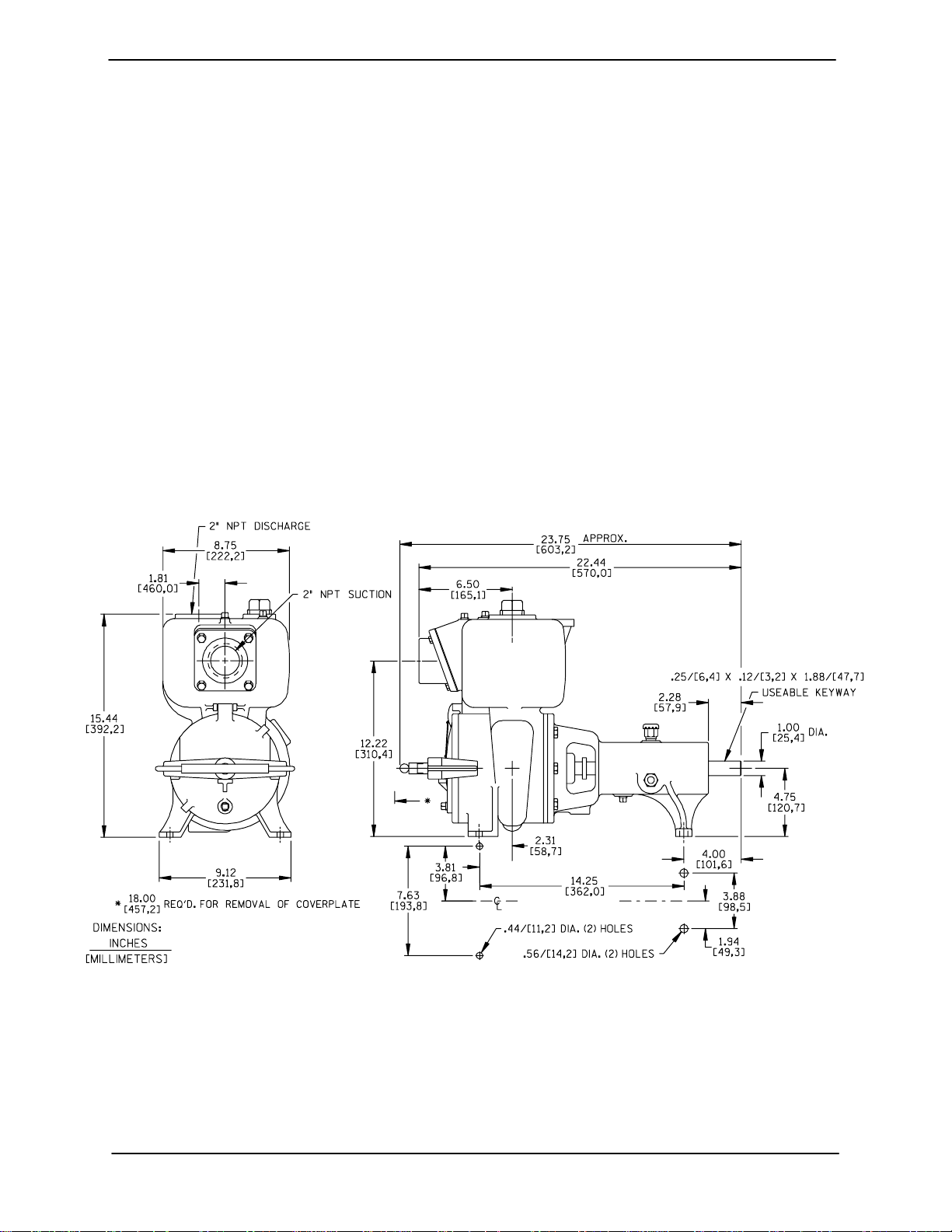
Pump Dimensions
SeeFigureB---1fortheapproximatephysicaldimensions of this pump.
Figure B--1. Pump Model 12B22--B
PREINSTALLATION INSPECTION
Thepump assembly wasinspected and tested before shipment from the factory. Before installation,
inspect the pump fordamage which may have occurred during shipment. Check a s follows:
a. Inspect the pump forcracks,dents, damaged
threads, and other obvious damage.
b. Check for and tighten loose attaching hard-
ware. Since gaskets tend to shrink after drying, check for loose hardware at mating surfaces.
PAGE B -- 1INSTALLATION
OM--00589--03 10 SERIES
c. Carefully read all tags, decals, and markings
onthepump assembly,and perform allduties
indicated. Note that the pump shaft rotates in
the required direction.
Only operate this pump in the direction indicated by the arrow on the pump body
and on the accompanying decal. Otherwise, the impeller could become loosened
from the shaft and seriously damage the
pump.
d. Check levels and lubricate as necessary. Re-
fer to LUBRICATION in the MAINTENANCE
AND REPAIR section of this manual and perform duties as instructed.
e. If the pump has been stored for more than 12
months, some of the components or lubricants may have exceeded their maximum
shelf life. These must be inspected or re-
placed to ensure maximum pump service.
damaged ifthe chains or cables usedtolift
andmovetheunitareimproperlywrapped
around the pump.
Mounting
Locatethepumpinanaccessibleplaceascloseas
practicalto the liquid being pumped. Levelmounting is essential for proper operation.
The pump may have to be supported or shimmed
to provide for level operation or to eliminate vibration.
Clearance
A minimum clearance of 18 inches in front of the
coverplate isrequiredto permitremovalofthe cover and easy access to the pump interior.
SUCTION AND DISCHARGE PIPING
Pump performance is adversely effected by increased suction lift, discharge elevation, and friction losses. See the performance curve on Page
E-1to besureyour overallapplication allowspump
to operate within the safe operation range.
If the maximum shelf life has been exceeded, or if
anything appears to be abnormal, contact your
Gorman-Rupp distributor or the factory to determine the repair or updating policy. Do not put the
pump into service until appropriate action has
been taken.
POSITIONING PUMP
Lifting
Useliftingequipmentwith a capacity ofatleast650
pounds (295 kg). This pump weighs approxi-
mately 125 pounds (57 kg), not including the
weight of accessories, base a nd power source.
Customerinstalledequipmentsuchassuctionand
discharge piping must be removed before attempting to lift.
Thepumpassemblycanbeseriously
Materials
Either pipe or hose maybe used for suction and
discharge lines; however, the materials must be
compatiblewith theliquidbeingpumped.If hoseis
used in suction lines, it must be the rigid-wall, reinforced type to prevent collapse under suction. Using piping couplings in suction lines is not recommended.
Line Configuration
Keep suction and discharge lines as straight as
possible to minimize friction losses. Make minimum use of elbows and fittings, w hich substantiallyincrease frictionloss.Ifelbowsarenecessary,
use the long-radius type to minimize friction loss.
Connections to Pump
Before tightening a connecting flange, align it exactlywith the pump port. Never pulla pipe lineinto
place by tightening the flange bolts and/or couplings.
PAGE B -- 2 INSTALLATION

10 SERIES OM--00589--03
Lines near the pump must be independently supported to avoid strain on the pump which could
cause excessive vibration, decreased bearing life,
and increased shaft and seal wear. If hose-type
linesareused, theyshouldhaveadequatesupport
to secure them when filled with liquid and under
pressure.
Gauges
Most pumps are drilled and tapped for installing
dischargepressureandvacuumsuctiongauges. If
these gauges are desired for pumps that are not
tapped, drill a nd tap the suction and discharge
lines not less than 18 inches (457,2 mm) from the
suction and discharge ports and install the lines.
Installationcloserto the pump may result in erratic
readings.
SUCTION LINES
To avoid airpockets whichcouldaffect pumppriming, the suction line must be as short and direct as
possible.When operationinvolvesasuctionlift,the
line must always slope upward to the pump from
the source of the liquid being pumped; if the line
slopes down to the pump at any point along the
suction run, air pockets will be created.
Fittings
three or four times the cross section of the suction
line,and that the openings will not permit passage
of solids larger than the solids handling capability
of the pump.
This pump is designed to handle up to 1-1/4 inch
(31,8 mm) diameter spherical solids.
Sealing
Since even a slight leak will affect priming, head,
and capacity, especially when operating with a
high suction lift, all connections in the suction line
should be sealed with pipe dope to ensure an airtight seal. Follow the sealant manufacturer’s recommendations when selecting and applying the
pipe dope. The pipe dope should be compatible
with the liquid being pumped.
Suction Lines In Sumps
If a single suction line is installed in a sump, it
should be positioned away from the wall of the
sumpat a distance equal to1-1/2 times thediameter of the suction line.
If there is a liquid flow from an open pipe into the
sump, the flow should be kept away from the suctioninlet because the inflowwill carry air down into
the sump, and air entering the suction line w ill reduce pump efficiency.
Suction lines shouldbe the same size as the pump
inlet. If reducers are used in suction lines, they
should be the eccentric type, and should be installedwith the flat part ofthe reducers uppermost
to avoid creating air pockets. Valves are not normally used in suction lines, but if a valve is used,
install it with the stem horizontal to avoid air pockets.
Strainers
If a strainer is furnished with the pump, be certain
touseit; any sphericalsolidswhichpass througha
strainer furnished with the pump will also pass
through the pump itself.
If a strainer is not furnished with the pump, but is
installed by the pump user, make certain that the
total area of the openings in the strainer is at least
Ifit is necessary to position inflowclose to the suctioninlet,installa bafflebetween theinflowand the
suctioninlet at a distance 1-1/2times the diameter
of the suction pipe. The baffle will allow entrained
air to escape from the liquid before it is drawn into
the suction inlet.
If two suction lines are installed in a single sump,
theflowpaths mayinteract, reducing theefficiency
of one or both pumps. To avoid this, position the
suction inlets s o that they are separated by a distance equal to at least 3 times the diameter of the
suction pipe.
Suction Line Positioning
The depth of submergence of the suction line is
critical to efficient pump operation. Figure B---2
shows recommended minimum submergence vs.
velocity .
PAGE B -- 3INSTALLATION

OM--00589--03 10 SERIES
NOTE
The pipe submergence required may be reduced
by installinga standardpipe increaser fitting at the
endof thesuction line. The largeropening size will
reduce the inlet velocity. Calculate the required
submergence using the following formula based
on the increased opening size (area or diameter).
Figure B--2. Recommended Minimum Suction Line Submergence vs. Velocity
DISCHARGE LINES
Siphoning
Donot terminate the discharge lineat a level lower
than that of the liquid being pumped unless a siphon breaker is used in the line. Otherwise, a siphoning action causing damage to the pump
could result.
Valves
If a throttling valve is desired in the discharge line,
useavalveaslargeasthelargestpipetominimize
friction losses. Never install a throttling valve in a
suction line.
A check valvein the discharge lineis normally recommended, but it is not necessary in low discharge head applications.
Withhighdischargeheads,itisrecommendedthat
a throttling valve and a system check valve be installed in the discharge line to protect the pump
from excessive shock pressure and reverse rotation when it is stopped.
Iftheapplicationinvolvesa highdischarge
head, gradually close the discharge
throttling valve before stopping the pump.
Bypass Lines
Self-primingpumps are not air compressors. Duringtheprimingcycle, air from the suction line must
be vented to atmosphere on the discharge side. If
the discharge line is open, this air will be vented
through the discharge. However, if a check valve
has been installed in the discharge line, the dischargesideofthepumpmustbeopenedtoatmosphericpressurethrough abypass line installedbe-
PAGE B -- 4 INSTALLATION
 Loading...