

Page 1
ACEU
OM-06592-01
September 17, 2012
INSTALLATION, OPERATION,
AND MAINTENANCE MANUAL
WITH PARTS LIST
10 SERIES PUMP
MODEL
112D60-B-TCD914L6
THE GORMAN‐RUPP COMPANY D MANSFIELD, OHIO
www.grpumps.com
GORMAN‐RUPP OF CANADA LIMITED D ST. THOMAS, ONTARIO, CANADA Printed in U.S.A.
e2012 The Gorman‐Rupp Company
Page 2

Register your new
Gorman‐Rupp pump online at
www.grpumps.com
Valid serial number and e‐mail address required.
The engine exhaust from this
product contains chemicals
known to the State of California to
cause cancer, birth defects or
other reproductive harm.
RECORD YOUR PUMP MODEL AND SERIAL NUMBER
Please record your pump model and serial number in the
spaces provided below. Your Gorman‐Rupp distributor
needs this information when you require parts or service.
Pump Model:
Serial Number:
Page 3

TABLE OF CONTENTS
INTRODUCTION PAGE I - 1.................................................
WARNINGS ‐ SECTION A PAGE A - 1........................................
INSTALLATION - SECTION B PAGE B - 1....................................
Pump Dimensions PAGE B - 1.....................................................
PREINSTALLATION INSPECTION PAGE B - 1............................................
POSITIONING PUMP PAGE B - 2.......................................................
Lifting PAGE B - 2.................................................................
Mounting PAGE B - 2.............................................................
Clearance PAGE B - 2.............................................................
SUCTION AND DISCHARGE PIPING PAGE B - 2.........................................
Materials PAGE B - 2..............................................................
Line Configuration PAGE B - 2......................................................
Connections to Pump PAGE B - 2..................................................
Gauges PAGE B - 2...............................................................
SUCTION LINES PAGE B - 3...........................................................
Fittings PAGE B - 3...............................................................
Strainers PAGE B - 3..............................................................
Sealing PAGE B - 3...............................................................
Suction Lines In Sumps PAGE B - 3.................................................
Suction Line Positioning PAGE B - 3................................................
DISCHARGE LINES PAGE B - 4........................................................
Siphoning PAGE B - 4.............................................................
Valves PAGE B - 4................................................................
Bypass Lines PAGE B - 4..........................................................
AUTOMATIC AIR RELEASE VALVE PAGE B - 6...........................................
Theory of Operation PAGE B - 6....................................................
Air Release Valve Installation PAGE B - 6............................................
ALIGNMENT PAGE B - 7..............................................................
OPERATION - SECTION C PAGE C - 1......................................
PRIMING PAGE C - 1.................................................................
STARTING PAGE C - 1................................................................
Rotation PAGE C - 1..............................................................
OPERATION PAGE C - 2..............................................................
Lines With a Bypass PAGE C - 2....................................................
Lines Without a Bypass PAGE C - 2.................................................
Leakage PAGE C - 2..............................................................
Liquid Temperature And Overheating PAGE C - 2.....................................
Strainer Check PAGE C - 2.........................................................
Pump Vacuum Check PAGE C - 3..................................................
STOPPING PAGE C - 3................................................................
Cold Weather Preservation PAGE C - 3..............................................
BEARING TEMPERATURE CHECK PAGE C - 3..........................................
TROUBLESHOOTING - SECTION D PAGE D - 1..............................
i
Page 4

TABLE OF CONTENTS
(continued)
PUMP MAINTENANCE AND REPAIR ‐ SECTION E PAGE E - 1.................
STANDARD PERFORMANCE CURVE PAGE E - 1........................................
PARTS LIST:
Pump Model PAGE E - 3..........................................................
Pump End Assembly PAGE E - 5...................................................
PUMP AND SEAL DISASSEMBLY AND REASSEMBLY PAGE E - 6.........................
Suction Check Valve Disassembly PAGE E - 6........................................
Wear Plate And Suction Head Removal PAGE E - 6...................................
Impeller Removal PAGE E - 7......................................................
Seal Removal and Disassembly PAGE E - 7..........................................
Pump Disassembly PAGE E - 7.....................................................
Shaft and Bearing Removal and Disassembly PAGE E - 8.............................
Shaft and Bearing Reassembly and Installation PAGE E - 9............................
Impeller Back Clearance PAGE E - 10................................................
Seal Reassembly and Installation PAGE E - 11........................................
Impeller Installation And Adjustment PAGE E - 12......................................
Pump Casing Installation PAGE E - 13................................................
Wear Plate And Suction Head Installation PAGE E - 13.................................
Suction Check Valve Assembly PAGE E - 13..........................................
Final Pump Assembly PAGE E - 14..................................................
LUBRICATION PAGE E - 14.............................................................
Bearings PAGE E - 14..............................................................
Seal Assembly PAGE E - 14.........................................................
Engine PAGE E - 14................................................................
ii
Page 5
10 SERIES
OM-06592
INTRODUCTION
Thank You for purchasing a Gorman‐Rupp pump.
Read this manual carefully to learn how to safely
install and operate your pump. Failure to do so
could result in personal injury or damage to the
pump.
This pump is a 10 Series, semi‐open impeller, self‐
priming centrifugal model with a suction check
valve. The pump is flex‐coupled to a Deutz diesel
engine. It is designed for handling most non‐vola
tile, non‐corrosive liquids containing specified en
trained solids. The basic material of construction
for wetted parts is gray iron, with an alloy steel im
peller shaft.
Because pump installations are seldom identical,
this manual cannot possibly provide detailed in
structions and precautions for every aspect of
each specific application. Therefore, it is the re
sponsibility of the owner/installer of the pump to
ensure that applications not addressed in this
manual are performed only after establishing that
neither operator safety nor pump integrity are com
promised by the installation. Pumps and related
equipment must be installed and operated ac
cording to all national, local and industry stan
dards.
If there are any questions regarding the pump or
its application which are not covered in this man
ual or in other literature accompanying this unit,
please contact your Gorman‐Rupp distributor, or
The Gorman‐Rupp Company:
The Gorman‐Rupp Company
P.O. Box 1217
Mansfield, Ohio 44901-1217
Phone: (419) 755-1011
or:
Gorman‐Rupp of Canada Limited
70 Burwell Road
St. Thomas, Ontario N5P 3R7
Phone: (519) 631-2870
For information or technical assistance on the en
gine, contact the engine manufacturer's local
dealer or representative.
The following are used to alert maintenance per
sonnel to procedures which require special atten
tion, to those which could damage equipment, and
to those which could be dangerous to personnel:
Immediate hazards which WILL result in
severe personal injury or death. These
instructions describe the procedure re
quired and the injury which will result
from failure to follow the procedure.
Hazards or unsafe practices which
COULD result in severe personal injury
or death. These instructions describe
the procedure required and the injury
which could result from failure to follow
the procedure.
Hazards or unsafe practices which COULD
result in minor personal injury or product
or property damage. These instructions
describe the requirements and the possi
ble damage which could result from failure
to follow the procedure.
NOTE
Instructions to aid in installation, operation,and
maintenance, or which clarify a procedure.
PAGE I - 1INTRODUCTION
Page 6
10 SERIES OM-06592
SAFETY - SECTION A
This information applies to 10 Series en
gine driven pumps. Refer to the manual
accompanying the engine before at
tempting to begin operation.
Because pump installations are seldom
identical, this manual cannot possibly
provide detailed instructions and pre
cautions for each specific application.
Therefore, it is the owner/installer's re
sponsibility to ensure that applications
not addressed in this manual are per
formed only after establishing that nei
ther operator safety nor pump integrity
are compromised by the installation.
Before attempting to open or service the
pump:
1. Familiarize yourself with this man
ual.
2. Switch off the engine ignition and
remove the key to ensure that the
pump will remain inoperative.
3. Allow the pump to completely cool
if overheated.
4. Check the temperature before
opening any covers, plates, or
plugs.
5. Close the suction and discharge
valves.
6. Vent the pump slowly and cau
tiously.
7. Drain the pump.
danger personnel as a result of pump
failure.
After the pump has been positioned,
make certain that the pump and all pip
ing connections are tight, properly sup
ported and secure before operation.
Do not operate the pump without the
guards in place over the rotating parts.
Exposed rotating parts can catch cloth
ing, fingers, or tools, causing severe in
jury to personnel.
Do not operate the pump against a
closed discharge valve for long periods
of time. If operated against a closed dis
charge valve, pump components will
deteriorate, and the liquid could come
to a boil, build pressure, and cause the
pump casing to rupture or explode.
This pump is designed to handle most
non‐volatile, non‐flammable liquids
containing specified entrained solids.
Do not attempt to pump volatile, explo
sive, or flammable materials, or any liq
uids which may damage the pump or en
Do not remove plates, covers, gauges,
pipe plugs, or fittings from an over
heated pump. Vapor pressure within the
pump can cause parts being disen
gaged to be ejected with great force. al
low the pump to cool before servicing.
PAGE A - 1SAFETY
Page 7
Overheated pumps can cause severe
burns and injuries, and produce explo
sive fumes. If overheating of the pump
occurs:
1. Stop the pump immediately.
2. Ventilate the area.
3. Allow the pump completely to cool.
4. Refer to instructions in this manual
before restarting the pump.
Use lifting and moving equipment in
good repair and with adequate capacity
to prevent injuries to personnel or dam
age to equipment. The bail is intended
for use in lifting the pump assembly
only. Suction and discharge hoses and
piping must be removed from the pump
before lifting.
10 SERIESOM-06592
free of leaks. Never refuel a hot or run
ning engine. Avoid overfilling the fuel
tank. always use the correct type of fuel.
Do not operate an internal combustion
engine in an explosive atmosphere.
When operating internal combustion
engines in an enclosed area, make cer
tain that exhaust fumes are piped to the
outside. These fumes contain carbon
monoxide, a deadly gas that is color
less, tasteless, and odorless.
Never tamper with the governor to gain
more power. The governor establishes
safe operating limits that should not be
exceeded. See the performance curve,
page E-1 for the maximum continuous
operating speed for this pump.
Fuel used by internal combustion en
gines presents an extreme explosion
and fire hazard. Make certain that all
fuel lines are securely connected and
Pumps and related equipment must be in
stalled and operated according to all na
tional, local and industry standards.
PAGE A - 2 SAFETY
Page 8

10 SERIES OM-06592
INSTALLATION - SECTION B
Review all SAFETY information in Section A.
Since pump installations are seldom identical, this
section offers only general recommendations and
practices required to inspect, position, and ar
range the pump and piping.
Most of the information pertains to a standard
static lift application where the pump is positioned
above the free level of liquid to be pumped.
If installed in a flooded suction application where
the liquid is supplied to the pump under pressure,
some of the information such as mounting, line
configuration, and priming must be tailored to the
specific application. Since the pressure supplied
to the pump is critical to performance and safety,
be sure to limit the incoming pressure to 50% of the
maximum permissible operating pressure as
shown on the pump performance curve (see Sec
tion E, Page 1).
d. Check levels and lubricate as necessary. Re
fer to LUBRICATION in the MAINTENANCE
AND REPAIR section of this manual and per
form duties as instructed.
e. If the pump and engine have been stored for
more than 12 months, some of the compo
nents or lubricants may have exceeded their
maximum shelf life. These must be inspected
or replaced to ensure maximum pump serv
ice.
If the maximum shelf life has been exceeded, or if
anything appears to be abnormal, contact your
Gorman‐Rupp distributor or the factory to deter
mine the repair or updating policy. Do not put the
pump into service until appropriate action has
been taken.
Battery Specifications And Installation
For further assistance, contact your Gorman‐Rupp
distributor or the Gorman‐Rupp Company.
PREINSTALLATION INSPECTION
The pump assembly was inspected and tested be
fore shipment from the factory. Before installation,
inspect the pump for damage which may have oc
curred during shipment. Check as follows:
a. Inspect the pump for cracks, dents, damaged
threads, and other obvious damage.
b. Check for and tighten loose attaching hard
ware. Since gaskets tend to shrink after dry
ing, check for loose hardware at mating sur
faces.
c. Carefully read all tags, decals, and markings
on the pump assembly, and perform all duties
indicated. Note that the pump shaft rotates in
the required direction.
Unless otherwise specified on the pump order, the
engine battery was not included with the unit. Re
fer to the following specifications when selecting a
battery.
Table 1. Battery Specifications
Reserve
Capacity
@ 80_ F
(Minutes)
365
Amp/
Hr.
Rating
175
Approx.
Overall
Dims.
(Inches)
20.5L
x
8.75W
x
9.75H
Voltage
12 Volts
Cold
Crank
Amps
@ 0_ F
960-975
Refer to the information accompanying the battery
and/or electrolyte solution for activation and charg
ing instructions.
Before installing the battery, clean the positive and
negative cable connectors, and the battery termi
nals. Secure the battery by tightening the
holddown brackets. The terminals and clamps
may be coated with petroleum jelly to retard corro
sion. Connect and tighten the positive cable first,
then the negative cable.
PAGE B - 1INSTALLATION
Page 9
OM-06592 10 SERIES
POSITIONING PUMP
Lifting
Pump unit weights will vary depending on the
mounting and drive provided. Check the shipping
tag on the unit packaging for the actual weight, and
use lifting equipment with appropriate capacity.
Drain the pump and remove all customer‐installed
equipment such as suction and discharge hoses
or piping before attempting to lift existing, installed
units.
The pump assembly can be seriously
damaged if the chains or cables used to lift
and move the unit are improperly wrapped
around the pump.
Mounting
Locate the pump in an accessible place as close as
practical to the liquid being pumped. Level mount
ing is essential for proper operation.
SUCTION AND DISCHARGE PIPING
Pump performance is adversely effected by in
creased suction lift, discharge elevation, and fric
tion losses. See the performance curve on Page
E-1 to be sure your overall application allows
pump to operate within the safe operation range.
Materials
Either pipe or hose maybe used for suction and
discharge lines; however, the materials must be
compatible with the liquid being pumped. If hose is
used in suction lines, it must be the rigid‐wall, rein
forced type to prevent collapse under suction. Us
ing piping couplings in suction lines is not recom
mended.
Line Configuration
Keep suction and discharge lines as straight as
possible to minimize friction losses. Make mini
mum use of elbows and fittings, which substan
tially increase friction loss. If elbows are necessary,
use the long‐radius type to minimize friction loss.
Connections to Pump
The pump may have to be supported or shimmed
to provide for level operation or to eliminate vibra
tion.
If the pump has been mounted on a moveable
base, make certain the base is stationary by setting
the brake and blocking the wheels before attempt
ing to operate the pump.
To ensure sufficient lubrication and fuel supply to
the engine, do not position the pump and engine
more than 15_ off horizontal for continuous opera
tion. The pump and engine may be positioned up
to 30_ off horizontal for intermittent operation
only; however, the engine manufacturer should be
consulted for continuous operation at angles
greater than 15_.
Clearance
A minimum clearance of 9 inches is required to
permit removal of the rotating assembly.
Before tightening a connecting flange, align it ex
actly with the pump port. Never pull a pipe line into
place by tightening the flange bolts and/or cou
plings.
Lines near the pump must be independently sup
ported to avoid strain on the pump which could
cause excessive vibration, decreased bearing life,
and increased shaft and seal wear. If hose‐type
lines are used, they should have adequate support
to secure them when filled with liquid and under
pressure.
Gauges
Most pumps are drilled and tapped for installing
discharge pressure and vacuum suction gauges. If
these gauges are desired for pumps that are not
tapped, drill and tap the suction and discharge
lines not less than 18 inches (457,2 mm) from the
suction and discharge ports and install the lines.
Installation closer to the pump may result in erratic
readings.
PAGE B - 2 INSTALLATION
Page 10

10 SERIES OM-06592
SUCTION LINES
To avoid air pockets which could affect pump prim
ing, the suction line must be as short and direct as
possible. When operation involves a suction lift, the
line must always slope upward to the pump from
the source of the liquid being pumped; if the line
slopes down to the pump at any point along the
suction run, air pockets will be created.
Fittings
Suction lines should be the same size as the pump
inlet. If reducers are used in suction lines, they
should be the eccentric type, and should be in
stalled with the flat part of the reducers uppermost
to avoid creating air pockets. Valves are not nor
mally used in suction lines, but if a valve is used,
install it with the stem horizontal to avoid air pock
ets.
Strainers
ommendations when selecting and applying the
pipe dope. The pipe dope should be compatible
with the liquid being pumped.
Suction Lines In Sumps
If a single suction line is installed in a sump, it
should be positioned away from the wall of the
sump at a distance equal to 1‐1/2 times the diame
ter of the suction line.
If there is a liquid flow from an open pipe into the
sump, the flow should be kept away from the suc
tion inlet because the inflow will carry air down into
the sump, and air entering the suction line will re
duce pump efficiency.
If it is necessary to position inflow close to the suc
tion inlet, install a baffle between the inflow and the
suction inlet at a distance 1‐1/2 times the diameter
of the suction pipe. The baffle will allow entrained
air to escape from the liquid before it is drawn into
the suction inlet.
If a strainer is furnished with the pump, be certain
to use it; any spherical solids which pass through a
strainer furnished with the pump will also pass
through the pump itself.
If a strainer is not furnished with the pump, but is
installed by the pump user, make certain that the
total area of the openings in the strainer is at least
three or four times the cross section of the suction
line, and that the openings will not permit passage
of solids larger than the solids handling capability
of the pump.
This pump is designed to handle up to 3‐inch (76,2
mm diameter spherical solids.
Sealing
Since even a slight leak will affect priming, head,
and capacity, especially when operating with a
high suction lift, all connections in the suction line
should be sealed with pipe dope to ensure an air
tight seal. Follow the sealant manufacturer's rec
If two suction lines are installed in a single sump,
the flow paths may interact, reducing the efficiency
of one or both pumps. To avoid this, position the
suction inlets so that they are separated by a dis
tance equal to at least 3 times the diameter of the
suction pipe.
Suction Line Positioning
The depth of submergence of the suction line is
critical to efficient pump operation. Figure B-1
shows recommended minimum submergence vs.
velocity.
NOTE
The pipe submergence required may be reduced
by installing a standard pipe increaser fitting at the
end of the suction line. The larger opening size will
reduce the inlet velocity. Calculate the required
submergence using the following formula based
on the increased opening size (area or diameter).
PAGE B - 3INSTALLATION
Page 11
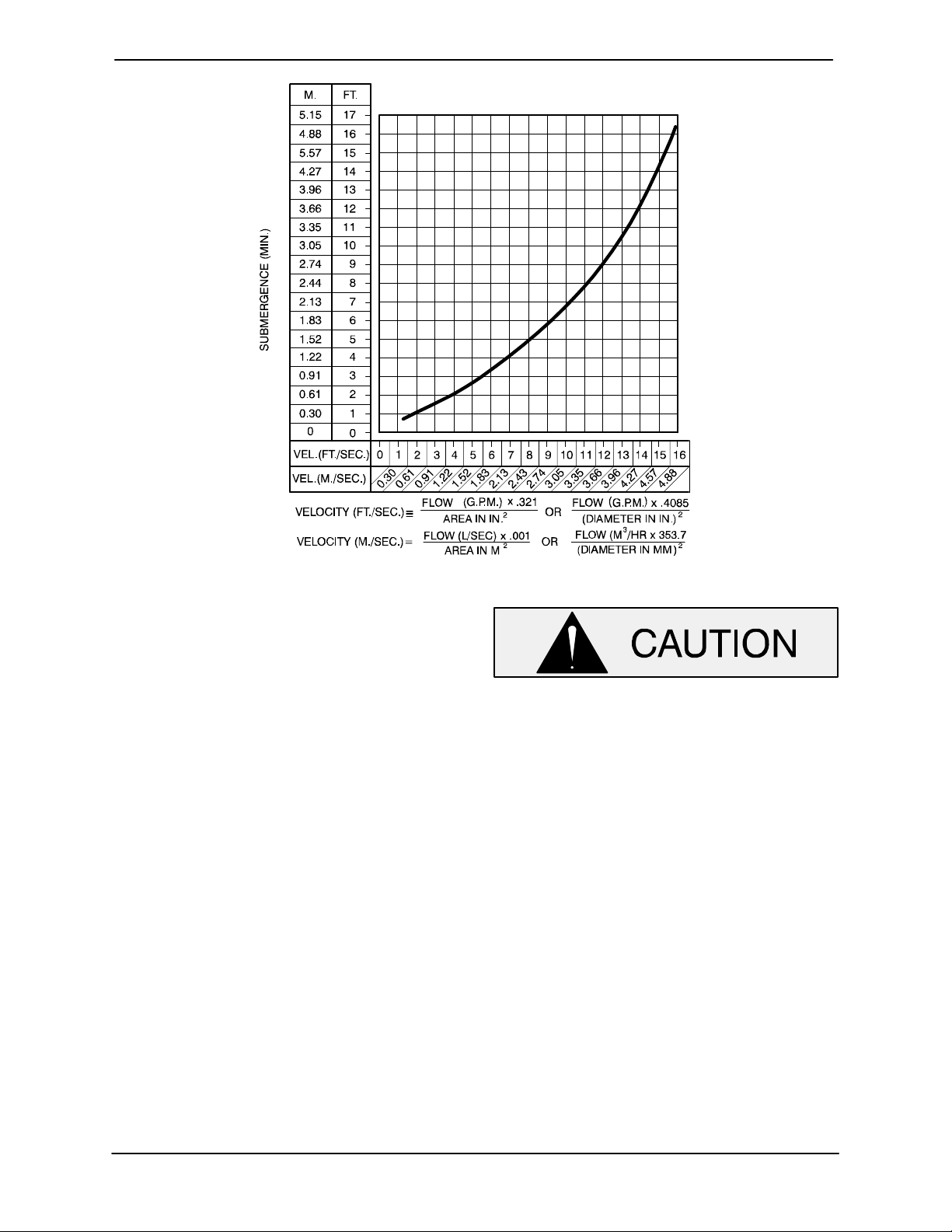
OM-06592 10 SERIES
Figure B-1. Recommended Minimum Suction Line Submergence vs. Velocity
DISCHARGE LINES
Siphoning
Do not terminate the discharge line at a level lower
than that of the liquid being pumped unless a si
phon breaker is used in the line. Otherwise, a si
phoning action causing damage to the pump
could result.
Valves
If a throttling valve is desired in the discharge line,
use a valve as large as the largest pipe to minimize
friction losses. Never install a throttling valve in a
suction line.
A check valve in the discharge line is normally rec
ommended, but it is not necessary in low dis
charge head applications.
With high discharge heads, it is recommended that
a throttling valve and a system check valve be in
stalled in the discharge line to protect the pump
from excessive shock pressure and reverse rota
tion when it is stopped.
If the application involves a high discharge
head, gradually close the discharge
throttling valve before stopping the pump.
Bypass Lines
Self‐priming pumps are not air compressors. Dur
ing the priming cycle, air from the suction line must
be vented to atmosphere on the discharge side. If
the discharge line is open, this air will be vented
through the discharge. However, if a check valve
has been installed in the discharge line, the dis
charge side of the pump must be opened to atmos
pheric pressure through a bypass line installed be
tween the pump discharge and the check valve. A
self‐priming centrifugal pump will not prime if
there is sufficient static liquid head to hold the dis
charge check valve closed.
NOTE
The bypass line should be sized so that it does not
affect pump discharge capacity; however, the by
pass line should be at least 1 inch (25,4 mm) in di
PAGE B - 4 INSTALLATION
Page 12

10 SERIES OM-06592
ameter to minimize the chance of plugging.
In low discharge head applications (less than 30
feet (9,1 m)), it is recommended that the bypass
line be run back to the wet well, and located 6
inches below the water level or cut‐off point of the
low level pump. In some installations, this bypass
outline may be terminated with a six‐to‐eight foot
(1,8 to 2,4 m) length of 1‐1/4 inch (31,8 mm) I.D.
smooth‐bore hose; air and liquid vented during
the priming process will then agitate the hose and
break up any solids, grease, or other substances
likely to cause clogging.
A bypass line that is returned to a wet well
must be secured against being drawn into
the pump suction inlet.
It is also recommended that pipe unions be in
stalled at each 90_ elbow in a bypass line to ease
disassembly and maintenance.
In high discharge head applications (more than
30 feet (9,1 m), an excessive amount of liquid may
be bypassed and forced back to the wet well under
the full working pressure of the pump; this will re
duce overall pumping efficiency. Therefore, it is
recommended that a Gorman‐Rupp Automatic
Air Release Valve be installed in the bypass line.
stalled anywhere in a bypass line, it must
be a full‐opening, ball‐type valve to pre
vent plugging by solids.
A manual shut‐off valve should not be
installed in any bypass line. A manual
shut‐off valve may inadvertently be left
closed during operation. A pump which
has lost prime may continue to operate
without reaching prime, causing dan
gerous overheating and possible explo
sive rupture of the pump casing. Per
sonnel could be severely injured.
Allow an over‐heated pump to cool be
fore servicing. Do not remove plates,
covers, gauges, or fittings from an over‐
heated pump. Liquid within the pump
can reach boiling temperatures, and va
por pressure within the pump can cause
parts being disengaged to be ejected
with great force. After the pump cools,
drain the liquid from the pump by re
moving the casing drain plug. Use cau
tion when removing the plug to prevent
injury to personnel from hot liquid.
Gorman‐Rupp Automatic Air Release Valves are
reliable, and require minimum maintenance. See
Automatic Air Release Valves in this section for
installation and theory of operation of the Auto
matic Air Release Valve. Consult your Gorman‐
Rupp distributor, or contact the Gorman‐Rupp
Company for selection of an Automatic Air Release
Valve to fit your application.
Except in certain specific applications (to
prevent flooding during service of an auto
matic air release valve in a below‐ground
lift station), if a manual shut‐off valve is in
AUTOMATIC AIR RELEASE VALVE
When properly installed, a Gorman‐Rupp Auto
matic Air Release Valve will permit air to escape
through the bypass line and then close automati
cally when the pump is fully primed and pumping
at full capacity.
Some leakage (1 to 5 gallons [3.8 to 19
liters] per minute) will occur when the
valve is fully closed. Be sure the bypass
line is directed back to the wet well or
tank to prevent hazardous spills.
PAGE B - 5INSTALLATION
Page 13

OM-06592 10 SERIES
Consult the manual accompanying the Air Release
Valve for additional information on valve installation
and performance.
CLEAN‐OUT
COVER
INSTALL AIR RELEASE VALVE
IN HORIZONTAL POSITION
90_ LONG
RADIUS
ELBOW
SUPPORT
BRACKET
BLEED LINE 1”
(25,4 MM) DIA. MIN.
(CUSTOMER FUR
NISHED) EXTEND 6”
(152 MM) BELOW
PUMP OFF LIQUID
LEVEL
SUCTION
LINE
Air Release Valve Installation
The Automatic Air Release Valve must be inde
pendently mounted in a horizontal position be
tween the pump discharge port and the inlet side of
the discharge check valve (see Figure B-2). The
inlet opening in the Air Release Valve is equipped
with standard 1‐inch NPT pipe threads.
DISCHARGE PIPE
DISCHARGE
CHECK VALVE
PUMP DISCHARGE
SELF‐PRIMING
CENTRIFUGAL
PUMP
WET WELL
OR SUMP
Figure B-2. Typical Automatic Air Release Valve Installation
Connect the valve outlet to a bleed line which
slopes back to the wet well or sump. The bleed line
must be the same size as the outlet opening or
larger, depending on which Air Release Valve is be
ing used. If piping is used for the bleed line, avoid
the use of elbows whenever possible.
NOTE
For multiple pump installations, it is recommended
that each Air Release Valve be fitted with an inde
pendent bleeder line directed back to the wet well.
If multiple Air Release Valves are installed in a sys
tem, do not direct bleeder lines to a common mani
fold pipe. Contact your Gorman‐Rupp distributor or
the Gorman‐Rupp Company for information about
installation of an Automatic Air Release Valve for
your specific application.
ALIGNMENT
The alignment of the pump and engine is critical for
trouble‐free mechanical operation. The driver and
pump must be mounted so that their shafts are
aligned with and parallel to each other.
When mounted at the Gorman‐Rupp factory, driver
and pump are aligned before shipment. Misalign
ment can occur in transit and handling. Pumps
should be checked, and realigned if necessary, be
fore being put into operation. Before checking
alignment, tighten the hardware securing the
pump to the base.
The axis of the drive unit must be aligned to the axis
of the pump shaft in both the horizontal and vertical
planes. Most couplings require a specific gap or
clearance between the driving and the driven
PAGE B - 6 INSTALLATION
Page 14

10 SERIES OM-06592
shafts. Refer to the coupling manufacturer's serv
ice literature for information.
This pump is furnished with a flexible coupling. To
check alignment, use a feeler gauge or a taper
gauge between the coupling halves every 90 de
grees. The coupling is in alignment when the hubs
are the same distance apart at all points.
To check parallel adjustment, lay a straightedge
across both coupling halves at the top, bottom,
and side. The coupling is in horizontal parallel
alignment when the straightedge rests evenly on
both halves of the coupling. Use a feeler gauge be
tween the coupling and the straightedge to meas
ure the amount of misalignment.
Coupling and alignment adjustments may be
made by loosening the hold‐down bolts and shift
ing the driver and/or pump, or by shimming as re
quired.
Adjusting the alignment in one direction
may alter the alignment in another direc
tion. Check each procedure after altering
alignment.
Do not operate the pump without the
coupling guard in place over the rotat
ing parts. Exposed rotating parts can
catch clothing, fingers, or tools, causing
severe injury to personnel.
PAGE B - 7INSTALLATION
Page 15

10 SERIES
OM-06592
OPERATION - SECTION C
Review all SAFETY information in Section A.
Follow the instructions on all tags, labels and
decals attached to the pump.
This pump is designed to handle most
non‐volatile, non‐flammable liquids
containing specified entrained solids.
Do not attempt to pump volatile, corro
sive or flammable liquids which may
damage the pump or endanger person
nel as a result of pump failure.
The pump end is designed to operate at
???? RPM through a gearbox with a 1.6:1
ratio at a maximum input speed of ????
RPM. Make certain that input speed does
not exceed this RPM. Operation at higher
RPM can cause pump components to be
damaged or destroyed.
not prime when dry. Extended operation of
a dry pump will destroy the seal assembly.
Add liquid to the pump casing when:
1. The pump is being put into service for the
first time.
2. The pump has not been used for a consider
able length of time.
3. The liquid in the pump casing has evapo
rated.
Once the pump casing has been filled, the pump
will prime and reprime as necessary.
After filling the pump casing, reinstall
and tighten the fill plug. Do not attempt
to operate the pump unless all connect
ing piping is securely installed. Other
wise, liquid in the pump forced out un
der pressure could cause injury to per
sonnel.
To fill the pump, remove the pump casing fill cover
or fill plug in the top of the casing, and add clean
liquid until the casing is filled. Replace the fill cover
or fill plug before operating the pump.
PRIMING
Install the pump and piping as described in IN
STALLATION. Make sure that the piping connec
tions are tight, and that the pump is securely
mounted. Check that the pump is properly lubri
cated (see LUBRICATION in MAINTENANCE
AND REPAIR).
This pump is self‐priming, but the pump should
never be operated unless there is liquid in the
pump casing.
Never operate this pump unless there is
liquid in the pump casing. The pump will
OPERATION PAGE C - 1
STARTING
Consult the operations manual furnished with the
engine.
OPERATION
Gearbox Check
Check the gearbox lubrication before operation,
and periodically thereafter. See the gearbox man
ufacturer's literature for recommendations.
Lines With a Bypass
If a Gorman‐Rupp Automatic Air Release Valve has
been installed, the valve will automatically open to
Page 16

OM-06592 10 SERIES
allow the pump to prime, and automatically close
after priming is complete (see INSTALLATION for
Air Release Valve operation).
If the bypass line is open, air from the suction line
will be discharged through the bypass line back to
the wet well during the priming cycle. Liquid will
then continue to circulate through the bypass line
while the pump is in operation.
Lines Without a Bypass
Open all valves in the discharge line and start the
power source. Priming is indicated by a positive
reading on the discharge pressure gauge or by a
quieter operation. The pump may not prime imme
diately because the suction line must first fill with
liquid. If the pump fails to prime within five minutes,
stop it and check the suction line for leaks.
After the pump has been primed, partially close the
discharge line throttling valve in order to fill the line
slowly and guard against excessive shock pres
sure which could damage pipe ends, gaskets,
sprinkler heads, and any other fixtures connected
to the line. When the discharge line is completely
filled, adjust the throttling valve to the required flow
rate.
Liquid Temperature And Overheating
The maximum liquid temperature for this pump is
160_F (71_C). Do not apply it at a higher operating
temperature.
Overheating can occur if operated with the valves
in the suction or discharge lines closed. Operating
against closed valves could bring the liquid to a
boil, build pressure, and cause the pump to rup
ture or explode. If overheating occurs, stop the
pump and allow it to cool before servicing it. Refill
the pump casing with cool liquid.
Allow an over‐heated pump to cool be
fore servicing. Do not remove plates,
covers, gauges, or fittings from an over‐
heated pump. Liquid within the pump
can reach boiling temperatures, and va
por pressure within the pump can cause
parts being disengaged to be ejected
with great force. After the pump cools,
drain the liquid from the pump by re
moving the casing drain plug. Use cau
tion when removing the plug to prevent
injury to personnel from hot liquid.
Do not operate the pump against a
closed discharge throttling valve for
long periods of time. If operated against
a closed discharge throttling valve,
pump components will deteriorate, and
the liquid could come to a boil, build
pressure, and cause the pump casing to
rupture or explode.
Leakage
No leakage should be visible at pump mating sur
faces, or at pump connections or fittings. Keep all
line connections and fittings tight to maintain maxi
mum pump efficiency.
As a safeguard against rupture or explosion due to
heat, this pump is equipped with a pressure relief
valve which will open if vapor pressure within the
pump casing reaches a critical point. If overheating
does occur, stop the pump immediately and allow
it to cool before servicing it. Approach any over
heated pump cautiously. It is recommended that
the pressure relief valve assembly be replaced at
each overhaul, or any time the pump casing over
heats and activates the valve. Never replace this
valve with a substitute which has not been speci
fied or provided by the Gorman‐Rupp Company.
Strainer Check
If a suction strainer has been shipped with the
pump or installed by the user, check the strainer
regularly, and clean it as necessary. The strainer
should also be checked if pump flow rate begins to
drop. If a vacuum suction gauge has been in
stalled, monitor and record the readings regularly
to detect strainer blockage.
OPERATIONPAGE C - 2
Page 17

10 SERIES
OM-06592
Never introduce air or steam pressure into the
pump casing or piping to remove a blockage. This
could result in personal injury or damage to the
equipment. If backflushing is absolutely neces
sary, liquid pressure must be limited to 50% of the
maximum permissible operating pressure shown
on the pump performance curve (see Section E,
Page 1).
Pump Vacuum Check
With the pump inoperative, install a vacuum gauge
in the system, using pipe dope on the threads.
Block the suction line and start the pump. At oper
ating speed the pump should pull a vacuum of 20
inches (508,0 mm) or more of mercury. If it does
not, check for air leaks in the seal, gasket, or dis
charge valve.
Open the suction line, and read the vacuum gauge
with the pump primed and at operating speed.
Shut off the pump. The vacuum gauge reading will
immediately drop proportionate to static suction
lift, and should then stabilize. If the vacuum reading
falls off rapidly after stabilization, an air leak exists.
Before checking for the source of the leak, check
the point of installation of the vacuum gauge.
STOPPING
Never halt the flow of liquid suddenly. If the liquid
being pumped is stopped abruptly, damaging
shock waves can be transmitted to the pump and
piping system. Close all connecting valves slowly.
If the application involves a high discharge
head, gradually close the discharge
throttling valve before stopping the pump.
After stopping the pump, disconnect the engine or
lock it out to ensure that the pump will remain inop
erative.
Cold Weather Preservation
In below freezing conditions, drain the pump to
prevent damage from freezing. Also, clean out any
solids by flushing with a hose. Operate the pump
for approximately one minute; this will remove any
remaining liquid that could freeze the pump rotat
ing parts. If the pump will be idle for more than a
few hours, or if it has been pumping liquids con
taining a large amount of solids, drain the pump,
and flush it thoroughly with clean water. To prevent
large solids from clogging the drain port and pre
venting the pump from completely draining, insert
a rod or stiff wire in the drain port, and agitate the
liquid during the draining process. Clean out any
remaining solids by flushing with a hose.
BEARING TEMPERATURE CHECK
Bearings normally run at higher than ambient tem
peratures because of heat generated by friction.
Temperatures up to 160_F (71_C) are considered
normal for bearings, and they can operate safely to
at least 180_F (82_C).
Checking bearing temperatures by hand is inaccu
rate. Bearing temperatures can be measured ac
curately by placing a contact‐type thermometer
against the housing. Record this temperature for
future reference.
A sudden increase in bearing temperatures is a
warning that the bearings are at the point of failing
to operate properly. Make certain that the bearing
lubricant is of the proper viscosity and at the cor
rect level (see LUBRICATION in Section E). Bear
ing overheating can also be caused by shaft
misalignment and/or excessive vibration.
When pumps are first started, the bearings may
seem to run at temperatures above normal. Con
tinued operation should bring the temperatures
down to normal levels.
OPERATION PAGE C - 3
Page 18

TROUBLESHOOTING - SECTION D
Review all SAFETY information in Section A.
Before attempting to open or service the
pump:
1. Familiarize yourself with this manual.
2. Shut down the engine and remove
the key to ensure that the pump will
remain inoperative.
3. Allow the pump to completely cool if
overheated.
4. Check the temperature before open
ing any covers, plates, or plugs.
5. Close the suction and discharge
valves.
6. Vent the pump slowly and cautiously.
7. Drain the pump.
OM-0659210 SERIES
TROUBLE POSSIBLE CAUSE PROBABLE REMEDY
PUMP FAILS TO
PRIME
PUMP STOPS OR
FAILS TO DELIVER
RATED FLOW OR
PRESSURE
Not enough liquid in casing.
Suction check valve contaminated or
damaged.
Air leak in suction line. Correct leak.
Lining of suction hose collapsed. Replace suction hose.
Leaking or worn seal or pump gasket. Check pump vacuum. Replace
Suction lift or discharge head too high. Check piping installation and install
Strainer clogged. Check strainer and clean if neces
Air leak in suction line. Correct leak.
Lining of suction hose collapsed. Replace suction hose.
Leaking or worn seal or pump gasket. Check pump vacuum. Replace
Strainer clogged. Check strainer and clean if neces
Add liquid to casing. See PRIMING.
Clean or replace check valve.
leaking or worn seal or gasket.
bypass line if needed. See INSTAL
LATION.
sary.
leaking or worn seal or gasket.
sary.
TROUBLESHOOTING PAGE D - 1
Page 19

OM-06592 10 SERIES
TROUBLE POSSIBLE CAUSE PROBABLE REMEDY
PUMP STOPS OR
FAILS TO DELIVER
RATED FLOW OR
PRESSURE (cont.)
PUMP REQUIRES
TOO MUCH
POWER
PUMP CLOGS
FREQUENTLY
Suction intake not submerged at
proper level or sump too small.
Impeller or other wearing parts worn
or damaged.
Discharge head too high.
Suction lift too high.
Pump speed too slow. Check engine output; consult en
Pump speed too high. Check engine output.
Discharge head too low.
Bearing(s) frozen. Disassemble pump and check bear
Discharge flow too slow.
Check installation and correct
submergence as needed.
Replace worn or damaged parts.
Check that impeller is properly
centered and rotates freely.
Free impeller of debris.Impeller clogged.
Install bypass line.
Measure lift w/vacuum gauge. Re
duce lift and/or friction losses in
suction line.
gine operation manual.
Adjust discharge valve.
Dilute if possible.Liquid solution too thick.
ing(s).
Open discharge valve fully to in
crease flow rate, and run engine at
maximum governed speed.
Suction check valve or foot valve
clogged or binding.
Liquid solution too thick.
EXCESSIVE NOISE Cavitation in pump. Reduce suction lift and/or friction
Pumping entrained air.
Impeller clogged or damaged.
BEARINGS RUN
TOO HOT
Bearing temperature is high, but
within limits.
Low or incorrect lubricant.
Suction and discharge lines not prop
erly supported.
Clean valve.
Dilute if possible.
losses in suction line. Record vac
uum and pressure gauge readings
and consult local representative or
factory.
Locate and eliminate source of air
bubble.
Secure mounting hardware.Pump or drive not securely mounted.
Clean out debris; replace damaged
parts.
Check bearing temperature regu
larly to monitor any increase.
Check for proper type and level of
lubricant.
Check piping installation for proper
support.
Align drive properly.Drive misaligned.
TROUBLESHOOTINGPAGE D - 2
Page 20

OM-0659210 SERIES
PREVENTIVE MAINTENANCE
Since pump applications are seldom identical, and
pump wear is directly affected by such things as
the abrasive qualities, pressure and temperature
of the liquid being pumped, this section is intended
only to provide general recommendations and
practices for preventive maintenance. Regardless
of the application however, following a routine pre
ventive maintenance schedule will help assure
trouble‐free performance and long life from your
Gorman‐Rupp pump. For specific questions con
cerning your application, contact your Gorman‐
Rupp distributor or the Gorman‐Rupp Company.
Record keeping is an essential component of a
good preventive maintenance program. Changes
in suction and discharge gauge readings (if so
equipped) between regularly scheduled inspec
tions can indicate problems that can be corrected
before system damage or catastrophic failure oc
curs. The appearance of wearing parts should also
be documented at each inspection for comparison
as well. Also, if records indicate that a certain part
(such as the seal) fails at approximately the same
duty cycle, the part can be checked and replaced
before failure occurs, reducing unscheduled down
time.
For new applications, a first inspection of wearing
parts at 250 hours will give insight into the wear rate
for your particular application. Subsequent inspec
tions should be performed at the intervals shown
on the chart below. Critical applications should be
inspected more frequently.
Preventive Maintenance Schedule
Service Interval*
Item
General Condition (Temperature, Unusual
Noises or Vibrations, Cracks, Leaks,
Loose Hardware, Etc.) I
Pump Performance (Gauges, Speed, Flow) I
Bearing Lubrication I R
Seal Lubrication (And Packing Adjustment,
If So Equipped) I R
V‐Belts (If So Equipped) I
Air Release Valve Plunger Rod (If So Equipped) I C
Front Impeller Clearance (Wear Plate) I
Rear Impeller Clearance (Seal Plate) I
Check Valve I
Pressure Relief Valve (If So Equipped) C
Pump and Driver Alignment I
Shaft Deflection I
Bearings I
Bearing Housing I
Piping I
Driver Lubrication - See Mfgr's Literature
Daily Weekly Monthly Semi‐
Annually
Annually
Legend:
I = Inspect, Clean, Adjust, Repair or Replace as Necessary
C = Clean
R = Replace
* Service interval based on an intermittent duty cycle equal to approximately 4000 hours annually.
Adjust schedule as required for lower or higher duty cycles or extreme operating conditions.
TROUBLESHOOTING PAGE D - 3
Page 21

10 SERIES OM-06592
PUMP MAINTENANCE AND REPAIR ‐ SECTION E
MAINTENANCE AND REPAIR OF THE WEARING PARTS OF THE PUMP WILL MAINTAIN PEAK
OPERATING PERFORMANCE.
STANDARD PERFORMANCE FOR PUMP MODEL 112D60-B-TCD914L6
Based on 70_F (21_C) clear water at sea level
with minimum suction lift. Since pump installations
are seldom identical, your performance may be dif
ferent due to such factors as viscosity, specific
gravity, elevation, temperature, and impeller trim.
Pump speed and operating condition
points must be within the continuous per
formance range shown on the curve.
MAINTENANCE & REPAIR PAGE E - 1
Page 22

PARTS PAGE
10 SERIESOM-04624
ILLUSTRATION
Figure E-1. Pump Model 112D60-B-TCD914L6
MAINTENANCE & REPAIRPAGE E - 2
Page 23

10 SERIES OM-06592
PARTS LIST
Pump Model 112D60-B-TCD914L6
(From S/N 1520501 Up)
If your pump serial number is followed by an “N”, your pump is NOT a standard production model. Contact
the Gorman‐Rupp Company to verify part numbers.
ITEM
PART NAME PART
NO.
1 PUMP MODEL ASSY 112D60-B --- 1
2 DEUTZ TCD914L6 ENGINE 29210-729 --- 1
3 GASKET 4991G 18000 4
4 HEX NUT D14 15991 48
5 HEX HEAD CAP SCREW B1416 15991 30
6 FLANGED ELBOW S5017 --- 1
7 FLANGE 4991A 10010 2
8 COUPLING GUARD ASSY 42341-049 24150 1
9 GEAR RED DRIVE KEY N1216 15990 1
10 GEAR REDUCER 24572-207 --- 1
11 LIFTING BAIL ASSY 44713-058 24150 1
12 HEX HEAD CAP SCREW 22645-164 --- 12
13 LOCK WASHER 21171-511 --- 20
14 HEX HEAD CAP SCREW B0403 15991 6
15 LOCK WASHER J04 15991 10
16 HEX NUT D04 15991 10
17 INSTRUCTION PLATE 38818-160 13000 1
18 HEX NUT D08 15991 34
19 LOCK WASHER J08 15991 34
20 ENGINE RAIL 34458-080 15080 1
21 HEX HEAD CAP SCREW B0816 15991 2
22 COMBINATION BASE 41566-726 24150 1
23 FLAT WASHER K08 15991 26
24 FUEL TANK ASSY 46711-072 --- 1
25 HEX HEAD CAP SCREW B0806 15991 26
26 ENGINE RAIL 34458-081 15080 1
27 HEX HEAD CAP SCREW B1008 15991 8
28 LOCK WASHER J10 15991 8
29 HEX HEAD CAP SCREW B0605 15991 4
30 LOCK WASHER J06 15991 4
31 HEX HEAD CAP SCREW B0807 15991 2
32 SUPPORT 34228-087 15080 1
33 FLEX COUPLING 24341-024 --- 1
34 HEX HEAD CAP SCREW B0404 15991 4
35 FLAT WASHER K04 15991 8
36 HEX NUT D16 15991 8
37 LOCK WASHER J16 15991 8
38 HEX HEAD CAP SCREW B1612 15991 6
39 FLAT WASHER K16 15991 2
40 HEX HEAD CAP SCREW B1609 15991 2
41 SUPPORT ASSY 41881-570 24150 2
42 HEX HEAD CAP SCREW B0811 15991 2
43 TENSIONER BAR 11165 24000 2
44 NOZZLE SUPPORT ASSY 41881-571 24150 1
45 HEX HEAD CAP SCREW B1415 15991 18
46 DISCH ADAPTER FLANGE 14275 10010 1
NUMBER
MAT'L
CODE
QTY ITEM
NO.
47 PIPE PLUG P32 10009 1
48 T‐BOLT CLAMP 26518-166 --- 1
49 HUMP CONNECTOR 26413-001 --- 1
50 T‐BOLT CLAMP 26518-164 --- 7
51 ELBOW 29284-039 --- 1
52 WEATHER CAP S2021 --- 1
53 HEX HEAD CAP SCREW B0504 15991 4
54 LOCK WASHER J05 15991 4
55 HEX NUT D05 15991 4
56 FLAT WASHER K05 15991 4
57 MUFFLER BRKT WLDMNT 41888-282 24150 1
58 MUFFLER 29334-104 --- 1
59 MUFFLER BRACKET 29334-286 --- 2
60 MUFFLER CLAMP S2227 --- 2
61 EXHAUST ELBOW 29334-382 --- 1
62 EXHAUST FLANGE ASSY 46281-007 24150 1
63 INSERT 29284-042 --- 1
64 AIR INTAKE ELBOW 29284-033 --- 2
65 AIR INTAKE PIPE 31417-066 15210 1
66 CONNECTOR S1447 --- 2
67 HOSE ASSY 46341-803 --- 2
68 FUEL RETURN ASSY 46331-014 24030 1
69 PIPE ELBOW R04 11999 1
70 POS BATT CABLE 47311-113 --- 1
71 NEG BATT CABLE 47311-133 --- 1
72 BATTERY BOX ASSY 42432-003 --- 1
73 12V BATTERY SEE OPTIONS REF
74 BELT GUARD KIT 29277-055 --- 1
75 AIR INTAKE PIPE 31417-065 15000 2
76 AIR FILTER BRACKET 41888-283 24150 1
NOT SHOWN:
OPTIONAL:
PART NAME PART
NUMBER
CAP SCREW M10X1.5X60 22645-170 --- 8
SPRING STRAP 33245-023 15099 2
MUFFLER GUARD 34611-019 15080 1
SPACER SPRING 24641-014 --- 2
STRAPPING 12961-203 --- 2
BUCKLE 12961-213 --- 2
CONT PANEL INST KIT 48122-503 --- 1
WHEEL KIT GRP30-10E --- 1
DISCHARGE DECAL 6588BJ --- 1
GUARD WARNING DECAL 38816-063 --- 1
CAUTION DECAL 2613FJ --- 1
WARNING DECAL 2613FE --- 1
SUCTION DECAL 6588AG --- 1
12V BATTERY 29331-506 --- 1
MAT'L
CODE
QTY
INDICATES PARTS RECOMMENDED FOR STOCK
MAINTENANCE & REPAIR PAGE E - 3
Page 24

ILLUSTRATION
10 SERIESOM-04624
Figure E-2. Pump Model 112D60-B-TCD914L6 (Cont'd)
MAINTENANCE & REPAIRPAGE E - 4
Page 25

10 SERIES OM-06592
PARTS LIST
Pump Model 112D60-B-TCD914L6 (Cont'd)
(From S/N Up)
If your pump serial number is followed by an “N”, your pump is NOT a standard production model. Contact
the Gorman‐Rupp Company to verify part numbers.
ITEM
PART NAME PART
NO.
1 PUMP MODEL ASSY 112D60-B --- 1
2 DEUTZ TCD914L6 ENGINE 29210-729 --- 1
3 GASKET 4991G 18000 4
4 HEX NUT D14 15991 48
5 HEX HEAD CAP SCREW B1416 15991 30
6 FLANGED ELBOW S5017 --- 1
7 FLANGE 4991A 10010 2
8 COUPLING GUARD ASSY 42341-049 24150 1
9 GEAR RED DRIVE KEY N1216 15990 1
10 GEAR REDUCER 24572-207 --- 1
11 LIFTING BAIL ASSY 44713-058 24150 1
12 HEX HEAD CAP SCREW 22645-164 --- 12
13 LOCK WASHER 21171-511 --- 20
14 HEX HEAD CAP SCREW B0403 15991 6
15 LOCK WASHER J04 15991 10
16 HEX NUT D04 15991 10
17 INSTRUCTION PLATE 38818-160 13000 1
18 HEX NUT D08 15991 34
19 LOCK WASHER J08 15991 34
20 ENGINE RAIL 34458-080 15080 1
21 HEX HEAD CAP SCREW B0816 15991 2
22 COMBINATION BASE 41566-726 24150 1
23 FLAT WASHER K08 15991 26
24 FUEL TANK ASSY 46711-072 --- 1
25 HEX HEAD CAP SCREW B0806 15991 26
26 ENGINE RAIL 34458-081 15080 1
27 HEX HEAD CAP SCREW B1008 15991 8
28 LOCK WASHER J10 15991 8
29 HEX HEAD CAP SCREW B0605 15991 4
30 LOCK WASHER J06 15991 4
31 HEX HEAD CAP SCREW B0807 15991 2
32 SUPPORT 34228-087 15080 1
33 FLEX COUPLING 24341-024 --- 1
34 HEX HEAD CAP SCREW B0404 15991 4
35 FLAT WASHER K04 15991 8
36 HEX NUT D16 15991 8
37 LOCK WASHER J16 15991 8
38 HEX HEAD CAP SCREW B1612 15991 6
39 FLAT WASHER K16 15991 2
40 HEX HEAD CAP SCREW B1609 15991 2
41 SUPPORT ASSY 41881-570 24150 2
42 HEX HEAD CAP SCREW B0811 15991 2
43 TENSIONER BAR 11165 24000 2
44 NOZZLE SUPPORT ASSY 41881-571 24150 1
45 HEX HEAD CAP SCREW B1415 15991 18
46 DISCH ADAPTER FLANGE 14275 10010 1
NUMBER
MAT'L
CODE
QTY ITEM
NO.
47 PIPE PLUG P32 10009 1
48 T‐BOLT CLAMP 26518-166 --- 1
49 HUMP CONNECTOR 26413-001 --- 1
50 T‐BOLT CLAMP 26518-164 --- 7
51 ELBOW 29284-039 --- 1
52 WEATHER CAP S2021 --- 1
53 HEX HEAD CAP SCREW B0504 15991 4
54 LOCK WASHER J05 15991 4
55 HEX NUT D05 15991 4
56 FLAT WASHER K05 15991 4
57 MUFFLER BRKT WLDMNT 41888-282 24150 1
58 MUFFLER 29334-104 --- 1
59 MUFFLER BRACKET 29334-286 --- 2
60 MUFFLER CLAMP S2227 --- 2
61 EXHAUST ELBOW 29334-382 --- 1
62 EXHAUST FLANGE ASSY 46281-007 24150 1
63 INSERT 29284-042 --- 1
64 AIR INTAKE ELBOW 29284-033 --- 2
65 AIR INTAKE PIPE 31417-066 15210 1
66 CONNECTOR S1447 --- 2
67 HOSE ASSY 46341-803 --- 2
68 FUEL RETURN ASSY 46331-014 24030 1
69 PIPE ELBOW R04 11999 1
70 POS BATT CABLE 47311-113 --- 1
71 NEG BATT CABLE 47311-133 --- 1
72 BATTERY BOX ASSY 42432-003 --- 1
73 12V BATTERY SEE OPTIONS REF
74 BELT GUARD KIT 29277-055 --- 1
75 AIR INTAKE PIPE 31417-065 15000 2
76 AIR FILTER BRACKET 41888-283 24150 1
NOT SHOWN:
OPTIONAL:
PART NAME PART
NUMBER
CAP SCREW M10X1.5X60 22645-170 --- 8
SPRING STRAP 33245-023 15099 2
MUFFLER GUARD 34611-019 15080 1
SPACER SPRING 24641-014 --- 2
STRAPPING 12961-203 --- 2
BUCKLE 12961-213 --- 2
CONT PANEL INST KIT 48122-503 --- 1
WHEEL KIT GRP30-10E --- 1
DISCHARGE DECAL 6588BJ --- 1
GUARD WARNING DECAL 38816-063 --- 1
CAUTION DECAL 2613FJ --- 1
WARNING DECAL 2613FE --- 1
SUCTION DECAL 6588AG --- 1
12V BATTERY 29331-506 --- 1
MAT'L
CODE
QTY
INDICATES PARTS RECOMMENDED FOR STOCK
MAINTENANCE & REPAIR PAGE E - 5
Page 26

ILLUSTRATION
10 SERIESOM-04624
Figure E-3. Pump End Assembly 112D60-B
MAINTENANCE & REPAIRPAGE E - 6
Page 27

10 SERIES OM-06592
PARTS LIST
Pump End Assembly 112D60-B
ITEM
PART NAME PART
NO.
1 PUMP CASING 38222-702 10010 1
2 PEDESTAL 38257-511 10010 1
3 IMPELLER SHAFT 38512-519 16040 1
4 BALL BEARING 23421-417 --- 1
5 BALL BEARING 23275-017 --- 1
6 BEARING COVER 38322-419 10010 1
7 OUTBOARD OIL SEAL 25258-851 --- 1
7A INBOARD OIL SEAL 25258-851 --- 1
8 SEAL PLATE 38272-706 10010 1
9 O‐RING 25152-256 --- 1
10 SEAL ASSY 46512-259 --- 1
11 IMPELLER 38615-710 11030 1
12 IMPELLER KEY N0812 15990 1
13 ROLL PIN S2197 --- 1
14 SOCKET HD CAP SCREW BD1206 15990 1
15 IMPELLER WASHER 31167-012 15030 1
16 WEAR PLATE 38691-808 11030 1
17 WEAR PLATE O‐RING 25152-283 --- 1
17A SEAL PLATE O‐RING 26152-283 --- 1
18 O‐RING 25152-278 --- 1
19 SUCTION ELBOW 38647-910 10010 1
20 PEDESTAL FOOT 38151-002 10010 1
21 SUCT ELBOW SUPPORT 41881-258 24150 1
22 SUCTION CHK VLV ASSY 46421-035 --- 1
-HEX HD CAP SCREW B0606 15991 2
-PIPE PLUG P08 15079 2
-FLAT WASHER KB08 17000 2
-PIVOT CAP 38141-003 11060 2
-CHECK VALVE BODY 38341-806 10010 1
-T‐TYPE LK WASHER AK06 15991 2
-CHK VALVE ASSY 46411-068 24010 1
23 GASKET 38688-015 20000 1
24 GASKET 38682-016 20000 1
25 COVER PLATE ASSY 48271-025 --- 1
-CLEANOUT COVER NOT AVAILABLE 1
-WARNING PLATE 38816-097-13990 1
-DRIVE SCREW BM#04-03 17000 2
26 SQUARE HEAD BOLT A1011 15991 8
27 CLAMP BAR SCREW 31912-009 15000 2
28 CLAMP BAR 38111-310 11010 2
29 LOCK WASHER J12 15991 26
30 HEX HD CAP SCREW B1206 15991 2
31 STUD C1216 15991 4
32 HEX NUT D12 15991 4
33 GASKET 2751G 18000 1
34 CONCENTRIC REDUCER 38642-620 10000 1
35 HEX HD CAP SCREW B1416 15991 12
36 LOCK WASHER J14 15991 12
37 HEX NUT D14 15991 12
NUMBER
MAT'L
CODE
QTY ITEM
NO.
38 WAVE WASHER 23963-333 --- 3
39 VICTAULIC CPLG 25552-214 --- 1
40 COVER PLATE ASSY 48271-026 --- 1
41 COVER PLATE CLAMP 12872 11010 2
42 CLAMP SCREW 2536 24000 2
43 TAP BOLT 21612-199 --- 4
44 HEX JAM NUT AT08 15991 4
45 HEX HD CAP SCREW B1209 15991 8
46 PIPE PLUG P08 15079 4
47 PIPE PLUG P16 10009 1
48 LOCK WASHER J06 15991 2
49 HEX HD CAP SCREW B0610 15991 2
50 BRG CAVITY AIR VENT S1703 --- 2
50A SEAL CAVITY AIR VENT S1703 --- 2
51 LOCK WASHER J08 15991 10
52 HEX HD CAP SCREW B0808 15991 6
53 PIPE PLUG P06 15079 6
54 BOTTLE OILER BRKT 41881-617 24150 1
55 FLAT WASHER K12 15991 2
56 BOTTLE OILER 26713-004 --- 1
57 BARBED ELBOW 26523-506 --- 1
58 MALE CONNECTOR 26523-409 --- 1
59 HOSE 31411-227 19360 1
60 HOSE CLAMP 26518-642 --- 2
61 OIL LEVEL DECAL 38816-123 --- 1
62 DRIVE KEY N1020 15990 1
63 O‐RING S1874 --- 1
64 SIGHT GAGE 26714-011 --- 1
65 HEX HD CAP SCREW B1210 15991 14
66 PIPE PLUG P24 10009 3
67 STUD C0814 15991 4
68 HEX NUT D08 15991 4
69 PRESS RELIEF VALVE 26662-005 --- 1
NOT SHOWN:
PART NAME PART
NUMBER
-FILL COVER PLATE NOT AVAILABLE 1
-WARNING PLATE 38816-097 13990 1
-DRIVE SCREW BM#04-03 17000 2
NAME PLATE 2613D 13990 1
ROTATION DECAL 2613M --- 1
STRAINER 46641-012 24150 1
DRIVE SCREW BM #04-03 17000 4
LUBE DECAL 38816-079 --- 1
WARNING DECAL 38816-302 --- 1
G‐R DECAL GR-06 --- 1
INSTRUCTION LABEL 2613DK --- 1
WARNING DECAL 2613FE --- 1
INSTRUCTION TAG 38817-011 --- 1
INSTRUCTION TAG 38817-024 --- 1
SUCTION STICKER 6588AG --- 1
DISCHARGE STICKER 6588BJ --- 1
MAT'L
CODE
QTY
INDICATES PARTS RECOMMENDED FOR STOCK
MAINTENANCE & REPAIR PAGE E - 7
Page 28

10 SERIESOM-06592
PUMP AND SEAL DISASSEMBLY AND REASSEMBLY
Review all SAFETY information in Section A.
Follow the instructions on all tags, label and de
cals attached to the pump.
This pump requires little service due to its rugged,
minimum‐maintenance design. However, if it be
comes necessary to inspect or replace the wearing
parts, follow these instructions which are keyed to
the illustrations (see Figures E‐1 through E‐3) and
the accompanying parts lists.
Before attempting to service the pump, shut down
the engine and remove the key to ensure that the
pump will remain inoperative. Close all valves in the
suction and discharge lines.
For engine disassembly and repair, consult the lit
erature supplied with the engine, or contact your
local engine representative.
Suction Check Valve Disassembly
(Figure E‐1)
Before attempting to service the pump, remove the
lowermost pipe plug (66, Figure E‐3) and drain the
pump. Clean and reinstall the drain plug.
(Figure E‐3)
To service the suction check valve assembly (22),
loosen the cover clamp screw (42) and remove the
cover plate clamp (41) securing the cover plate as
sembly (40) to the suction elbow (19). Remove the
cover plate gasket (23) and replace as required.
Reach through the access opening and remove
the hardware and pivot caps securing the check
valve to the check valve body. Remove the check
valve through the access opening.
Inspect the check valve for wear or damage. If re
placement is required, remove the flat washers
from the pivot arm. Tie and tag the washers for fu
ture reference.
If the check valve body needs replaced, remove
the suction piping. See Figure 1 and remove the
hardware (4, 5 and 45) securing the adaptor flange
(46) to the suction elbow (19, Figure 3). Remove
the adaptor flange and gasket (3).
Before attempting to open or service the
pump:
1. Familiarize yourself with this man
ual.
2. Shut down the engine and remove
the key to ensure that the pump will
remain inoperative.
3. Allow the pump to completely cool
if overheated.
4. Check the temperature before
opening any covers, plates, or
plugs.
5. Close the suction and discharge
valves.
6. Vent the pump slowly and cau
tiously.
7. Drain the pump.
Remove the “Victaulic” coupling (39) and separate
the valve body from the suction elbow. Inspect the
rubber “Victaulic” gasket for damage and replace
as required.
If no further disassembly is required, see Suction
Check Valve Assembly.
Suction Elbow and Wear Plate Removal
(Figure E‐3)
Service to the wear plate (16), impeller (11) or seal
assembly (10), can be accomplished from either
side of the pump casing (1). The following instruc
tions are based on service from the suction side of
the pump.
Install a 3/4-10 UNC-2B lifting eye (not supplied)
in the tapped hole located in the suction elbow. Be
sure the eye bolt is fully engaged before attaching
a hoist. Support the suction elbow using a suitable
hoist and sling. The hoist is used to support the
MAINTENANCE & REPAIRPAGE E - 8
Page 29

OM-0659210 SERIES
suction elbow only, do not try to lift the pump. Re
move the hardware securing the elbow support
(21) and pedestal foot (20) to the base. Tie and tag
any leveling shims used under the mounting feet to
ease reassembly.
Before attempting to remove the suction elbow,
support the pump body by wedging a block of
wood under the pump casing.
Remove the hardware (29, 32 and 45) securing the
pedestal foot and suction elbow (19) to the pump
casing. Use the jacking screws (65) to press the
suction elbow out of the pump casing and sepa
rate the assemblies.
Inspect the wear plate (16) and O‐ring (17) for dam
age or wear. If the wear plate must be replaced, re
move the hardware (51 and 68) from the wear plate
studs (67). Loosen the jam nuts (44) and then tight
en the adjusting screws (43) until the wear plate is
free. Inspect the suction head O‐ring (18) for dam
age and replace as required.
Impeller Removal
(Figure E‐3)
(Figures E‐3 and E‐4)
Before removing the seal, disconnect the hose (59)
from the connector (58) and plug the tube to stop
the flow of oil from the bottle oiler (56). Remove the
connector (58) and allow the seal cavity to drain.
NOTE
The oil will not drain below the hole for the connec
tor. To drain the remaining oil from the seal cavity,
remove one of the pipe plugs (53) and drain the re
maining oil into a pan.
Remove the seal spring. Slide the shaft sleeve (70)
and rotating portion of the seal off the shaft as a
unit. Apply oil to the sleeve and work it up under the
bellows. Slide the rotating portion of the seal off the
shaft sleeve.
Remove the shaft sleeve O‐ring (71).
Use a pair of stiff wires with hooked ends to remove
the stationary element, seat and O‐rings from the
seal plate.
Clean the seal cavity and shaft with a soft cloth
soaked in cleaning solvent.
Before attempting to remove the impeller, immobi
lize the impeller by wedging a block of wood be
tween the vanes and the pump casing. Remove
the impeller capscrew, washer and roll pin (13, 14
and 15). Remove the wood block and install two
3/8-16 UNC-2B capscrews (not supplied) in the
tapped holes in the impeller hub. Use a suitable
puller to remove the impeller from the shaft (3). Re
tain the impeller key (12).
Remove the impeller adjusting shims (not shown).
For ease of reassembly, tie and tag the shims or
measure and record thickness.
Seal Removal and Disassembly
NOTE
There is an air filled cavity with an open drain hole
toward the bottom of the pedestal directly behind
the seal plate (55). If oil escapes from the drain
hole, the seal plate O‐ring (52) has failed and re
moval of the seal plate is required. The drain hole is
tapped, but do not install a pipe plug in the drain
hole..
Most cleaning solvents are toxic and
flammable. Use them only in a well ven
tilated area free from excessive heat,
sparks, and flame. Read and follow all
precautions printed on solvent contain
ers.
If no further disassembly is required, see Seal
Reassembly and Installation.
Pump Disassembly
(Figure E‐3)
Remove the discharge piping. If disassembly is re
quired, remove the hardware (35, 36 and 37) se
curing the discharge spool flange (34) and flange
gasket (33) to the pump casing (1).
Remove the hardware (29, 55 and 56) securing the
bottle oiler bracket (54) to the pedestal (2). Use a
suitable hoist and sling to support the pump cas
MAINTENANCE & REPAIR PAGE E - 9
Page 30

10 SERIESOM-06592
ing, and remove the remaining hardware (29 and
65). Separate the casing from the pedestal (2).
Remove the seal plate O‐ring (22).
Separate the seal plate (8) from the pedestal by re
moving the hardware (48 and 49). Remove the seal
plate O‐ring (9).
To separate the pedestal from the engine, remove
the hardware (15, 16, 29, 30 and 35, Figure E-1)
securing the coupling guard assembly (8, Figure
E-1) and remove the guard. Remove the separate
the halves of the coupling (33, Figure E-1) and re
move the half from the impeller shaft (3). Remove
the drive key (62).
Install a lifting eye (not supplied) in the 3/8-18 NPT
tapped hole in the top of the pedestal. Be sure the
eye is fully engaged before attaching a hoist. Re
move the mounting hardware (36, 37 and 38, Fig
ure E-1) and separate the pedestal from the base.
Tie and tag any shims used under the mounting
foot.
Place a block of wood against the impeller end of
the shaft (3) and tap the shaft and assembled bear
ings (4 and 5) from the pedestal bore. Be careful
not to damage the shaft.
Inspect the oil seal (7A) and, if replacement is re
quired, press it from the pedestal.
After removing the shaft and bearings, clean and
inspect the bearings in place as follows.
To prevent damage during removal from
the shaft, it is recommended that bearings
be cleaned and inspected in place. It is
strongly recommended that the bearings
be replaced any time the shaft and bear
ings are removed.
Clean the pedestal, shaft and all component parts
(except the bearings) with a soft cloth soaked in
cleaning solvent. Inspect the parts for wear or dam
age and replace as necessary.
Shaft and Bearing Removal and Disassembly
(Figure E‐3)
When the pump is properly operated and main
tained, the pedestal should not require disassem
bly. Disassemble the shaft and bearings only
when there is evidence of wear or damage.
Shaft and bearing disassembly in the field
is not recommended. These operations
should be performed only in a properly‐
equipped shop by qualified personnel.
Before opening the pedestal, drain the lubricant
from the pedestal by removing the drain plug (49).
Clean and reinstall the plug.
Remove the hardware (51 and 52) securing the
bearing cover (6) to the pedestal. Remove the
wave washer (38) and O‐ring (63). Inspect the oil
seal (7) and, if replacement is required, press it
from the bearing cover.
Most cleaning solvents are toxic and
flammable. Use them only in a well ven
tilated area free from excessive heat,
sparks, and flame. Read and follow all
precautions printed on solvent contain
ers.
Clean the bearings thoroughly in fresh cleaning
solvent. Dry the bearings with filtered compressed
air and coat with light oil.
Bearings must be kept free of all dirt and
foreign material. Failure to do so will great
ly shorten bearing life. Do not spin dry
bearings. This may scratch the balls or
races and cause premature bearing fail
ure.
Rotate the bearings by hand to check for rough
ness or binding and inspect the bearing balls. If ro
MAINTENANCE & REPAIRPAGE E - 10
Page 31

OM-0659210 SERIES
tation is rough or the bearing balls are discolored,
replace the bearings.
The bearing tolerances provide a tight press fit
onto the shaft and a snug slip fit into the pedestal.
Replace the bearings, shaft, or pedestal if the
proper bearing fit is not achieved.
If bearing replacement is required, use a bearing
puller to remove them from the shaft.
Shaft and Bearing Reassembly and Installation
(Figure E‐3)
Clean and inspect the bearings as indicated in
Shaft and Bearing Removal and Disassembly.
To prevent damage during removal from
the shaft, it is recommended that bearings
be cleaned and inspected in place. It is
strongly recommended that the bearings
be replaced any time the shaft and bear
ings are removed.
seated. This should be done quickly, in one con
tinuous motion, to prevent the bearings from cool
ing and sticking on the shaft.
Use caution when handling hot bear
ings to prevent burns.
Slide the inboard bearing (5) onto the shaft until ful
ly seated against the shaft shoulder.
Position the outboard bearing (4) on the shaft with
the loading groove facing away from the impeller,
and slide it onto the shaft until fully seated against
the shaft shoulder.
After the bearings have been installed and allowed
to cool, check to ensure that they have not moved
away from the shaft shoulders in shrinking. If
movement has occurred, use a suitably sized
sleeve and a press to reposition the bearings
against the shaft shoulders.
If heating the bearings is not practical, use a suit
ably sized sleeve and an arbor (or hydraulic) press
to install the bearings on the shaft.
Be sure the oil return hole in the bottom of the bear
ing housing is clean and free of dirt.
Inspect the shaft for distortion, nicks or scratches,
or for thread damage on the impeller end. Dress
small nicks and burrs with a fine file or emery cloth.
Replace the shaft if defective.
The bearings may be heated to ease installation.
An induction heater, hot oil bath, electric oven, or
hot plate may be used to heat the bearings. Bear
ings should never be heated with a direct flame or
directly on a hot plate.
NOTE
If a hot oil bath is used to heat the bearings, both the
oil and the container must be absolutely clean. If
the oil has been previously used, it must be thor
oughly filtered.
Heat the bearings to a uniform temperature no
higher than 250_F (120_C) and slide the bearings
onto the shaft, one at a time, until they are fully
When installing the bearings onto the
shaft, never press or hit against the outer
race, balls, or ball cage. Press only on the
inner race.
Slide the shaft and assembled bearings into the
pedestal until the inboard bearing is fully seated
against the bore shoulder.
When installing the shaft and bearings into
the pedestal bore, push against the outer
race. Never hit the balls or ball cage.
Slide the oil seal (7A) over the shaft and press it into
the pedestal bore with the lip positioned as shown
in Figure E-3. Be careful not to damage the oil
seal lip.
Press the oil seal (7) into the bearing cover (6) with
the lip positioned as shown in Figure E-3.
MAINTENANCE & REPAIR PAGE E - 11
Page 32

10 SERIESOM-06592
Lubricate the bearing cover O‐ring (63) and install it
in the groove in the bearing cover.
Install the wave washer (38) and position the bear
ing cover over the shaft and against the pedestal
with the word “TOP” on the bearing cover at the 12
o'clock position. Secure the bearing cover to the
pedestal with the hardware (51 and 52).
Secure the pedestal to the base with the previously
removed hardware. Be sure to reinstall any leveling
shims used under the mounting feet.
Lubricate the bearings and pedestal as indicated
in LUBRICATION at the end of this section.
Reinstall any leveling shims used under the pedes
tal mounting foot and use a hoist and the previ
ously installed lifting eye to position the assembled
pedestal on the base. Secure the pedestal to the
base with the previously removed hardware (36, 37
and 38, Figure E-1).
Install the drive key (62) and the half of the coupling
(33, Figure E-1) on the shaft. Connect the coup
ling halves and check the coupling alignment (see
Alignment in INSTALLATION).
flammable. Use them only in a well ven
tilated area free from excessive heat,
sparks, and flame. Read and follow all
precautions printed on solvent contain
ers.
Inspect the impeller shaft for damage. Small
scratches or nicks may be removed with a fine file
or emery cloth. If excessive wear exists, the shaft
will have to be replaced.
The seal is not normally reused because wear pat
terns on the finished faces cannot be realigned
during reassembly. This could result in premature
failure. If necessary to reuse an old seal in an emer
gency, carefully wash all metallic parts in fresh
cleaning solvent and allow to dry thoroughly.
Handle the seal parts with extreme care to prevent
damage. Be careful not to contaminate precision
finished faces; even fingerprints on the faces can
shorten seal life. If necessary, clean the faces with a
non‐oil based solvent and a clean, lint‐free tissue.
Wipe lightly in a concentric pattern to avoid
scratching the faces.
Position the coupling guard (8, Figure E-1) over
the coupling and secure it to the base with the pre
viously removed hardware (15, 16, 29, 30 and 35,
Figure E-1).
Use the hardware (29, 55 and 56) to secure the
bottle oiler bracket (54) to the pedestal (2).
Seal Reassembly and Installation
(Figures E-3 and E-4)
Clean the seal cavity and shaft with a cloth soaked
in fresh cleaning solvent.
Most cleaning solvents are toxic and
Inspect the seal components for wear, scoring,
grooves, and other damage that might cause leak
age. Clean and polish the shaft sleeve (30), or re
place it if there are nicks or cuts on either end. If any
components are worn, replace the complete seal;
never mix old and new seal parts.
If a replacement seal is being used, remove it from
the container and inspect the precision finished
faces to ensure that they are free of any foreign
matter.
To ease installation of the seal, lubricate the O‐
rings, bellows and shaft sleeve with water or a very
small amount of oil, and apply a drop of light lubri
cating oil on the finished faces. Assemble the seal
as follows, (see Figure E-4).
MAINTENANCE & REPAIRPAGE E - 12
Page 33

OM-0659210 SERIES
SPRING
IMPELLER
SHIMS
SHAFT
KEY
IMPELLER
SHAFT
IMPELLER
BELLOWS
RETAINER
ROTATING
ELEMENT
SEAL PLATE
O‐RINGS
SHAFT
SLEEVE
SHAFT
SLEEVE
O‐RING
STATIONARY
SEAT
STATIONARY
ELEMENT
Figure E-4. Seal Assembly
This seal is not designed for operation at
temperatures above 160_F (71_C). Do not
use at higher operating temperatures.
Lubricate the O‐rings (9 and 17) with a small
amount of grease and install them on the seal plate
(8).
Position the seal plate on a flat surface with the im
peller side up. Press the stationary subassembly
(consisting of the stationary seat, O‐rings and sta
tionary element) into the seal plate until the station
ary seat bottoms against the seal plate bore.
Slide the seal plate over the shaft and secure it to
the pedestal with the hardware (29 and 65).
To prevent damaging the shaft sleeve O‐ring (71)
on the shaft keyway, cover the keyway with electri
cal tape. Slide the O‐ring over the shaft until it seats
against the shaft shoulder. Remove the tape cover
ing the keyway. Check to ensure that the shaft is
free of any tape residue and clean as required be
fore proceeding with seal installation.
Lubricate the O.D. of the shaft sleeve and slide the
rotating subassembly (consisting of the rotating
element, retainer and bellows) onto the sleeve until
the rotating element is just flush with the cham
fered end of the shaft. Slide the sleeve and rotating
subassembly onto the shaft until the seal faces
contact. Continue to push the sleeve through the
seal until it bottoms against the shaft shoulder. In
stall the seal spring.
Lubricate the seal assembly as indicated in
LUBRICATION, after the impeller has been in
stalled.
Impeller Installation And Adjustment
(Figure E‐3)
Inspect the impeller, and replace it if cracked or
badly worn. Install the same thickness of impeller
adjusting shims as previously removed, and install
the impeller key (12). Apply a thin, uniform coat of
“Never‐Seez” or equivalent compound to the shaft
area under the impeller and press the impeller onto
MAINTENANCE & REPAIR PAGE E - 13
Page 34

10 SERIESOM-06592
the shaft until fully seated. Make sure the seal
spring is squarely seated over the step on the back
of the impeller.
A clearance of .010 to .020 inch (0,25 to 0,51 mm)
is required between the impeller and seal plate to
achieve maximum pump efficiency. Use a feeler
gauge to measure this clearance and add or re
move impeller adjusting shims as required.
Make sure the threads on the impeller capscrew
(14) and the tapped threads in the impeller shaft
are clean (degreased). Install the roll pin and im
peller washer (13 and 15). Apply four drops of
“Loctite Threadlocker No. 242” or equivalent com
pound around the circumference of the capscrew
threads, one inch from the end of the capscrew.
Install the capscrew and torque to 145 ft. lbs. or
1740 in. lbs. (20 m. kg.).
Pump Casing Installation
(Figure E‐3)
A clearance of .010 to .020 inch (0,25 to 0,51 mm)
between the impeller and the wear plate is also rec
ommended for maximum pump efficiency. To ad
just this clearance, back off the jam nuts (44) until
they contact the heads of the wear plate adjusting
screws (43). Loosen the hardware (51 and 68) se
curing the wear plate to the suction elbow. Tighten
the adjusting screws evenly, no more than a half
turn at a time, while rotating the impeller shaft by
hand until the wear plate scrapes against the im
peller. Back off each of the adjusting screws 1/2
turn, then tighten the jam nuts until they are snug
against the suction head. Re‐tighten the hardware
(51 and 68).
Secure the pedestal foot (20) and suction elbow
support (21) to the pump casing using the hard
ware (29, 30 and 32). Reinstall any leveling shims
used under the pedestal foot and suction elbow
support, and secure them to the base with the pre
viously removed hardware.
Suction Check Valve Assembly
Ensure that the seal plate O‐ring (17) is installed
and lubricated with light grease or a very small
amount of oil. Secure the pump casing to the ped
estal assembly with the hardware (29 and 65).
Reinstall the bottle oiler (56). Remove the plug from
the hose (59), reconnect it to the male connector
(58) in the seal plate and secure with the clamp
(60).
If removed, replace the discharge flange gasket
(33) and secure the reducer (34) to the pump cas
ing with the previously removed hardware (35, 36
and 37). Reconnect the discharge piping.
Wear Plate And Suction Head Installation
(Figure E-3)
Lubricate the O‐rings (17 and 18) with “Never‐
Seez” or equivalent and install them in the grooves
in the wear plate (16). Press the wear plate into the
suction elbow (19) and secure it with the hardware
(43 and 44).
(Figure E-3)
Install one stainless steel flat washer on each side
of the bearing pivot arm. Position the check valve in
the check valve body with the 1/2” diameter core
holes toward the pump side of the check valve
body. Secure the check valve and pivot caps to the
check valve body with the previously removed
hardware.
NOTE
Be sure the check valve is positioned so that the
1/2” diameter core holes face toward the interior of
the pump.
Secure the check valve body to the suction elbow
with the “Victaulic” coupling (39). Be sure the rub
ber gasket is properly seated and not damaged.
Reach through the cover plate access opening
and check the operation of the check valve to en
sure proper seating and free movement.
Final Pump Assembly
Using the lifting eye and hoist used for removal, po
sition the suction elbow against the pump casing
secure the suction elbow and wear plate to the
pump casing with the hardware (29 and 45).
Be sure the pump and engine are securely
mounted to the base and that they are properly
aligned. If used, removed the eyes bolt used to lift
component parts.
MAINTENANCE & REPAIRPAGE E - 14
Page 35

OM-0659210 SERIES
Install the suction and discharge lines and open all
valves. Make certain that all piping connections are
tight, properly supported and secure. Open all the
valves in the suction and discharge lines.
Be sure the pump and engine have been properly
lubricated, see LUBRICATION.
Remove the cover assembly (40) and fill the pump
casing with clean liquid. Reinstall the fill cover and
tighten it.
Be sure the pump and power source have been
properly lubricated, see LUBRICATION.
Refer to OPERATION, Section C, before putting
the pump back into service.
PRESSURE RELIEF VALVE
MAINTENANCE
(Figure E-3)
The suction elbow is equipped with a pressure re
lief valve (69) to provide additional safety for the
pump and operator (refer to Liquid Temperature
And Overheating in OPERATION).
maintain it at the midpoint of the sight gauge (64).
When lubrication is required, unscrew the air vent
(50) and fill the pedestal with SAE No. 30 non‐det
ergent oil. Clean and reinstall the pedestal air vent.
When lubricating a dry (overhauled) pedestal, add
approximately 128 ounces (3,8 Liters) of oil. Do not
overfill. Over‐lubrication can cause the bearings to
over‐heat, resulting in premature bearing failure.
Under normal conditions, change the oil each
5000 hours of operation, or at twelve month inter
vals, which ever occurs first. Change the oil more
frequently if the pump is operated continuously or
installed in an environment with rapid temperature
change.
Monitor the condition of the bearing lubri
cant regularly for evidence of rust or mois
ture condensation. This is especially im
portant in areas where variable hot and
cold temperatures are common.
It is recommended that the pressure relief valve as
sembly be replaced at each overhaul, or any time
the pump overheats and activates the valve. Never
replace this valve with a substitute which has not
been specified or provided by the Gorman‐Rupp
Company.
Periodically, the valve should be removed for in
spection and cleaning. When reinstalling the relief
valve, apply `Loctite Pipe Sealant With Teflon No.
592' or equivalent compound, on the relief valve
threads. Position the valve air vent with the dis
charge port pointing down.
LUBRICATION
Bearings
(Figure E-3)
The pedestal was fully lubricated when shipped
from the factory. Check the oil level regularly and
For cold weather operation, consult the factory or a
lubricant supplier for the recommended grade of
oil.
Seal Assembly
(Figure E‐2)
Check the seal lubricant before starting the pump
and periodically during operation. Fill the bottler
oiler (56) with SAE No. 30 non‐detergent oil. Check
the oil level regularly and maintain it at the level in
dicated on the bottle oiler.
Periodically clean and reinstall the seal cavity air
vent (50A).
Engine
Consult the literature supplied with the engine, or
contact your local engine representative.
MAINTENANCE & REPAIR PAGE E - 15
Page 36

For U.S. and International Warranty Information,
Please Visit www.grpumps.com/warranty
or call:
U.S.: 419-755-1280
International: +1-419-755-1352
For Canadian Warranty Information,
Please Visit www.grcanada.com/warranty
or call:
519-631-2870
THE GORMAN‐RUPP COMPANY D MANSFIELD, OHIO
GORMAN‐RUPP OF CANADA LIMITED D ST. THOMAS, ONTARIO, CANADA
 Loading...