

GORMAN-RUPP PUMPS 06D1-GAR, 0 Series Installation, Operation, And Maintenance Manual With Parts List
Q
OM-01256-03
October 6, 1992
Rev. C 06‐11‐18
INSTALLATION, OPERATION,
AND MAINTENANCE MANUAL
WITH PARTS LIST
0 SERIES PUMPS
MODELS
06D1‐GA
06D1-GAR
GORMAN‐RUPP PUMPS
www.grpumps.com
e1992 Gorman‐Rupp Pumps Printed in U.S.A.

Register your new
Gorman‐Rupp pump online at
www.grpumps.com
Valid serial number and e‐mail address required.
RECORD YOUR PUMP MODEL AND SERIAL NUMBER
Please record your pump model and serial number in the
spaces provided below. Your Gorman‐Rupp distributor
needs this information when you require parts or service.
Pump Model:
Serial Number:

TABLE OF CONTENTS
INTRODUCTION PAGE I - 1.................................................
SAFETY ‐ SECTION A PAGE A - 1............................................
INSTALLATION - SECTION B PAGE B - 1....................................
Pump Dimensions PAGE B - 1.....................................................
PREINSTALLATION INSPECTION PAGE B - 1............................................
VEHICLE REQUIREMENTS PAGE B - 2.................................................
Tank Preparation PAGE B - 2.......................................................
POSITIONING PUMP PAGE B - 2.......................................................
Lifting PAGE B - 2.................................................................
ALIGNMENT PAGE B - 3..............................................................
SUCTION AND DISCHARGE PIPING PAGE B - 4.........................................
Typical System Installation PAGE B - 4..............................................
Piping PAGE B - 5................................................................
Sealing PAGE B - 5...............................................................
Valves PAGE B - 5................................................................
Siphoning PAGE B - 6.............................................................
Eductors PAGE B - 6..............................................................
OPERATION - SECTION C PAGE C - 1......................................
PRIMING PAGE C - 1.................................................................
GROUNDING PAGE C - 1.............................................................
STARTING PAGE C - 1................................................................
Rotation PAGE C - 1..............................................................
Drive PAGE C - 2.................................................................
OPERATION PAGE C - 2..............................................................
Leakage PAGE C - 2..............................................................
Liquid Temperature And Overheating PAGE C - 2.....................................
Strainer Check PAGE C - 2.........................................................
Pump Vacuum Check PAGE C - 2..................................................
STOPPING PAGE C - 3................................................................
Cold Weather Preservation PAGE C - 3..............................................
GEARBOX TEMPERATURE CHECK PAGE C - 3..........................................
TROUBLESHOOTING - SECTION D PAGE D - 1..............................
PUMP MAINTENANCE AND REPAIR ‐ SECTION E PAGE E - 1.................
PERFORMANCE CURVE PAGE E - 1...................................................
PARTS LIST:
Pump Model PAGE E - 3..........................................................
PUMP AND SEAL DISASSEMBLY AND REASSEMBLY PAGE E - 4.........................
Removing Pump And Gearbox PAGE E - 4...........................................
Suction Head And Wear Ring Removal PAGE E - 5...................................
Impeller And Casing Wear Ring Removal PAGE E - 5.................................
Seal Removal And Disassembly PAGE E - 5.........................................
i

TABLE OF CONTENTS
(continued)
Pump Casing Removal PAGE E - 5.................................................
PUMP AND SEAL REASSEMBLY PAGE E - 5............................................
Pump Casing And Wear Ring Installation PAGE E - 6..................................
Seal Reassembly And Installation PAGE E - 6........................................
Impeller Installation PAGE E - 8.....................................................
Suction Head And Wear Ring Installation PAGE E - 9..................................
Installing Pump And Gearbox PAGE E - 9............................................
GEARBOX DISASSEMBLY PAGE E - 9..................................................
GEARBOX REASSEMBLY PAGE E - 10...................................................
LUBRICATION PAGE E - 11.............................................................
Seal Assembly PAGE E - 11.........................................................
Gearbox PAGE E - 11..............................................................
ii
0 SERIES
OM-01256
INTRODUCTION
Thank You for purchasing a Gorman‐Rupp pump.
Read this manual carefully to learn how to safely
install and operate your pump. Failure to do so
could result in personal injury or damage to the
pump.
This manual covers 0 Series, enclosed impeller,
centrifugal model pumps, with straight‐in suction,
without a suction check valve. Each pump is de
signed for vehicular mounting in petroleum ser
vice. The basic material of construction for wetted
parts is aluminum, with cast iron wearing parts.
The pump is close‐coupled to an integral 2200
RPM gearbox speed increaser with a 2.18:1 ratio.
Power is transmitted to the gearbox through a cus
tomer‐installed universal shaft assembly.
This manual will alert personnel to known proce
dures which require special attention, to those
which could damage equipment, and to those
which could be dangerous to personnel. However,
this manual cannot possibly anticipate and provide
detailed precautions for every situation that might
occur during maintenance of the unit. Therefore, it
is the responsibility of the owner/maintenance per
sonnel to ensure that only safe, established main
tenance procedures are used, and that any proce
dures not addressed in this manual are performed
only after establishing that neither personal safety
nor pump integrity are compromised by such prac
tices.
The following are used to alert maintenance per
sonnel to procedures which require special atten
tion, to those which could damage equipment, and
to those which could be dangerous to personnel:
Immediate hazards which WILL result in
severe personal injury or death. These
instructions describe the procedure re
quired and the injury which will result
from failure to follow the procedure.
Hazards or unsafe practices which
COULD result in severe personal injury
or death. These instructions describe
the procedure required and the injury
which could result from failure to follow
the procedure.
For information or technical assistance on the pow
er source, contact the power source manufactur
er's local dealer or representative.
If there are any questions regarding the pump or
its application which are not covered in this man
ual or in other literature accompanying this unit,
please contact your Gorman‐Rupp distributor, or:
The Gorman‐Rupp Company
P.O. Box 1217
Mansfield, Ohio 44901-1217
Phone: (419) 755-1011
or:
Gorman‐Rupp of Canada Limited
70 Burwell Road
St. Thomas, Ontario N5P 3R7
Phone: (519) 631-2870
Hazards or unsafe practices which COULD
result in minor personal injury or product
or property damage. These instructions
describe the requirements and the possi
ble damage which could result from failure
to follow the procedure.
NOTE
Instructions to aid in installation, operation, and
maintenance or which clarify a procedure.
PAGE I - 1INTRODUCTION
0 SERIES OM-01256
SAFETY - SECTION A
This information applies to 0 Series
power take‐off driven pumps. Refer to
the manual accompanying the vehicle
before attempting to begin operation.
Because pump installations are seldom
identical, this manual cannot possibly
provide detailed instructions and pre
cautions for each specific application.
Therefore, it is the owner/installer's re
sponsibility to ensure that applications
not addressed in this manual are per
formed only after establishing that nei
ther operator safety nor pump integrity
are compromised by the installation.
Before attempting to open or service the
pump:
1. Familiarize yourself with this man
ual.
2. Switch off the vehicle ignition and
remove the key to ensure that the
pump will remain inoperative.
3. Allow the pump to completely cool
if overheated.
4. Check the temperature before
opening any covers, plates, or
plugs.
5. Close the suction and discharge
valves.
6. Vent the pump slowly and cau
tiously.
7. Drain the pump.
If this pump is used with volatile and/or
flammable liquids, be certain proper
safety practices are followed before op
erating or servicing the pump. Provide
adequate ventilation, prohibit smoking,
wear static‐resistant clothing and
shoes. Clean up all fuel spills immedi
ately after occurrence.
Use lifting and moving equipment in
good repair and with adequate capacity
to prevent injuries to personnel or dam
age to equipment. Suction and dis
charge hoses and piping must be re
moved from the pump before lifting.
After the pump has been positioned,
make certain that the pump and all pip
ing connections are tight, properly sup
ported and secure before operation.
Do not operate the pump without the
guards in place over the rotating parts.
Exposed rotating parts can catch cloth
ing, fingers, or tools, causing severe in
jury to personnel.
This pump is designed for vehicular
mounting in petroleum service. Do not
attempt to pump corrosive materials, or
any liquids which may damage the
pump or endanger personnel as a result
of pump failure.
Do not operate the pump against a
closed discharge valve for long periods
of time. If operated against a closed dis
charge valve, pump components will
PAGE A - 1SAFETY
OM-01256
0 SERIES
deteriorate, and the liquid could come
to a boil, build pressure, and cause the
pump casing to rupture or explode.
If this pump is used with volatile and/or
flammable liquids, overheating may
produce dangerous fumes. Take pre
cautions to ensure the area surrounding
the pump is adequately ventilated. Al
low the pump to cool and use extreme
caution when venting the pump, or
when removing covers, plates, plugs, or
fitting.
Do not remove plates, covers, gauges,
pipe plugs, or fittings from an over
heated pump. Vapor pressure within the
pump can cause parts being disen
gaged to be ejected with great force. Al
low the pump to cool before servicing.
the emergency brake before attempting
to disconnect the drive shaft or remove
the pump. Be sure the pump is properly
reinstalled and secure before opera
tion.
Never tamper with the governor to gain
more power. The governor establishes
safe operating limits that should not be
exceeded. Limit the maximum input
speed and operation range as indicated
on the performance curve on Page E‐1.
The gearbox provided on this pump is
designed for operation at 2200 RPM
maximum input speed. If operated at a
higher RPM, pump components may be
destroyed.
After the vehicle is positioned for pump
maintenance, block the wheels and set
Never run the pump dry of pumping me
dium. There must be a supply of liquid to
the pump at all times to prevent destruction
of the shaft seal faces.
PAGE A - 2 SAFETY
INSTALLATION - SECTION B
OM-012560 SERIES
Review all SAFETY information in Section A.
Since pump installations are seldom identical, this
section offers only general recommendations and
practices required to inspect, position, and ar
range the pump and piping.
Do not test or operate your pump and in
tegral gearbox before reading the in
stallation and operation instructions in
this manual.
These pumps are self‐priming centrifugal models
with an integral gearbox assembly. Each of the
pumps covered by this manual is designed for ve
hicular mounting in petroleum service, where the
liquid is supplied to the pump under pressure.
Since the pressure supplied to the pump is critical
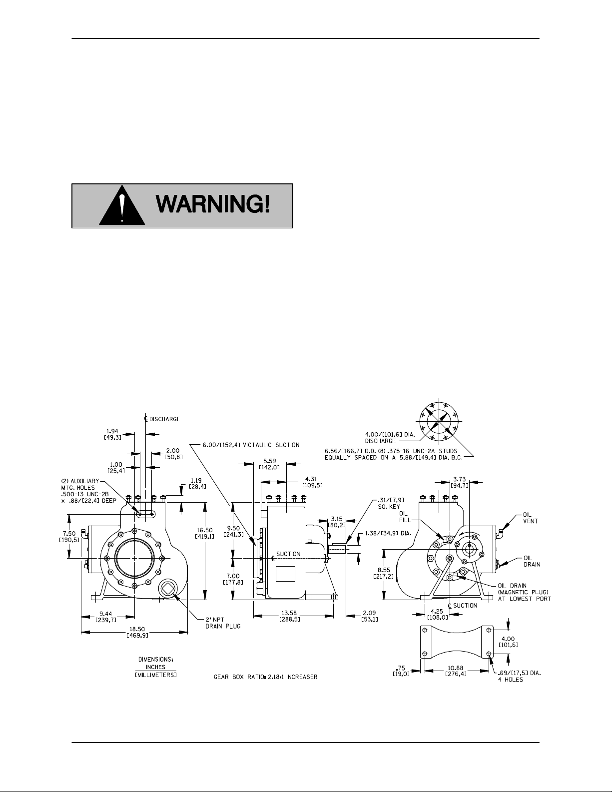
OUTLINE DRAWING
to performance and safety, be sure to limit the in
coming pressure to 50% of the maximum permissi
ble operating pressure as shown on the pump per
formance curve (see Section E, Page 1).
The integral gearbox is designed to be driven
through the vehicle transfer case by a customer‐
supplied universal shaft assembly. The pump cas
ing or gearbox may be rotated in 45_ increments to
assist with alignment with the vehicle tank; howev
er, if the gearbox is to be rotated, some modifica
tions must be made to the gearbox to ensure ade
quate lubrication. Consult the factory for details.
For further assistance, contact your Gorman‐Rupp
distributor or the Gorman‐Rupp Company.
Pump Dimensions
See Figure 1 for the approximate physical dimen
sions of this pump.
Figure 1. Pump Model 06D1-GA
PAGE B - 1INSTALLATION
OM-01256 0 SERIES
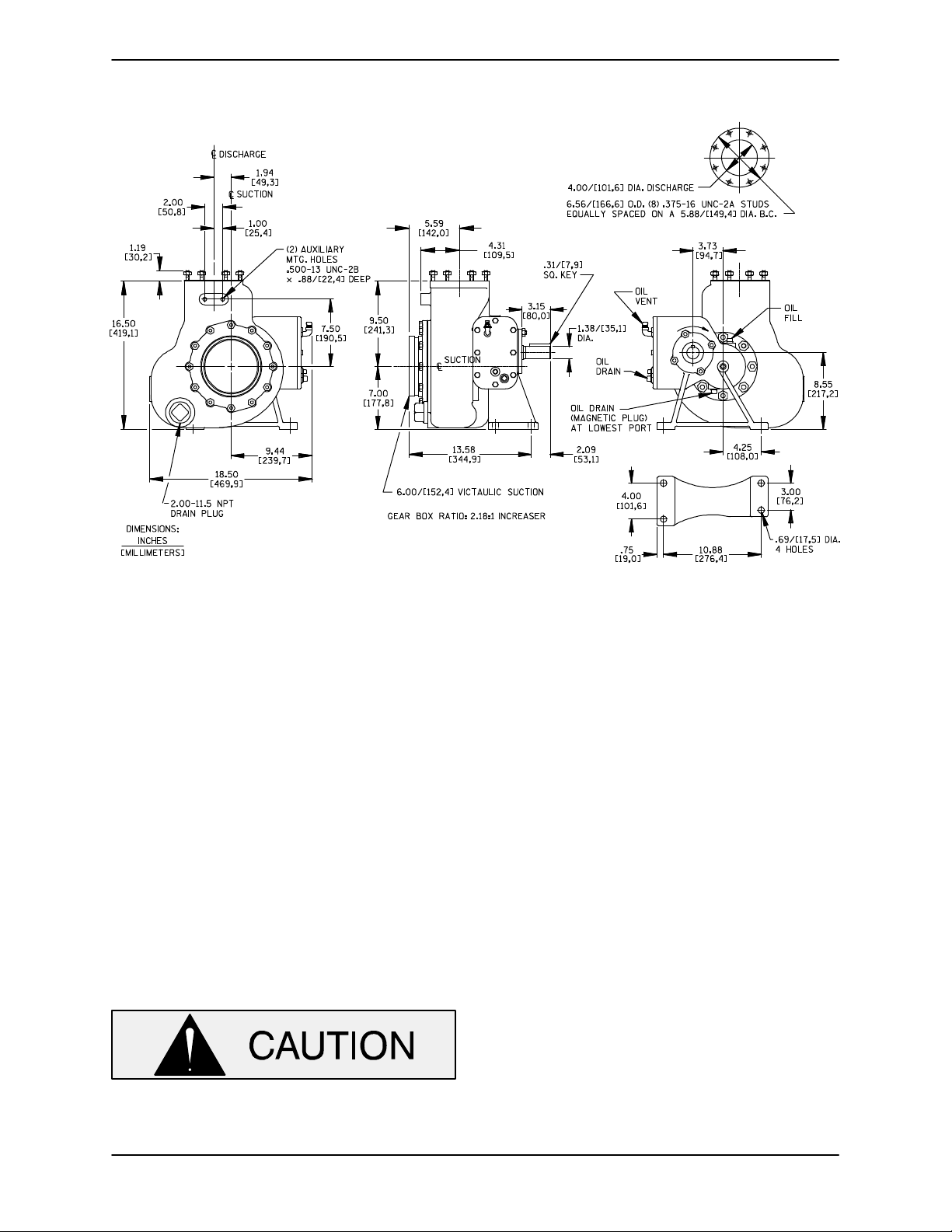
OUTLINE DRAWING
Figure 1. Pump Model 06D1-GAR
PREINSTALLATION INSPECTION
The pump assembly was inspected and tested be
fore shipment from the factory. Before installation,
inspect the pump for damage which may have oc
curred during shipment. Check as follows:
a. Inspect the pump and gearbox for cracks,
dents, damaged threads, and other obvious
damage.
b. Check for and tighten loose attaching hard
ware. Since gaskets tend to shrink after dry
ing, check for loose hardware at mating sur
faces.
c. Carefully read all tags, decals, and markings
on the pump assembly, and perform all duties
indicated.Note the direction of rotation indi
cated on the pump. Check that the pump
shaft rotates in the required direction.
shaft will adversely effect pump perform
ance, and the pump and/or gearbox could
be seriously damaged.
d. Check levels and lubricate as necessary. Re
fer to LUBRICATION in the MAINTENANCE
AND REPAIR section of this manual and per
form duties as instructed.
e. If the pump and gearbox have been stored for
more than 12 months, some of the compo
nents or lubricants may have exceeded their
maximum shelf life. These must be inspected
or replaced to ensure maximum pump serv
ice.
If the maximum shelf life has been exceeded, or if
anything appears to be abnormal, contact your
Gorman‐Rupp distributor or the factory to deter
mine the repair or updating policy. Do not put the
pump into service until appropriate action has
been taken.
VEHICLE REQUIREMENTS
Only operate this pump in the direction in
dicated on the pump body and/or the ac
companying decal. Reverse rotation of the
PAGE B - 2 INSTALLATION
The following instructions apply equally to new in
stallations, rebuilds or retrofits.
OM-012560 SERIES
Tank Preparation
It is essential that any tank scale, dirt, or other for
eign material be removed from the tank and piping
prior to pump installation. Failure to do so could re
sult in clogging or damage to the pump.
Damage to the pump resulting from debris
in the suction line will not be covered by
the pump warranty.
Before connecting the suction and dis
charge piping, carefully check the storage
tank and piping for construction debris
such as nuts, bolts, wire, weld slag, and
other foreign material. Install a commer
cially available 80 mesh screen in the suc
tion line to prevent debris from entering the
pump.
NOTE
If the gearbox is rotated out of the standard position
shown in Figure 1, the oil fill and drain plugs must
be relocated. The magnetic drain plug must be re
located to the lowest port, and the oil vent and el
bow must be relocated to the highest port. Consult
the factory for correct positioning of the fill plug to
provide for proper lubrication of the gearbox.
ALIGNMENT
When installing and/or aligning univer
sal shaft assemblies, switch off the ve
hicle ignition and remove the key to en
sure that the pump will remain inopera
tive.
The alignment of the pump and its power source is
critical for trouble‐free mechanical operation. Be
fore checking alignment, make sure that the gear
box mounting bolts are tight.
POSITIONING PUMP
Lifting
Pump unit weights will vary depending on the
mounting and drive provided. Check the shipping
tag on the unit packaging for the actual weight, and
use lifting equipment with appropriate capacity.
Drain the pump and remove all customer‐installed
equipment such as suction and discharge hoses
or piping before attempting to lift existing, installed
units.
The pump assembly can be seriously
damaged if the cables or chains used to lift
and move the unit are improperly wrapped
around the pump.
Due to the confined mounting location,
specialized equipment such as a transmis
sion jack with custom brackets should be
used to lift and position the pump and
gearbox.
When connecting the universal joint drive shaft as
sembly to a PTO unit, install, support, and align the
drive shaft in accordance with the manufacturer's
instructions. The pump and the drive power source
are generally positioned so that shaft centerlines
are parallel and horizontal. The maximum operat
ing angle should not exceed 15_ (see Figure 2).
Check the direction of rotation of the PTO unit be
fore starting the pump. The drive shaft must rotate
in the direction shown on the body of the pump,
gearbox, and/or decals, tags, and labels.
Do not operate the pump without the
guard in place over the rotating parts.
Exposed rotating parts can catch cloth
ing, fingers, or tools, causing severe in
jury to personnel.
After the power take‐off has been aligned, block
the wheels of the external power source, engage
the braking system, or take other precautions to
ensure that the power source will remain station
ary. Block the wheels on the unit to prevent creep
ing.
PAGE B - 3INSTALLATION
 Loading...