

Gorman-Rupp Pumps 04E1-GHH User Manual
Q
OM−03688−03
August 29, 1995
Rev. C 03-31-10
INSTALLATION, OPERATION,
AND MAINTENANCE MANUAL
WITH PARTS LIST
0 SERIES PUMP
MODEL
04E1−GHH
THE GORMAN-RUPP COMPANY MANSFIELD, OHIO
www.grpumps.com
GORMAN-RUPP OF CANADA LIMITED ST. THOMAS, ONTARIO, CANADA Printed in U.S.A.
1995 The Gorman-Rupp Company

Register your new
Gorman-Rupp pump online at
www.grpumps.com
Valid serial number and e-mail address required.
RECORD YOUR PUMP MODEL AND SERIAL NUMBER
Please record your pump model and serial number in the
spaces provided below. Your Gorman-Rupp distributor
needs this information when you require parts or service.
Pump Model:
Serial Number:

TABLE OF CONTENTS
INTRODUCTION PAGE I − 1. . . . . . . . . . . . . . . . . . . . . . . . . . . . . . . . . . . . . . . . . . . . . . . . .
SAFETY − SECTION A PAGE A − 1. . . . . . . . . . . . . . . . . . . . . . . . . . . . . . . . . . . . . . . . . . .
INSTALLATION − SECTION B PAGE B − 1. . . . . . . . . . . . . . . . . . . . . . . . . . . . . . . . . . . .
PREINSTALLATION INSPECTION PAGE B − 1. . . . . . . . . . . . . . . . . . . . . . . . . . . . . . . . . . . . . . . . . . . .
PUMP INSTALLATION PAGE B − 1. . . . . . . . . . . . . . . . . . . . . . . . . . . . . . . . . . . . . . . . . . . . . . . . . . . . . .
Pump Specifications PAGE B − 1. . . . . . . . . . . . . . . . . . . . . . . . . . . . . . . . . . . . . . . . . . . . . . . . . . . .
Through Torque Capacity PAGE B − 2. . . . . . . . . . . . . . . . . . . . . . . . . . . . . . . . . . . . . . . . . . . . . . .
Pump and Mounting Dimensions PAGE B − 2. . . . . . . . . . . . . . . . . . . . . . . . . . . . . . . . . . . . . . . .
Pump Dimensions PAGE B − 3. . . . . . . . . . . . . . . . . . . . . . . . . . . . . . . . . . . . . . . . . . . . . . . . . . . . .
VEHICLE REQUIREMENTS PAGE B − 4. . . . . . . . . . . . . . . . . . . . . . . . . . . . . . . . . . . . . . . . . . . . . . . . .
Tank Preparation PAGE B − 4. . . . . . . . . . . . . . . . . . . . . . . . . . . . . . . . . . . . . . . . . . . . . . . . . . . . . . .
Vehicle Configuration PAGE B − 4. . . . . . . . . . . . . . . . . . . . . . . . . . . . . . . . . . . . . . . . . . . . . . . . . . .
Brake Installation PAGE B − 4. . . . . . . . . . . . . . . . . . . . . . . . . . . . . . . . . . . . . . . . . . . . . . . . . . . . . .
Air Cylinder Pressure PAGE B − 4. . . . . . . . . . . . . . . . . . . . . . . . . . . . . . . . . . . . . . . . . . . . . . . . . . .
POSITIONING PUMP PAGE B − 4. . . . . . . . . . . . . . . . . . . . . . . . . . . . . . . . . . . . . . . . . . . . . . . . . . . . . . .
Lifting PAGE B − 4. . . . . . . . . . . . . . . . . . . . . . . . . . . . . . . . . . . . . . . . . . . . . . . . . . . . . . . . . . . . . . . . .
Mounting Location PAGE B − 5. . . . . . . . . . . . . . . . . . . . . . . . . . . . . . . . . . . . . . . . . . . . . . . . . . . . .
Mounting Brackets PAGE B − 5. . . . . . . . . . . . . . . . . . . . . . . . . . . . . . . . . . . . . . . . . . . . . . . . . . . . .
Drive Flanges PAGE B − 6. . . . . . . . . . . . . . . . . . . . . . . . . . . . . . . . . . . . . . . . . . . . . . . . . . . . . . . . . .
DRIVE SHAFT AND LINKAGE CONNECTIONS PAGE B − 6. . . . . . . . . . . . . . . . . . . . . . . . . . . . . . . .
Drive Shaft Alignment PAGE B − 6. . . . . . . . . . . . . . . . . . . . . . . . . . . . . . . . . . . . . . . . . . . . . . . . . . .
Gear Shift Connections PAGE B − 7. . . . . . . . . . . . . . . . . . . . . . . . . . . . . . . . . . . . . . . . . . . . . . . . .
SUCTION AND DISCHARGE PIPING PAGE B − 9. . . . . . . . . . . . . . . . . . . . . . . . . . . . . . . . . . . . . . . . .
Typical System Installation PAGE B − 9. . . . . . . . . . . . . . . . . . . . . . . . . . . . . . . . . . . . . . . . . . . . . .
Piping PAGE B − 10. . . . . . . . . . . . . . . . . . . . . . . . . . . . . . . . . . . . . . . . . . . . . . . . . . . . . . . . . . . . . . . .
Valves PAGE B − 10. . . . . . . . . . . . . . . . . . . . . . . . . . . . . . . . . . . . . . . . . . . . . . . . . . . . . . . . . . . . . . . .
Eductors PAGE B − 11. . . . . . . . . . . . . . . . . . . . . . . . . . . . . . . . . . . . . . . . . . . . . . . . . . . . . . . . . . . . . .
OPERATION − SECTION C PAGE C − 1. . . . . . . . . . . . . . . . . . . . . . . . . . . . . . . . . . . . . .
PRIMING PAGE C − 1. . . . . . . . . . . . . . . . . . . . . . . . . . . . . . . . . . . . . . . . . . . . . . . . . . . . . . . . . . . . . . . . .
GROUNDING PAGE C − 1. . . . . . . . . . . . . . . . . . . . . . . . . . . . . . . . . . . . . . . . . . . . . . . . . . . . . . . . . . . . .
STARTING PAGE C − 2. . . . . . . . . . . . . . . . . . . . . . . . . . . . . . . . . . . . . . . . . . . . . . . . . . . . . . . . . . . . . . . .
Rotation PAGE C − 2. . . . . . . . . . . . . . . . . . . . . . . . . . . . . . . . . . . . . . . . . . . . . . . . . . . . . . . . . . . . . .
Drive PAGE C − 2. . . . . . . . . . . . . . . . . . . . . . . . . . . . . . . . . . . . . . . . . . . . . . . . . . . . . . . . . . . . . . . . .
OPERATION PAGE C − 2. . . . . . . . . . . . . . . . . . . . . . . . . . . . . . . . . . . . . . . . . . . . . . . . . . . . . . . . . . . . . .
Operating Controls PAGE C − 2. . . . . . . . . . . . . . . . . . . . . . . . . . . . . . . . . . . . . . . . . . . . . . . . . . . . .
Shifting Sequence PAGE C − 2. . . . . . . . . . . . . . . . . . . . . . . . . . . . . . . . . . . . . . . . . . . . . . . . . . . . .
OPERATING CHECKS PAGE C − 3. . . . . . . . . . . . . . . . . . . . . . . . . . . . . . . . . . . . . . . . . . . . . . . . . . . . . .
Leakage PAGE C − 3. . . . . . . . . . . . . . . . . . . . . . . . . . . . . . . . . . . . . . . . . . . . . . . . . . . . . . . . . . . . . .
Strainer Check PAGE C − 3. . . . . . . . . . . . . . . . . . . . . . . . . . . . . . . . . . . . . . . . . . . . . . . . . . . . . . . . .
Liquid Temperature And Overheating PAGE C − 3. . . . . . . . . . . . . . . . . . . . . . . . . . . . . . . . . . . . .
Pump Vacuum Check PAGE C − 3. . . . . . . . . . . . . . . . . . . . . . . . . . . . . . . . . . . . . . . . . . . . . . . . . .
STOPPING PAGE C − 4. . . . . . . . . . . . . . . . . . . . . . . . . . . . . . . . . . . . . . . . . . . . . . . . . . . . . . . . . . . . . . . .
GEARBOX TEMPERATURE CHECK PAGE C − 4. . . . . . . . . . . . . . . . . . . . . . . . . . . . . . . . . . . . . . . . . .
COLD WEATHER PRESERVATION PAGE C − 4. . . . . . . . . . . . . . . . . . . . . . . . . . . . . . . . . . . . . . . . . . .
i

TABLE OF CONTENTS
(continued)
TROUBLESHOOTING − SECTION D PAGE D − 1. . . . . . . . . . . . . . . . . . . . . . . . . . . . . .
PREVENTIVE MAINTENANCE PAGE D − 2. . . . . . . . . . . . . . . . . . . . . . . . . . . . . . . . . . . . . . . . . . . . . . .
PUMP MAINTENANCE AND REPAIR − SECTION E PAGE E − 1. . . . . . . . . . . . . . . .
PERFORMANCE CURVE PAGE E − 1. . . . . . . . . . . . . . . . . . . . . . . . . . . . . . . . . . . . . . . . . . . . . . . . . . .
PARTS LISTS:
Pump Model PAGE E − 3. . . . . . . . . . . . . . . . . . . . . . . . . . . . . . . . . . . . . . . . . . . . . . . . . . . . . . . . . .
Gearbox Assembly PAGE E − 5 & 7. . . . . . . . . . . . . . . . . . . . . . . . . . . . . . . . . . . . . . . . . . . . . . . . . . . . .
Cross Member Kit PAGE E − 9. . . . . . . . . . . . . . . . . . . . . . . . . . . . . . . . . . . . . . . . . . . . . . . . . . . . . .
PUMP AND SEAL DISASSEMBLY PAGE E − 10. . . . . . . . . . . . . . . . . . . . . . . . . . . . . . . . . . . . . . . . . . . .
Removing Pump and Gearbox PAGE E − 10. . . . . . . . . . . . . . . . . . . . . . . . . . . . . . . . . . . . . . . . . . .
Suction Head and Wear Ring Removal PAGE E − 11. . . . . . . . . . . . . . . . . . . . . . . . . . . . . . . . . . . .
Impeller Removal PAGE E − 11. . . . . . . . . . . . . . . . . . . . . . . . . . . . . . . . . . . . . . . . . . . . . . . . . . . . . .
Seal Removal PAGE E − 11. . . . . . . . . . . . . . . . . . . . . . . . . . . . . . . . . . . . . . . . . . . . . . . . . . . . . . . . . .
Pump Casing Removal PAGE E − 11. . . . . . . . . . . . . . . . . . . . . . . . . . . . . . . . . . . . . . . . . . . . . . . . .
PUMP AND SEAL REASSEMBLY PAGE E − 12. . . . . . . . . . . . . . . . . . . . . . . . . . . . . . . . . . . . . . . . . . . .
Pump Casing Installation PAGE E − 12. . . . . . . . . . . . . . . . . . . . . . . . . . . . . . . . . . . . . . . . . . . . . . . .
Seal Reassembly and Installation PAGE E − 12. . . . . . . . . . . . . . . . . . . . . . . . . . . . . . . . . . . . . . . .
Impeller Installation PAGE E − 14. . . . . . . . . . . . . . . . . . . . . . . . . . . . . . . . . . . . . . . . . . . . . . . . . . . . .
Suction Head and Wear Ring Installation PAGE E − 15. . . . . . . . . . . . . . . . . . . . . . . . . . . . . . . . . .
Installing Pump and Gearbox PAGE E − 15. . . . . . . . . . . . . . . . . . . . . . . . . . . . . . . . . . . . . . . . . . . .
Final Pump Assembly PAGE E − 15. . . . . . . . . . . . . . . . . . . . . . . . . . . . . . . . . . . . . . . . . . . . . . . . . .
GEARBOX DISASSEMBLY PAGE E − 15. . . . . . . . . . . . . . . . . . . . . . . . . . . . . . . . . . . . . . . . . . . . . . . . . .
Air Shift Cover Disassembly PAGE E − 16. . . . . . . . . . . . . . . . . . . . . . . . . . . . . . . . . . . . . . . . . . . . .
Drive Flange Removal PAGE E − 16. . . . . . . . . . . . . . . . . . . . . . . . . . . . . . . . . . . . . . . . . . . . . . . . . .
Output Shaft Disassembly PAGE E − 16. . . . . . . . . . . . . . . . . . . . . . . . . . . . . . . . . . . . . . . . . . . . . . .
Input Shaft Disassembly PAGE E − 16. . . . . . . . . . . . . . . . . . . . . . . . . . . . . . . . . . . . . . . . . . . . . . . .
Idler Shaft Disassembly PAGE E − 17. . . . . . . . . . . . . . . . . . . . . . . . . . . . . . . . . . . . . . . . . . . . . . . . .
Impeller Shaft Disassembly PAGE E − 17. . . . . . . . . . . . . . . . . . . . . . . . . . . . . . . . . . . . . . . . . . . . . .
Cleaning and Inspecting Bearings PAGE E − 17. . . . . . . . . . . . . . . . . . . . . . . . . . . . . . . . . . . . . . .
GEARBOX REASSEMBLY PAGE E − 18. . . . . . . . . . . . . . . . . . . . . . . . . . . . . . . . . . . . . . . . . . . . . . . . . . .
Impeller Shaft Reassembly PAGE E − 18. . . . . . . . . . . . . . . . . . . . . . . . . . . . . . . . . . . . . . . . . . . . . .
Idler Shaft Reassembly PAGE E − 18. . . . . . . . . . . . . . . . . . . . . . . . . . . . . . . . . . . . . . . . . . . . . . . . .
Input Shaft Reassembly PAGE E − 19. . . . . . . . . . . . . . . . . . . . . . . . . . . . . . . . . . . . . . . . . . . . . . . . .
Output Shaft Reassembly PAGE E − 20. . . . . . . . . . . . . . . . . . . . . . . . . . . . . . . . . . . . . . . . . . . . . . .
Air Shift Cover Reassembly PAGE E − 20. . . . . . . . . . . . . . . . . . . . . . . . . . . . . . . . . . . . . . . . . . . . . .
Pressure Testing PAGE E − 20. . . . . . . . . . . . . . . . . . . . . . . . . . . . . . . . . . . . . . . . . . . . . . . . . . . . . . .
Drive Flange Installation PAGE E − 21. . . . . . . . . . . . . . . . . . . . . . . . . . . . . . . . . . . . . . . . . . . . . . . .
LUBRICATION PAGE E − 21. . . . . . . . . . . . . . . . . . . . . . . . . . . . . . . . . . . . . . . . . . . . . . . . . . . . . . . . . . . . .
Seal Assembly PAGE E − 21. . . . . . . . . . . . . . . . . . . . . . . . . . . . . . . . . . . . . . . . . . . . . . . . . . . . . . . . .
Trunnion Bracket PAGE E − 21. . . . . . . . . . . . . . . . . . . . . . . . . . . . . . . . . . . . . . . . . . . . . . . . . . . . . . .
Gearbox Assembly PAGE E − 21. . . . . . . . . . . . . . . . . . . . . . . . . . . . . . . . . . . . . . . . . . . . . . . . . . . . .
− Intermittent (Normal Refueler) Duty Cycle PAGE E − 21. . . . . . . . . . . . . . . . . . . . . . . . . . . . . . .
− Continuous Pumping Duty Cycle PAGE E − 22. . . . . . . . . . . . . . . . . . . . . . . . . . . . . . . . . . . . . .
ii
0 SERIES
OM−03688
INTRODUCTION
Thank You for purchasing a Gorman-Rupp pump.
Read this manual carefully to learn how to safely
install and operate your pump. Failure to do so
could result in personal injury or damage to the
pump.
This pump is an 0 Series, enclosed impeller, centrifugal model, with straight-in suction and without
a suction check valve. It is designed for vehicular
mounting in petroleum service. The basic material
of construction is aluminum, with cast iron wear
rings.
The pump is close-coupled to an integral, 1950
RPM split-shaft gearbox speed increaser with a
2.56:1 ratio. Power is transmitted to the gearbox
through a customer-installed universal shaft assembly.
This manual will alert personnel to known procedures which require special attention, to those
which could damage equipment, and to those
which could be dangerous to personnel. However,
this manual cannot possibly anticipate and provide
detailed precautions for every situation that might
occur during maintenance of the unit. Therefore, it
is the responsibility of the owner/maintenance personnel to ensure that only safe, established main-
tenance procedures are used, and that any procedures not addressed in this manual are performed
only after establishing that neither personal safety
nor pump integrity are compromised by such practices.
Gorman-Rupp of Canada Limited
70 Burwell Road
St. Thomas, Ontario N5P 3R7
Phone: (519) 631−2870
The following are used to alert maintenance personnel to procedures which require special attention, to those which could damage equipment, and
to those which could be dangerous to personnel:
Immediate hazards which WILL result in
severe personal injury or death. These
instructions describe the procedure required and the injury which will result
from failure to follow the procedure.
Hazards or unsafe practices which
COULD result in severe personal injury
or death. These instructions describe
the procedure required and the injury
which could result from failure to follow
the procedure.
For information or technical assistance on the power source, contact the power source manufacturer’s local dealer or representative.
If there are any questions regarding the pump or
its application which are not covered in this manual or in other literature accompanying this unit,
please contact your Gorman-Rupp distributor, or:
The Gorman-Rupp Company
P.O. Box 1217
Mansfield, Ohio 44901−1217
Phone: (419) 755−1011
or:
Hazards or unsafe practices which COULD
result in minor personal injury or product
or property damage. These instructions
describe the requirements and the possible damage which could result from failure
to follow the procedure.
NOTE
Instructions to aid in installation, operation, and
maintenance or which clarify a procedure.
PAGE I − 1INTRODUCTION
0 SERIES OM−03688
SAFETY − SECTION A
This information applies to 0 Series
split-shaft refueler pumps. GormanRupp has no control over or particular
knowledge of the truck chassis which
will be used. Refer to the manual accompanying the truck before attempting to begin operation.
Because pump installations are seldom
identical, this manual cannot possibly
provide detailed instructions and precautions for each specific application.
Therefore, it is the owner/installer’s responsibility to ensure that applications
not addressed in this manual are performed only after establishing that neither operator safety nor pump integrity
are compromised by the installation.
Before attempting to open or service the
pump:
1. Familiarize yourself with this manual.
2. Switch off the vehicle ignition and
remove the key, or take other action to ensure that the pump will remain inoperative.
3. Allow the pump to completely cool
if overheated.
4. Check the temperature before
opening any covers, plates, or
plugs.
5. Close the suction and discharge
valves.
6. Vent the pump slowly and cautiously.
7. Drain the pump.
This pump is designed for vehicular
mounting in petroleum service. Do not
attempt to pump corrosive materials, or
any liquids which may damage the
pump or endanger personnel as a result
of pump failure.
Be certain proper safety practices are
followed before operating or servicing
the pump. Provide adequate ventilation,
prohibit smoking, wear static-resistant
clothing and shoes. Clean up all fuel
spills immediately after occurrence.
Do not operate the pump against a
closed discharge valve for long periods
of time. If operated against a closed discharge valve, pump components will
deteriorate, and the liquid could come
to a boil, build pressure, and cause the
pump casing to rupture or explode.
Overheating may produce dangerous
fumes. Take precautions to ensure the
area surrounding the pump is adequately ventilated. Allow the pump to
cool and use extreme caution when
venting the pump, or when removing
covers, plates, plugs, or fittings.
Do not remove plates, covers, gauges,
pipe plugs, or fittings from an overheated pump. Vapor pressure within the
pump can cause parts being disengaged to be ejected with great force. Allow the pump to cool before servicing.
PAGE A − 1SAFETY

OM−03688
0 SERIES
After the vehicle is positioned for pump
maintenance, block the wheels and set
the emergency brake before attempting
to disconnect the drive shaft or remove
the pump. Be sure the pump is properly
reinstalled and secure before operation.
Never tamper with the governor to gain
more power. The governor establishes
safe operating limits that should not be
exceeded. Limit the maximum input
speed (1950 RPM) and performance as
indicated on the performance curve on
Page E-1.
The gearbox provided on this pump is
designed for operation at a maximum input speed of 1950 RPM. If operated at a
higher RPM, pump or gearbox components may be destroyed.
Decals and tags vital to pump operation
were shipped loose with the pump. Affix
these decals in a prominent place visible to the pump operator.
Never run the pump dry of pumping medium. There must be a supply of liquid to
the pump at all times to prevent destruction
of the shaft seal faces.
This pump has been shipped dry of gearbox lubrication, except for a residual coat-
ing from the testing process of 90 weight
gear oil and Dow Corning Molykote M
Gear Guard" (an anti-wear additive, consisting of molybdenum disulphide solid lubricants suspended in petroleum oil). The
gearbox must be lubricated before the
pump is operated (see LUBRICATION in
Section E).
Decals and tags vital to pump operation
were shipped loose with the pump. Affix
these decals in a prominent place visible to the pump operator.
PAGE A − 2 SAFETY
INSTALLATION − SECTION B
OM−036880 SERIES
Review all SAFETY information in Section A.
Since pump installations are seldom identical, this
section offers only general recommendations and
practices required to inspect, position and arrange
the pump and piping.
Do not test or operate this pump and integral gearbox before reading the installation and operation instructions on
this manual.
This pump is an 0 Series, self-priming centrifugal
model with an integral split-shaft gearbox assembly. The entire unit is designed for midship mounting between the frame members of a petroleum
handling vehicle, where the liquid is supplied to the
pump under pressure. The gearbox replaces a
part of the main drive shaft connecting the transmission to the rear axle.
This design permits full utilization of engine power
to selectively operate either the pump or the rear
driving wheels on the vehicle. Both cannot be op-
erated at the same time.
For further assistance, contact your Gorman-Rupp
distributor or the Gorman-Rupp Company.
PREINSTALLATION INSPECTION
The pump assembly was inspected and tested before shipment from the factory. Before installation,
inspect the pump for damage which may have occurred during shipment. Check as follows:
a. Inspect the pump and gearbox for cracks,
dents, damaged threads, and other obvious
damage.
ing, check for loose hardware at mating surfaces.
c. Carefully read all tags, decals, and markings
on the pump assembly, and perform all duties
indicated. Note the direction of rotation indicated on the pump. Check that the pump
shaft rotates in the required direction.
Only operate this pump in the direction indicated on the gearbox and/or the accompanying decal. Reverse rotation of the
shaft will adversely effect pump performance, and the pump and/or gearbox could
be seriously damaged.
d. The gearbox assembly was shipped dry of
lubricant. Refer to LUBRICATION in the
MAINTENANCE AND REPAIR section of this
manual and perform duties as instructed.
e. If the pump and gearbox have been stored for
more than 12 months, some of the components or lubricants may have exceeded their
maximum shelf life. These must be inspected
or replaced to ensure maximum pump service.
If the maximum shelf life has been exceeded, or if
anything appears to be abnormal, contact your
Gorman-Rupp distributor or the factory to determine the repair or updating policy. Do not put the
pump into service until appropriate action has
been taken.
PUMP INSTALLATION
Pump Specifications
b. Check for and tighten loose attaching hard-
ware. Since gaskets tend to shrink after dry-
See Table 1 for the typical pump specifications and
gearbox data.
PAGE B − 1INSTALLATION

OM−03688 0 SERIES
Table 1. Pump Specifications
Pump Type Self-priming, centrifugal with enclosed impeller. . . . . . . . . . . . . . . . . . . . . . . . . . . . . . . .
Suction 4-inch Victaulic" fitting. . . . . . . . . . . . . . . . . . . . . . . . . . . . . . . . . . . . . . . . . . . . . . . . . . . . .
Discharge 4-inch Victaulic" fitting. . . . . . . . . . . . . . . . . . . . . . . . . . . . . . . . . . . . . . . . . . . . . . . . . .
Nominal Capacity See the Performance Curve, Page E-1. . . . . . . . . . . . . . . . . . . . . . . . . . . . . .
Impeller Shaft Seal Mechanical self-lubricated. . . . . . . . . . . . . . . . . . . . . . . . . . . . . . . . . . . . . . . .
Gearbox (Air Shift)
Air Pressure Required at Shift Cylinder 70-140 psi (5,1-10,2 kg/cm) through 1/4" line. . . .
Gear Ratio 2.56:1 Speed Increase. . . . . . . . . . . . . . . . . . . . . . . . . . . . . . . . . . . . . . . . . . . . . . . . . .
Input shaft Rotation Clockwise (when viewed from the trunnion end). . . . . . . . . . . . . . . . . . . .
Maximum Input Speed 1950 RPM (See the Performance Curve, Page E-1). . . . . . . . . . . . . .
Input & Output Shaft Heavy-duty 2-3/4 inch - 10 spline. . . . . . . . . . . . . . . . . . . . . . . . . . . . . . . .
Input & Output Flanges Dana" Heavy-Duty 1800 Series. . . . . . . . . . . . . . . . . . . . . . . . . . . . . . .
Lubrication 68 U.S. ounces (2011 ml) - See LUBRICATION, Section E for SAE grade. . . . .
6 fl. oz. (18 ml) ‘Molykote M Gear Guard’ (Dow Corning)
Approx. Net Weight (pump and gearbox) 285 pounds (129,3 kg). . . . . . . . . . . . . . . . . . . . . . . . . . .
Table 2. Through Torque Capacity Based On Shaft and Spline Size
Type of Engine Transmission Max Through Torque (ft.-lbs.)
Diesel Automatic 11,000
Manual 10,000
Gasoline Automatic 13,300
Manual 12,300
Pump and Mounting Dimensions
A 40 inch (1016 mm) cross member is provided for
mounting the output end of the gearbox, and a
trunnion mount is provided for the input end. This
design provides a flexible three-point suspension.
The trunnion mount prevents the chassis frame
twist from being transmitted through the gearbox.
See Figure 1 on page B−3 and Figure 2 on page
E−4 for the physical dimensions of the pump.
PAGE B − 2 INSTALLATION
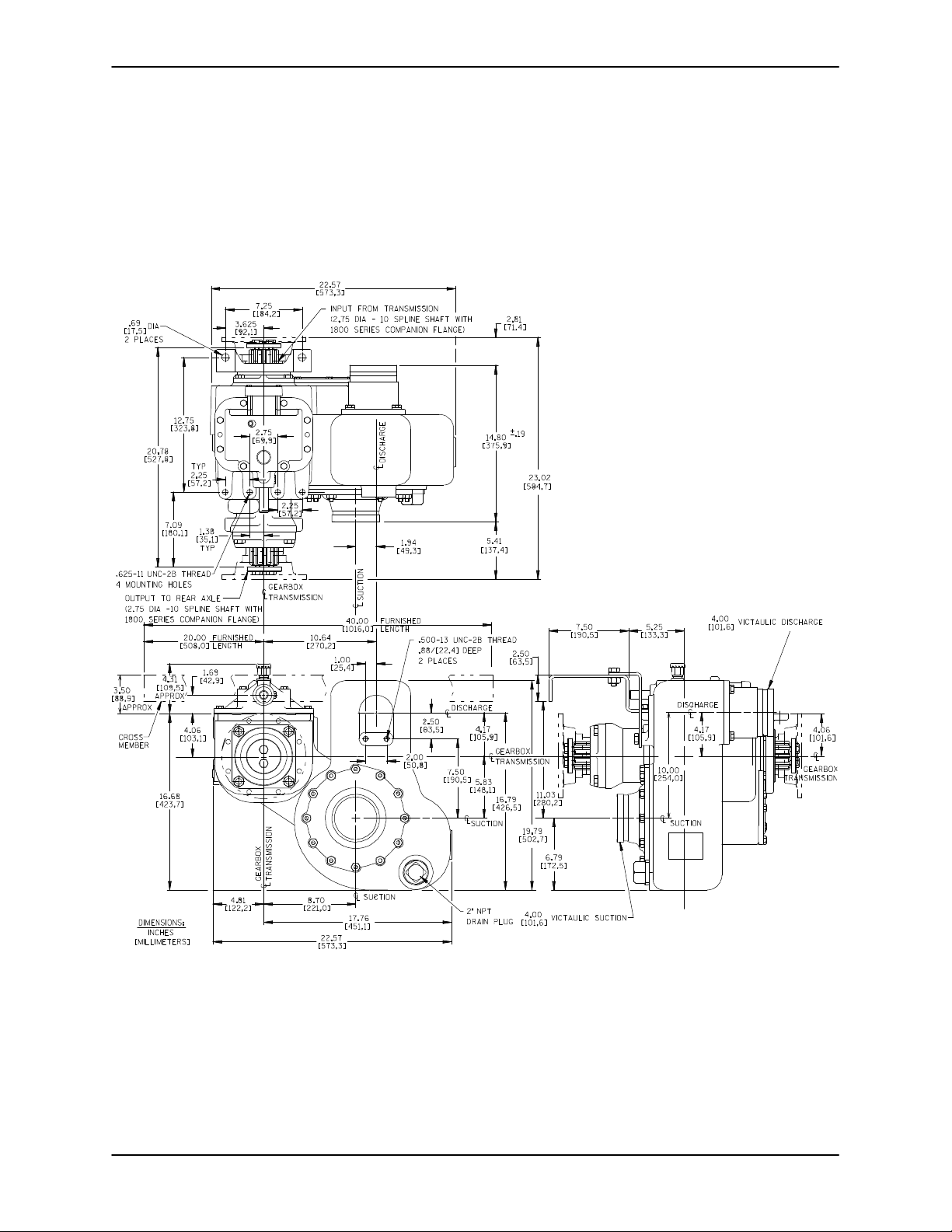
DIMENSIONAL DRAWING
OM−036880 SERIES
Figure 1. Pump Model 04E1-GHH Dimensions
PAGE B − 3INSTALLATION
OM−03688 0 SERIES
VEHICLE REQUIREMENTS
The following instructions apply equally to new installations, rebuilds or retrofits.
After installation, do not attempt to test run
or operate the pump and integral gearbox
before reading OPERATION, Section B.
The gearbox was shipped dry of lubrication, except for a residual coating from the
testing process of Dow Corning
‘Molykote M Gear Guard’ (an anti-wear
additive, consisting of molybdenum disulphide solid lubricants suspended in petroleum oil). Lubricate the gearbox as instructed in LUBRICATION, Section E be-
fore attempting to operate the pump.
Tank Preparation
It is essential that any tank scale, dirt, or other foreign material be removed from the tank and piping
prior to pump installation. Failure to do so could result in clogging or damage to the pump.
low installation of the gearbox at the proper angle,
ant that jumper hoses are long enough to allow a
full turning radius.
Brake Installation
When shifting from vehicle drive to pump
mode, or vice versa, input shaft rotation
must be limited to no less than 2 RPM or
no more than 15 RPM at the time of the
shift. Stopping the input shaft entirely may
cause a butt-shift" condition, which will
prevent the shift from occurring. Shaft rotation in excess of 15 RPM causes raking of
the gears. Either of these conditions can
damage gears, resulting in premature
gearbox failure.
Vehicles with automatic transmissions should be
equipped with a brake on the transmission shaft to
slow, but not stop, shaft rotation during shifting.
Air Cylinder Pressure
For proper operation of the gearbox, the air shift
device requires air pressure of 70 to 140 psi (482 to
965 kPa). See Gear Shift Connections for further
information.
POSITIONING PUMP
Damage to the pump resulting from debris
in the suction line will not be covered by
Lifting
the pump warranty.
Pump unit weights will vary depending on the
Before connecting the suction and discharge piping, carefully check the storage
tank and piping for construction debris
such as nuts, bolts, wire, weld slag, and
other foreign material. Install a commercially available 80 mesh screen in the suction line to prevent debris from entering the
mounting and drive provided. Check the shipping
tag on the unit packaging for the actual weight, and
use lifting equipment with appropriate capacity.
Drain the pump and remove all customer-installed
equipment such as suction and discharge hoses
or piping before attempting to lift existing, installed
units.
pump.
Vehicle Configuration
If the pump is to be used in tractor-trailer or
straight-truck plus trailer service, either a liquid fifth
wheel or jumper hoses are required. Be sure the
drive line of the tractor-trailer is long enough to al-
PAGE B − 4 INSTALLATION
The pump assembly can be seriously
damaged if the cables or chains used to lift
and move the unit are improperly wrapped
around the pump.
OM−036880 SERIES
Due to the confined mounting location,
specialized equipment such as a transmission jack with custom brackets should be
used to lift and position the pump and
gearbox.
Mounting Location
The following factors must be considered when selecting a mounting location for the pump.
a. Mounting brackets
b. Universal joint angles
c. Shift linkage
d. Piping
e. Ground clearance
f. Accessibility of pump and gearbox for service..
Any damage to the pump or gearbox resulting from
improper mounting and installation is not covered
by the Gorman-Rupp Warranty.
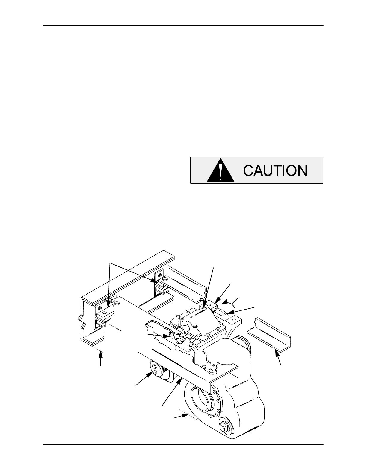
Mounting Brackets
The customer must furnish two cross members
which fit between the vehicle chassis side rails (see
Figure 2). They must be heavy enough to support
the weight of the pump assembly and provide easy
access for pump maintenance.
Secure the rear cross member rigidly to the pump
and gearbox using a fabricated mounting bracket
(customer-furnished). The mounting bracket must
fasten to the threaded holes located in the pump
casing above the pump suction, and in the top of
the gearbox housing. The bracket and cross member must not obstruct pump operation or impede
removal of the pump casing during maintenance.
The rear cross member or mounting
bracket must not interfere with movement
of the air shift indicator shaft (located on
top of the gearbox). If necessary, drill a
1-inch (25,4 mm) diameter hole through
the cross member or bracket to provide
clearance.
RUBBER MOUNTED
BY CUSTOMER
1" [25,4 mm] DIA.
HOLE FOR AIR
SHIFT POSITION
INDICATOR SHAFT
29" * [736,6 mm] APPROX.
ROAD CLEARANCE
OUTPUT TO REAR AXLE
(SHOWN WITHOUT FLANGES)
REAR CROSS MEMBER
(SUPPLIED BY CUSTOMER)
16.31"* [414,3 mm] APPROX.
ROAD CLEARANCE
NOTE: DIMENSIONS MARKED WITH AN ASTERISK (*) MAY BE
ALTERED TO FACILITATE INSTALLATION OF UNIT
AIR SHIFT COVER
TRUNNION BRACKET
INPUT ROTATION FOR PUMP
DRIVE INPUT FROM
TRANSMISSION
FRONT CROSS MEMBER
(SUPPLIED BY CUSTOMER)
Figure 2. Typical Pump Mounting on Vehicle Chassis
PAGE B − 5INSTALLATION
OM−03688 0 SERIES
The drive input end of the gearbox is fitted with a
trunnion which prevents chassis frame twist from
being transmitted through the gearbox. Mount the
trunnion to the front cross member (not supplied)
to support the drive input end of the pump. When
mounting the trunnion, make certain that it will not
interfere with the input drive flange. The trunnion
mounting foot must be directed toward the input
flange.
Position the cross members and mounted pump
on the side rails of the chassis. The cross members
must be mounted with rubber or other vibrationdampening material when secured to the side
rails.
Do not secure the cross members to the side rails
before establishing the exact location and position
of the air shift rod and shift indicator connections.
Be careful not to put the pump in a bind from front
to rear during mounting. Improper alignment could
result in bearing or gear failure, or gearbox breakage (see Drive Shaft Alignment).
DRIVE SHAFT AND
LINKAGE CONNECTIONS
Drive Shaft Alignment
To promote maximum universal joint and bearing
life, the universal joint angles must be kept to a
minimum. A joint angle of 1 is required for proper
needle bearing circulation, but excessive angles
cause accelerated wear and require a lower maximum operating speed (see Table 3).
Table 3. Joint Angle/Maximum RPM
JOINT
ANGLE
5 5000 RPM
6, 30’ 4000 RPM
8 3000 RPM
Align the gearbox with the transmission and the
rear axle to obtain the optimum universal joint
angles. See Figure 3 for drive shaft alignment.
MAXIMUM
SPEED
Drive Flanges
The input and output shafts on the gearbox (2-3/4
inch, 10-spline) are equipped with heavy-duty
Dana 1800 Series flanges. The shaft splines are
designed to produce a tight interference fit with the
drive flange. This fit is intentional to eliminate fretting corrosion.
For instructions on installing or removing drive
flanges and universal joints, see the specific areas
in MAINTENANCE AND REPAIR, Section E.
Be certain the rear axle position when the
vehicle is empty or fully loaded will not
cause excessive universal joint angles, or
cause the drive shaft slip joints to bottom
out.
When installing and/or aligning universal shaft assemblies, shut off the vehicle ignition and remove the key to ensure that the pump will remain inoperative.
PAGE B − 6 INSTALLATION
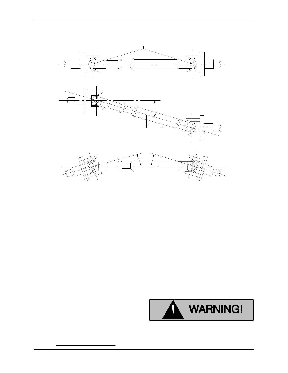
LUGS MUST BE IN LINE, REGARDLESS
OF OPERATING ANGLE SHOWN BELOW
LUG ALIGNMENT
SHAFTS PARALLEL, ANGLES EQUAL
OM−036880 SERIES
SHAFTS NOT PARALLEL, ANGLES EQUAL
Figure 3. Drive Shaft Alignment
The alignment of the pump and its power source is
critical for trouble-free mechanical operation. Before checking alignment, make sure that the gearbox mounting bolts are tight.
When connecting the universal joint drive shaft assembly to a PTO unit, install, support, and align the
drive shaft in accordance with the manufacturer’s
instructions. The pump and the drive power source
are generally positioned so that shaft centerlines
are parallel and horizontal.
Make sure the horizontal and vertical joints are
equal. Limit the angles to 1 to 3 using a short
coupled joint, and less than 8 with a double joint
assembly. The maximum operating angle should
not exceed 15 (see Figure 3).
NOTE
Install a short coupled slip joint on the input side
and a double joint with slip on the output side of the
gearbox to attain the prescribed angles and eliminate tensile stress on the shaft.
The input and output shafts should be completely
subassembled and checked for straightness and
balance before installation. Also check the universal joint yokes for proper alignment.
Check the direction of rotation of the PTO unit before starting the pump. The drive shaft must rotate
in the direction shown on the body of the pump,
gearbox, and/or decals, tags, and labels.
Gear Shift Connections
After the pump is mounted to the chassis, hook up
the air shift rod to the proper control stations.
Decals and tags vital to pump operation
were shipped loose with the pump.
These decals must be affixed in a prominent place visible to the pump operator.
PAGE B − 7INSTALLATION
OM−03688 0 SERIES
Proper operation of the gearbox air shift requires
air pressure of 70 to 140 psi (5,1 to 10,2 kg/cm)
and 1/4" air lines. The air line connection at the end
cap of the air cylinder is for vehicle operation, and
the air line connection at the top of the air shifter
cover is for pump operation. Seal all hose fittings
with Permatex" or equivalent compound.
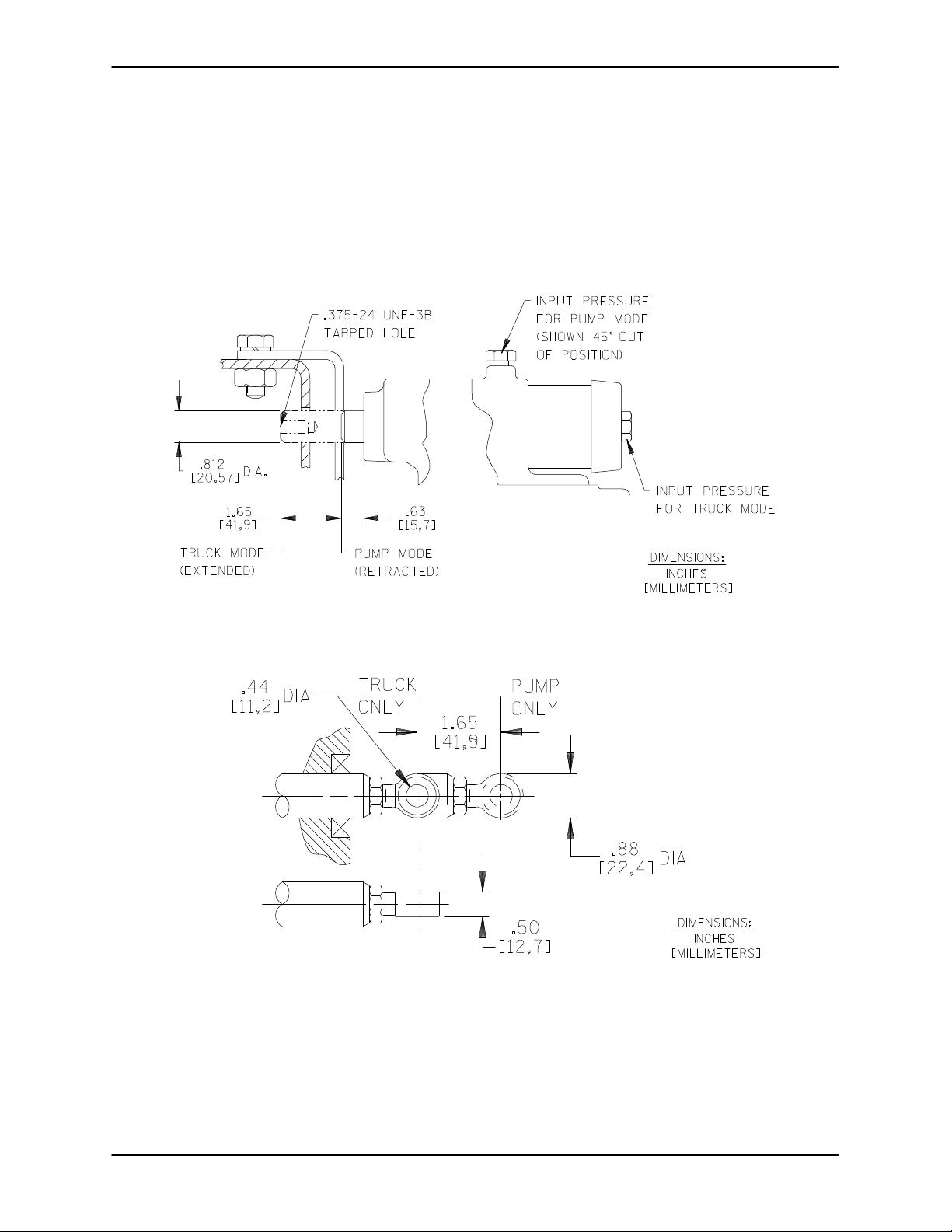
When activated, the shifter rod travels through a
hole in the rear cross member. A customer-
supplied shift indicator (mechanical, electrical, or
air operated device) should be installed in this area
to indicate shifter mode to the pump operator. A
tapped hole is provided in the shaft for convenience.
See Figures 4 and 5 for the approximate shaft travel and hole size. See Figure 4, Section E for Air Shift
Kit parts.
Figure 4. Air Shifter Shaft Detail
Figure 5. Optional Manual Shifter
SUCTION AND DISCHARGE PIPING
Typical System Installation
system utilizing flow-directing (FDF) valves, eductors, related piping and safety accessories. Some
of the accessories are available from GormanRupp as optional equipment.
Most petroleum handling vehicles perform both
fueling and defueling operations. This requires a
PAGE B − 8 INSTALLATION
Refer to Figures 6 and 7 for illustrations of typical
piping systems used on refueling vehicles.
 Loading...