

Gorman-Rupp Pumps 04C3-B User Manual
BCE
OM‐01218‐03
May 26, 1981
Rev. C 8‐12‐2013
INSTALLATION, OPERATION,
AND MAINTENANCE MANUAL
WITH PARTS LIST
0 SERIES PUMP
MODEL
04C3-B
THE GORMAN‐RUPP COMPANY MANSFIELD, OHIO
www.grpumps.com
GORMAN‐RUPP OF CANADA LIMITED ST. THOMAS, ONTARIO, CANADA Printed in U.S.A.
2009 The Gorman‐Rupp Company

Register your new
Gorman‐Rupp pump online at
www.grpumps.com
Valid serial number and e‐mail address required.
RECORD YOUR PUMP MODEL AND SERIAL NUMBER
Please record your pump model and serial number in the
spaces provided below. Your Gorman‐Rupp distributor
needs this information when you require parts or service.
Pump Model:
Serial Number:

TABLE OF CONTENTS
INTRODUCTION PAGE I - 1.................................................
SAFETY ‐ SECTION A PAGE A - 1............................................
INSTALLATION - SECTION B PAGE B - 1....................................
Pump Dimensions PAGE B - 1.....................................................
PREINSTALLATION INSPECTION PAGE B - 2............................................
POSITIONING PUMP PAGE B - 2.......................................................
Lifting PAGE B - 2.................................................................
Mounting PAGE B - 2.............................................................
SUCTION AND DISCHARGE PIPING PAGE B - 2.........................................
Materials PAGE B - 2..............................................................
Line Configuration PAGE B - 3......................................................
Connections to Pump PAGE B - 3..................................................
Gauges PAGE B - 3...............................................................
SUCTION LINES PAGE B - 3...........................................................
Fittings PAGE B - 3...............................................................
Strainers PAGE B - 3..............................................................
Sealing PAGE B - 3...............................................................
Suction Lines in Sumps PAGE B - 3.................................................
Suction Line Positioning PAGE B - 4................................................
DISCHARGE LINES PAGE B - 4........................................................
Siphoning PAGE B - 4.............................................................
Valves PAGE B - 4................................................................
Bypass Lines PAGE B - 4..........................................................
ALIGNMENT PAGE B - 5..............................................................
Coupled Drives PAGE B - 5........................................................
Drive Belts PAGE B - 6............................................................
DRIVE BELT TENSIONING PAGE B - 6..................................................
General Rules of Tensioning PAGE B - 6.............................................
OPERATION - SECTION C PAGE C - 1......................................
PRIMING PAGE C - 1.................................................................
STARTING PAGE C - 1................................................................
Rotation PAGE C - 1..............................................................
OPERATION PAGE C - 2..............................................................
Lines With a Bypass PAGE C - 2....................................................
Lines Without a Bypass PAGE C - 2.................................................
Leakage PAGE C - 2..............................................................
Liquid Temperature And Overheating PAGE C - 2.....................................
Strainer Check PAGE C - 2.........................................................
Pump Vacuum Check PAGE C - 3..................................................
STOPPING PAGE C - 3................................................................
Cold Weather Preservation PAGE C - 3..............................................
BEARING TEMPERATURE CHECK PAGE C - 3..........................................
TROUBLESHOOTING - SECTION D PAGE D - 1..............................
PREVENTIVE MAINTENANCE PAGE D - 3...............................................
i

TABLE OF CONTENTS
(continued)
PUMP MAINTENANCE AND REPAIR ‐ SECTION E PAGE E - 1.................
STANDARD PERFORMANCE CURVE PAGE E - 1........................................
PARTS LISTS:
Pump End Assembly PAGE E - 3...................................................
PUMP AND SEAL DISASSEMBLY AND REASSEMBLY PAGE E - 4.........................
Pump Disassembly PAGE E - 4.....................................................
Impeller Removal PAGE E - 5......................................................
Seal Removal and Disassembly PAGE E - 5..........................................
Shaft and Bearing Removal and Disassembly PAGE E - 5.............................
Shaft and Bearing Reassembly and Installation PAGE E - 6............................
Seal Reassembly and Installation PAGE E - 7........................................
Impeller Installation PAGE E - 9.....................................................
Pump Reassembly PAGE E - 9.....................................................
Final Pump Assembly PAGE E - 10..................................................
LUBRICATION PAGE E - 10.............................................................
Seal Assembly PAGE E - 10.........................................................
Bearing PAGE E - 10...............................................................
ii
0 SERIES
OM-01218
INTRODUCTION
Thank You for purchasing a Gorman‐Rupp pump.
Read this manual carefully to learn how to safely
install and operate your pump. Failure to do so
could result in personal injury or damage to the
pump.
This Installation, Operation, and Maintenance
manual is designed to help you achieve the best
performance and longest life from your Gorman‐
Rupp pump.
This pump is an 0 Series, enclosed impeller, self‐
priming centrifugal model, designed with straight
in suction, without a suction check valve. It is de
signed to handle clear liquids containing specified
entrained solids. The basic material of construc
tion for wetted parts is gray iron, with bronze impel
ler and steel shaft.
If there are any questions regarding the pump or
its application which are not covered in this man
ual or in other literature accompanying this unit,
please contact your Gorman‐Rupp distributor, or:
The Gorman‐Rupp Company
P.O. Box 1217
Mansfield, Ohio 44901-1217
Phone: (419) 755-1011
or:
Gorman‐Rupp of Canada Limited
70 Burwell Road
St. Thomas, Ontario N5P 3R7
Phone: (519) 631-2870
Because pump installations are seldom identical,
this manual cannot possibly provide detailed in
structions and precautions for every aspect of
each specific application. Therefore, it is the re
sponsibility of the owner/installer of the pump to
ensure that applications not addressed in this
manual are performed only after establishing that
neither operator safety nor pump integrity are com
promised by the installation. Pumps and related
equipment must be installed and operated ac
cording to all national, local and industry stan
dards.
The following are used to alert maintenance per
sonnel to procedures which require special atten
tion, to those which could damage equipment, and
to those which could be dangerous to personnel:
Immediate hazards which WILL result in
severe personal injury or death. These
instructions describe the procedure re
quired and the injury which will result
from failure to follow the procedure.
Hazards or unsafe practices which
COULD result in severe personal injury
or death. These instructions describe
the procedure required and the injury
which could result from failure to follow
the procedure.
Hazards or unsafe practices which COULD
result in minor personal injury or product
or property damage. These instructions
describe the requirements and the possi
ble damage which could result from failure
to follow the procedure.
NOTE
Instructions to aid in installation, operation,and
maintenance, or which clarify a procedure.
PAGE I - 1INTRODUCTION
0 SERIES
SAFETY ‐ SECTION A
This information applies to 0 Series ba
sic pumps. Gorman‐Rupp has no con
trol over or particular knowledge of the
power source which will be used. Refer
to the manual accompanying the power
source before attempting to begin oper
ation.
This manual will alert personnel to
known procedures which require spe
cial attention, to those which could
damage equipment, and to those which
could be dangerous to personnel. How
ever, this manual cannot possibly antici
pate and provide detailed instructions
and precautions for every situation that
might occur during maintenance of the
unit. Therefore, it is the responsibility of
the owner/maintenance personnel to
ensure that only safe, established main
tenance procedures are used, and that
any procedures not addressed in this
manual are performed only after estab
lishing that neither personal safety nor
pump integrity are compromised by
such practices.
OM-01218
This pump is designed to handle petro
leum products or other clean liquids
that do not contain large entrained sol
ids. Do not attempt to pump liquids
which may damage the pump or endan
ger personnel as a result of pump fail
ure.
This pump is designed to handle petro
leum products or other clean liquids
that do not contain large entrained sol
ids. If the pump is used for handling vol
atile, flammable liquids, all drivers and/
or controls must meet industry stan
dards and codes for use in an explosive
atmosphere. Do not attempt to pump liq
uids for which the pump, driver and/or
controls have not been approved, or
which may damage the pump or endan
ger personnel as a result of pump fail
ure.
Before attempting to open or service the
pump:
1. Familiarize yourself with this man
ual.
2. Disconnect or lock out the power
source to ensure that the pump will
remain inoperative.
3. Allow the pump to completely cool
if overheated.
4. Check the temperature before
opening any covers, plates, or
plugs.
5. Close the suction and discharge
valves.
6. Vent the pump slowly and cau
tiously.
7. Drain the pump.
If this pump is used for volatile and/or
flammable liquids, be certain proper
safety practices are followed before op
erating or servicing the pump. Provide
adequate ventilation, prohibit smoking,
wear static‐resistant clothing and
shoes. Clean up all fuel spills immedi
ately after occurrence.
Do not install and operate a non‐explo
sion proof motor in an explosive atmo
sphere. Install, connect, and operate
the motor in accordance with the Na
PAGE A - 1SAFETY
tional Electric Code and all local codes.
If there is a conflict between the instruc
tions in the manual accompanying the
unit and the National Electric Code or
the applicable local code, the National
or local code shall take precedence.
If this pump is used with volatile and/or
flammable liquids, overheating may
produce dangerous fumes. Take pre
cautions to ensure the area surrounding
the pump is adequately ventilated. Al
low the pump to cool and use extreme
caution when venting the pump, or
when removing covers, plates, plugs, or
fittings.
0 SERIESOM-01218
Do not operate the pump without the
shields and/or guards in place over the
drive shaft, belts, and/or couplings, or
other rotating parts. Exposed rotating
parts can catch clothing, fingers, or
tools, causing severe injury to person
nel.
Do not operate the pump against a
closed discharge valve for long periods
of time. If operated against a closed dis
charge valve, pump components will
deteriorate, and the liquid could come
to a boil, build pressure, and cause the
pump casing to rupture or explode.
Death or serious personal injury and
damage to the pump or components
can occur if proper lifting procedures
are not observed. Make certain that
hoists, chains, slings or cables are in
good working condition and of suffi
cient capacity and that they are posi
tioned so that loads will be balanced
and the pump or components will not be
damaged when lifting. Suction and dis
charge hoses and piping must be re
moved from the pump before lifting. Lift
the pump or component only as high as
necessary and keep personnel away
from suspended objects.
After the pump has been installed, make
certain that the pump and all piping or
hose connections are tight, properly
supported and secure before operation.
Overheated pumps can cause severe
burns and injuries. If overheating of the
pump occurs:
1. Stop the pump immediately.
2. Ventilate the area.
3. Allow the pump to completely cool.
4. Check the temperature before
opening any covers, plates,
gauges, or plugs.
5. Vent the pump slowly and cau
tiously.
6. Refer to instructions in this manual
before restarting the pump.
Do not remove plates, covers, gauges,
pipe plugs, or fittings from an over
heated pump. Vapor pressure within the
pump can cause parts being disen
gaged to be ejected with great force. Al
low the pump to cool before servicing.
PAGE A - 2 SAFETY

0 SERIES
OM-01218
Never run this pump backwards. Be cer
tain that rotation is correct before fully
engaging the pump.
Pumps and related equipment must be in
stalled and operated according to all na
tional, local and industry standards.
PAGE A - 3SAFETY
0 SERIES OM-01218
INSTALLATION - SECTION B
Review all SAFETY information in Section A.
Since pump installations are seldom identical, this
section offers only general recommendations and
practices required to inspect, position, and ar
range the pump and piping.
Most of the information pertains to a standard
static lift application where the pump is positioned
above the free level of liquid to be pumped.
If installed in a flooded suction application where
the liquid is supplied to the pump under pressure,
some of the information such as mounting, line
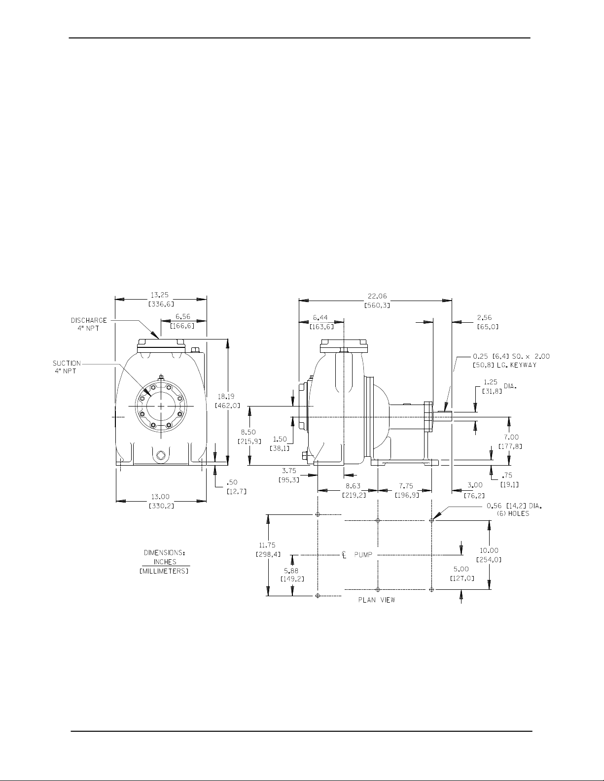
OUTLINE DRAWING
configuration, and priming must be tailored to the
specific application. Since the pressure supplied
to the pump is critical to performance and safety,
be sure to limit the incoming pressure to 50% of the
maximum permissible operating pressure as
shown on the pump performance curve.
For further assistance, contact your Gorman‐Rupp
distributor or the Gorman‐Rupp Company.
Pump Dimensions
See Figure 1 for the approximate physical dimen
sions of this pump.
Figure 1. Pump Model 04C3-B
PAGE B - 1INSTALLATION
OM-01218 0 SERIES
PREINSTALLATION INSPECTION
The pump assembly was inspected and tested be
fore shipment from the factory. Before installation,
inspect the pump for damage which may have oc
curred during shipment. Check as follows:
a. Inspect the pump and engine for cracks,
dents, damaged threads, and other obvious
damage.
b. Check for and tighten loose attaching hard
ware. Since gaskets tend to shrink after dry
ing, check for loose hardware at mating sur
faces.
c. Carefully read all tags, decals, and markings
on the pump assembly, and perform all duties
indicated.
POSITIONING PUMP
Death or serious personal injury and
damage to the pump or components
can occur if proper lifting procedures
are not observed. Make certain that
hoists, chains, slings or cables are in
good working condition and of suffi
cient capacity and that they are posi
tioned so that loads will be balanced
and the pump or components will not be
damaged when lifting. Suction and dis
charge hoses and piping must be re
moved from the pump before lifting. Lift
the pump or component only as high as
necessary and keep personnel away
from suspended objects.
Lifting
Only operate this pump in the direction in
dicated by the arrow on the pump body
and on the accompanying decal. Refer to
ROTATION in OPERATION, Section C.
d. Check levels and lubricate as necessary. Re
fer to LUBRICATION in the MAINTENANCE
AND REPAIR section of this manual and per
form duties as instructed.
e. If the pump and power source have been
stored for more than 12 months, some of the
components or lubricants may have ex
ceeded their maximum shelf life. These must
be inspected or replaced to ensure maxi
mum pump service.
If the maximum shelf life has been exceeded, or if
anything appears to be abnormal, contact your
Gorman‐Rupp distributor or the factory to deter
mine the repair or updating policy. Do not put the
pump into service until appropriate action has
been taken.
Pump unit weights will vary depending on the
mounting and drive provided. Check the shipping
tag on the unit packaging for the actual weight, and
use lifting equipment with appropriate capacity.
Drain the pump and remove all customer‐installed
equipment such as suction and discharge hoses
or piping before attempting to lift existing, installed
units.
The pump assembly can be seriously
damaged if the cables or chains used to lift
and move the unit are improperly wrapped
around the pump.
Mounting
Locate the pump in an accessible place as close as
practical to the liquid being pumped. Level mount
ing is essential for proper operation.
The pump may have to be supported or shimmed
to provide for level operation or to eliminate vibra
tion.
SUCTION AND DISCHARGE PIPING
Pump performance is adversely effected by in
creased suction lift, discharge elevation, and fric
PAGE B - 2 INSTALLATION
 Loading...