

Page 1
ACE
OM---01216---OE08
March 18, 2002
INSTALLATION, OPERATION,
AND MAINTENANCE MANUAL
WITH PARTS LIST
0SERIESPUMP
MODEL
04B3---F4L
THE GORMAN-RUPP COMPANY D MANSFIELD, OHIO
GORMAN-RUPP OF CANADA LIMITED D ST.THOMAS, ONTARIO, CANADA Printed in U.S.A.
ECopyright by the Gorman-Rupp Company
Page 2

The engine exhaust from this
product contains chemicals
known to the State ofCaliforniato
cause cancer, birth defects or
other reproductive harm.
Page 3

TABLE OF CONTENTS
INTRODUCTION PAGE I --- 1.................................................
SAFETY - SECTION A PAGE A --- 1............................................
IN S TA LLATIO N --- SE C TION B PA G E B --- 1....................................
Pump Dimensions PAGE B --- 1.....................................................
PREINSTALLATION INSPECTION PAGE B --- 1............................................
Battery Specifications And Installation PAGE B --- 2....................................
POSITIONING PUMP PA GE B --- 2.......................................................
Lifting PA GE B --- 2.................................................................
Alignment PA GE B --- 2.............................................................
Mounting PA GE B --- 2.............................................................
SUCTION AND DISCHARGE PIPING PAGE B --- 3.........................................
Materials PA GE B --- 3..............................................................
Line Configuration PAGE B --- 3......................................................
Connections to Pump PAGE B --- 3..................................................
Gauges PA GE B --- 3...............................................................
SUCTION LINES PAGE B --- 3...........................................................
Fittings PA GE B --- 3...............................................................
Strainers PA GE B --- 3..............................................................
Sealing PAGE B --- 3...............................................................
Suction Line Positioning PAGE B --- 4................................................
FLOAT SWITCHES PA GE B --- 4.........................................................
Installation PA GE B --- 4............................................................
DISCHARGE LINES PA GE B --- 5........................................................
Siphoning PAGE B --- 5.............................................................
Valves PA GE B --- 5................................................................
OP E R AT ION --- SEC T ION C PA G E C --- 1......................................
PRIMING PA GE C --- 1.................................................................
STARTING PA GE C --- 1................................................................
Manual Starting PAGE C --- 2........................................................
Automatic Starting PAGE C --- 2.....................................................
OPERATION PA GE C --- 3..............................................................
Lin es W ith a Bypa ss PA GE C --- 3....................................................
Lines Without a Bypass PAGE C --- 3.................................................
Leakage PAGE C --- 3..............................................................
Liquid Temperature And Overheating PAGE C --- 3.....................................
Strainer Check PAGE C --- 3.........................................................
Pump Vacuum Check PAGE C --- 3..................................................
STOPPING PA GE C --- 4................................................................
Manual Stopping PAGE C --- 4.......................................................
Automatic Stopping PAGE C --- 4....................................................
Safety Shutdown System PAGE C --- 4...............................................
OPERATIONINEXTREMEHEAT PAGEC---4............................................
BEARING TEMPERATURE CHECK PAGE C --- 5..........................................
Cold Weather Preservation PAGE C --- 5..............................................
i
Page 4

TABLE OF CONTENTS
(continued)
TROU BLESH OOT I NG --- SE CTIO N D PA G E D --- 1..............................
PREVENTIVE MAINTENANCE PAGE D --- 3...............................................
PUMP MAINTENANCE AND REPAIR - SECTION E PAGE E --- 1.................
STANDARD PERFORMANCE CURVE PAGE E --- 1........................................
PARTS LISTS:
Pump Model PA GE E --- 3..........................................................
Pump End Assembly PAGE E --- 5...................................................
Drive Assembly PAGE E --- 6........................................................
PUMP AND SEAL DISASSEMBLY AND REASSEMBLY PAGE E --- 7.........................
Pump Disassembly PAGE E --- 7.....................................................
Impeller Removal P AGE E --- 8......................................................
Seal Removal and Disassembly PAGE E --- 8..........................................
Separating Intermediate and D rive Assembly From Engine PAGE E --- 8..................
Shaft and Bearing Removal and Disassembly PAGE E --- 8.............................
Shaft and Bearing Reassembly and Installation PAGE E --- 9............................
Securing Intermediate and Drive Assembly To Engine PAGE E --- 11......................
Seal Reassembly and Installation P AGE E - -- 11........................................
Impeller Installation P AGE E - -- 13.....................................................
Pump Reassembly PAGE E --- 13.....................................................
Final Pump Assembly PAGE E --- 14..................................................
LUBRICATION PA GE E --- 14.............................................................
Seal Assembly PAGE E --- 14.........................................................
Engine PA GE E --- 14................................................................
ii
Page 5
0SERIES
OM--01216
INTRODUCTION
This Installation, Operation, and Maintenance
manual is designed to help you achieve the best
performance and longest life from your GormanRupp pump.
Thispumpisan 0Series,closedimpeller,self-priming centrifugal model, designed with straigh-in
suction, without a suction check valve. It is designed tohandleclearliquids containingspecified
entrained solids. The basic material of constructionforwettedparts isgray iron,withbronzeimpeller and gray iron wear rings.
The pump is close-coupledtoa four cylinder Deutz
dieselengine, modelF4L912D. Refer tothemanual accompanying the engine before installing or
operating the pump.
If there are any questions regarding t he pump or
its application which are not covered in this manual or in other literature accompanying this unit,
please contact your Gorman-Rupp distributor, or
write:
The Gorman-Rupp Company
P.O. Box 1217
Mansfield, Ohio 44901--1217
or
Gorman-Rupp of Canada Limited
70 Burwell Ro ad
St. Thomas, Ontario N5P 3R7
equipment must be installed and operated ac-
cording to all national, local and industry stan dards.
The following are used to alert maintenance personnel toprocedureswhich require specialattention, tothosewhichcoulddamage equipment, and
to those which could be dangerous to personnel:
Immediate hazards whichWILL result in
severe personal injury or death. These
instructions describe the procedure required and the injury which will result
from failure to follow the procedure.
Hazards or unsafe practices which
COULDresult in severe personal injury
or death. These instructions describe
the procedure required and the injury
which could result from failure to follow
the procedure.
For information or technical assistance on the engine, contact the engine manufacturer’s local
dealer or representative.
Because pump installations are seldom identical,
this manual cannot possibly provide detailed instructions and precautions for every aspect of
each specific application. Therefore, it is the responsibility of the owner/installer of the pump to
ensure that applications not addressed in this
manual are performed only after establishing that
neither operator safety norpumpintegrity are compromised by the installation. Pumps and related
HazardsorunsafepracticeswhichCOULD
result in minor personal injury or product
or property damage. These instructions
describe the requirements and the possible damagewhich could result from failure
to follow the procedure.
NOTE
Instructions to aid in installation, operation,and
maintenance, or which clarify a procedure.
PAGE I -- 1INTRODUCTION
Page 6
0SERIES
OM--01216
SAFETY - SECTION A
This information applies to 0 Series engine driven pumps. Refer to the manual
accompanying the engine before attempting to begin operation.
Because pump installations are seldom
identical, this manual cannot possibly
provide detailed instructions and precautions for each specific application.
Therefore, it is the owner/installer’s responsibility to ensure that applications
not addressed in this manual are performed only after establishing that neither operator safety nor pump integrity
are compromised by the installation.
Beforeattemptingto openorservicethe
pump:
1. Familiarize yourself with this man ual.
2. Switch off the engine ignition and
disconnect the positive battery
cable. Take precautions to ensure
that the pump will remain inoperative.
3. Allow the pump to completely cool
if overheated.
4. Check the temperature before
opening any covers, plates, or
plugs.
5. Close the suction and discharge
valves.
6. Vent the pump slowly and cautiously.
7. Drain the pump.
vent injury during automatic operation.
Disconnect the positive battery cable
before performing any maintenance.
Failuretodosomayresultinserious
personal injury.
This pump is designed to handle clear
liquids containing specified entrained
solids.Donotattempttopumpvolatile,
flammable or corrosive materials, or
any liquids which may damage the
pumporendange r personnelas a result
of pump failure.
Use lifting and moving equipment in
good repair and with adequate capacity
toprevent injuriestopersonnelordamage to equipment. Suction and discharge hoses and piping must be removed from the pump before lifting.
Afterthepumphasbeen installed,make
certain that the pump and all piping or
hose connections are tight, properly
supportedandsecurebeforeoperation.
Ifthe pump is equipped with the optional automatic starting system, it is subject to automatic restart. Keep hands
and clothing away from the unit to pre-
Do not operate the pump against a
closeddischarge valve for longperiods
oftime.Ifoperatedagainstacloseddischarge valve, pump components will
deteriorate, and the liquid could come
to a boil, build pressure, and cause the
pump casing to rupture or explode.
PAGE A -- 1SAFETY
Page 7
0SERIESOM--01216
Do not remove plates, covers, gauges,
pipe plugs, or fittings from an overheated pump. Vaporpressure withinthe
pump can cause parts being disengagedtobe ejectedwithgreat force.Allow the pump to cool before servicing.
Do not operate an i n ternal combustion
engine in an explosive atmosphere.
When operating internal combustion
engines in an enclosed area, make ce rtain that exhaust fumes are piped to the
outside. These fumes contain carbon
monoxide, a deadly gas that is colorless, tasteless, and odorless.
Fuel used by internal combustion engines presents an extreme explosion
and fire hazard. Make certain that all
fuel lines are securely connected and
free of leaks. Never refuel a hot or running engine. Avoid overfilling the fuel
tank.Alwaysusethe correcttype offuel.
Never tamper with the governor to gain
more power. The governor establishes
safe operating limits that should not be
exceeded. The maximum continuous
operating speed for this pump is 2400
RPM.
PAGE A -- 2
SAFETY
Page 8
0SERIES OM--01216
INSTALLATION --- SECTION B
Review all SAFETY information in Section A.
Since pump installations are seldom identical,this
section offers only general recommendations and
practices required to inspect, position, and arrange the pump and piping.
Most of the information pertains to a standard
staticlift application where the pump ispositioned
above the free level of liquid to be pumped.
If installed ina flooded suction application where
the liquid is supplied to the pump under pressure,
some of the information such as mounting, line
OUTLINE DRAWING
configuration, and priming must be tailored to the
specific application. Since the pressure supplied
to the pump is critical to performance and safety,
besuretolimitthe incomingpressureto50%ofthe
maximum permissible operating pressure a s
shown on the pump performance curve.
Forfurtherassistance, contact yourGorman-Rupp
distributor or the Gorman-Rupp Company.
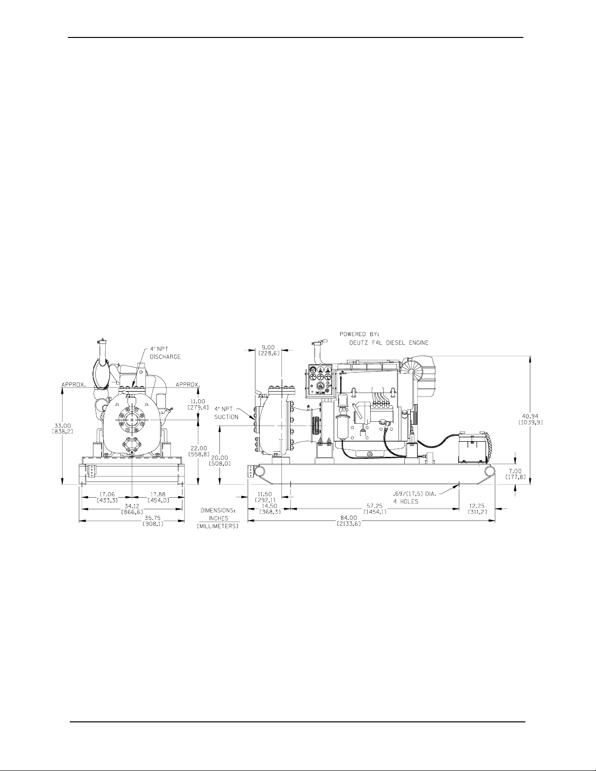
Pump Dimensions
SeeFigure1fortheapproximatephysicaldimensionsofthispump.
Figure 1. Pump Model 04B3--F4L
PREINSTALLATION INSPECTION
Thepump assemblywas inspectedandtested beforeshipment from the factory. Before installation,
inspect the pump for damage which may haveoc curred during shipment. Check as follows:
a. Inspect the pump and engine for cracks,
dents, damaged threads, and other obvious
damage.
b. Check for and tighten loose attaching hard-
ware. Since gaskets tend to shrink after drying, check for loose hardware at mating surfaces.
c. Carefully read all tags, decals, and markings
onthepumpassembly,and performallduties
indicated.
d. Check levels and lubricate as necessary. Re-
fer to LUBRICATION in the MAINTENANCE
PAGE B -- 1INSTALLATION
Page 9
OM--01216 0SERIES
AND REPAIR section of thismanualandper-
form duties as instructed.
e. If the pump and engine have been stored for
more than 12 months, some of the components or lubricants may have exceeded their
maximumshelflife.These mustbeinspected
or replaced to ensure maximum pump service.
If the maximum shelf life has been exceeded, or if
anything appears to be abnormal, contact your
Gorman-Rupp distributor or the factory to determinethe repair or updating policy. Donotput the
pump into service until appropriate action has
been taken.
Battery Specifications And Installation
Unlessotherw ise specified on the pump order,the
engine battery wa s not included with the unit. Refer to the following specifications when selecting a
battery.
age to equipment. Suction and discharge hoses and piping must be removed from the pump before lifting.
Lifting
Use lifting equipment with a capacity of at least
7,650 pounds (3540 kg.). The pump weighs approximately1,560pounds (708kg.), notincluding
the weight of any customer installed options.Customerinstalledequipmentsuchas suctionanddischargepipingmustbe removedbefore attempting
to lift.
Thepumpassemblycanbeseriously
damagedifthecablesorchainsused tolift
andmovetheunitare improperlywrapped
around the pump.
Alignment
Table 1. Battery Specifications
Voltage
12 Volts
Cold
Crank
Amps
@0
_ F
960 ---975
Reserve
Capacity
@80
_ F
(Minutes)
365
Amp/
Rating
175
Hr.
Approx.
Overall
Dims.
(Inches)
20.5L
x
8.75W
x
9.75H
Refer tothe information accompanyingthe battery
and/or electrolytesolutionfor activationandcharging instructions.
Beforeinstalling thebattery,cleanthe positive and
negative cable connectors, and the battery terminals. Secure the battery by tightening the
holddown brackets. The terminals and clamps
maybecoated with petroleumjellyto retard corrosion. Connect and tighten the positive cable first,
then the negative cable.
POSITIONING PUMP
Use lifting and moving equipment in
good repair and with adequate capacity
toprevent injuriestopersonnelordam-
Thealignmentofthe pumpendand enginearecritical for trouble-free performance. During repair of
thepumpend, refertoSecuring Intermediateand
Drive Assembly to Engine in MAINTENANCE
AND REPAIR, Section E for Details.
Mounting
Locatethepump inanaccessibleplaceascloseas
practicalto the liquidbeingpumped. Levelmounting is essential for proper operation.
The pump may have to be supported or shimmed
to provide for level operation or to eliminate vibration.
If the pump has been mounted on a moveable
base,makecertainthebaseisstationarybysetting
the brakeandblocking thewheelsbefore attempting to operate the pump.
To ensure sufficient lubrication and fuel supply to
the engine, do not position the pump and engine
morethan 15_ off horizontal for continuousoperation. The pump and engine may be positioned up
to 30_ off horizontal for intermittent operation
only;however,the enginemanufacturershouldbe
consulted for continuous operation at angles
greater than 15_.
PAGE B -- 2 INSTALLATION
Page 10

0SERIES OM--01216
SUCTION AND DISCHARGE PIPING
Pump performance is adversely effected by increased suction lift, discharge elevation, and friction losses. Contact the factory to be sure your
overall application allows pump to operate within
thesafeoperationrange.
Materials
Either pipe or hose maybe used for suction and
discharge lines; however, the materials must be
compatiblewiththe liquidbeingpumped. Ifhoseis
used in suction lines, it must be therigid-wall, reinforcedtype to prevent collapseunder suction.Using piping couplings in suction lines is not recommended.
Line Configuration
Keep suction and discharge lines as straight as
possible to minimize friction losses. Make minimum use of elbows and fittings, which substantiallyincreasefriction loss.If elbowsarenecessary,
use the long-radius type to minimize friction loss.
Connections to Pump
Before tightening a connecting flange, align it exactlywith the pump port. Never pulla pipe lineinto
place by tightening the flange bolts and/or couplings.
Lines near the pump must be independently supported to avoid strain on the pump which could
cause excessive vibration, decreased bearing life,
and increased shaft and seal wear. If hose-type
linesare used,they shouldhaveadequatesupport
to secure them when filled with liquid and under
pressure.
Gauges
Most pumps are drilled and tapped for installing
discharge pressure and vacuum suction gauges.
If these gauges are desired for pumps that a re not
tapped, drill and tap the suction and discharge
lines not less than 18 inches from the suction and
discharge ports and install the lines. Installation
closer to the pump may result in erratic readings.
SUCTION LINES
Toavoidair pocketswhichcould affectpump priming, thes uction line must be as short and direct as
possible.Whenoperationinvolvesasuctionlift,the
line must always slope upward to the pump from
the source of the liquid being pumped; if the line
slopes down to the pump at any point along the
suction run, air pockets will be created.
Fittings
Suction lines should be the same size as the pump
inlet. If reducers are used in suction lines, they
should be the eccentric type, and should be installedwith the flat part of the reducers uppermost
to avoid creating air pockets. Valves are not normally used in suction lines, but if a valve is used,
install it with the stem horizontal to avoid air pockets.
Strainers
If a strainer is furnished with the pump, be certain
touse it;any sphericalsolidswhichpassthrougha
strainer furnished with the pump will also pass
through the pump itself.
If a strainer is not furnished with the pump, but is
installed by the pump user, make certain that the
total area of the openings in the strainer is at least
three or four times the cross section of the suction
line,and that the openings willnot permit passage
of solids larger than the solids handling capability
of the pump.
Thispump isdesignedtohandle up to 1/2-inchdiameter spherical solids.
Sealing
Since even a slight leak will affect priming, head,
and capacity, especially when operating with a
high suction lift, all connections in the suction line
should be sealed with pipe dope to ensure an airtight seal. Follow the sealant manufacturer’s recommendations when selecting and applying the
pipe dope. The pipe dope should be compatible
with the liquid being pumped.
Suction Lines In Sumps
If a single suction line is installed in a sump, it
should be positioned away from the wall of the
sumpata distance equal to1 1/2 times the diameter of the suction line.
PAGE B -- 3INSTALLATION
Page 11
OM--01216 0SERIES
If there is a liquid flow from an open pipe into the
sump, the flow should be kept away from the suctioninlet because theinflowwillcarryair downinto
the sump, and air entering the suction line will reduce pump efficiency.
Ifitis necessary to positioninflowclose to the suctioninlet, installa bafflebetween theinflowandthe
suctioninlet at a distance 1-1/2 times the diameter
of the suction pipe. The baffle will allow entrained
air to escape from the liquid before it is drawn into
the suction inlet.
If two suction lines are installed in a single sump,
theflow pathsmay interact,reducing theefficiency
of one or both pumps. To avoid this, position the
suction inlets so that they are separated by a distance equal to at least 3 times the diameter of the
suction pipe.
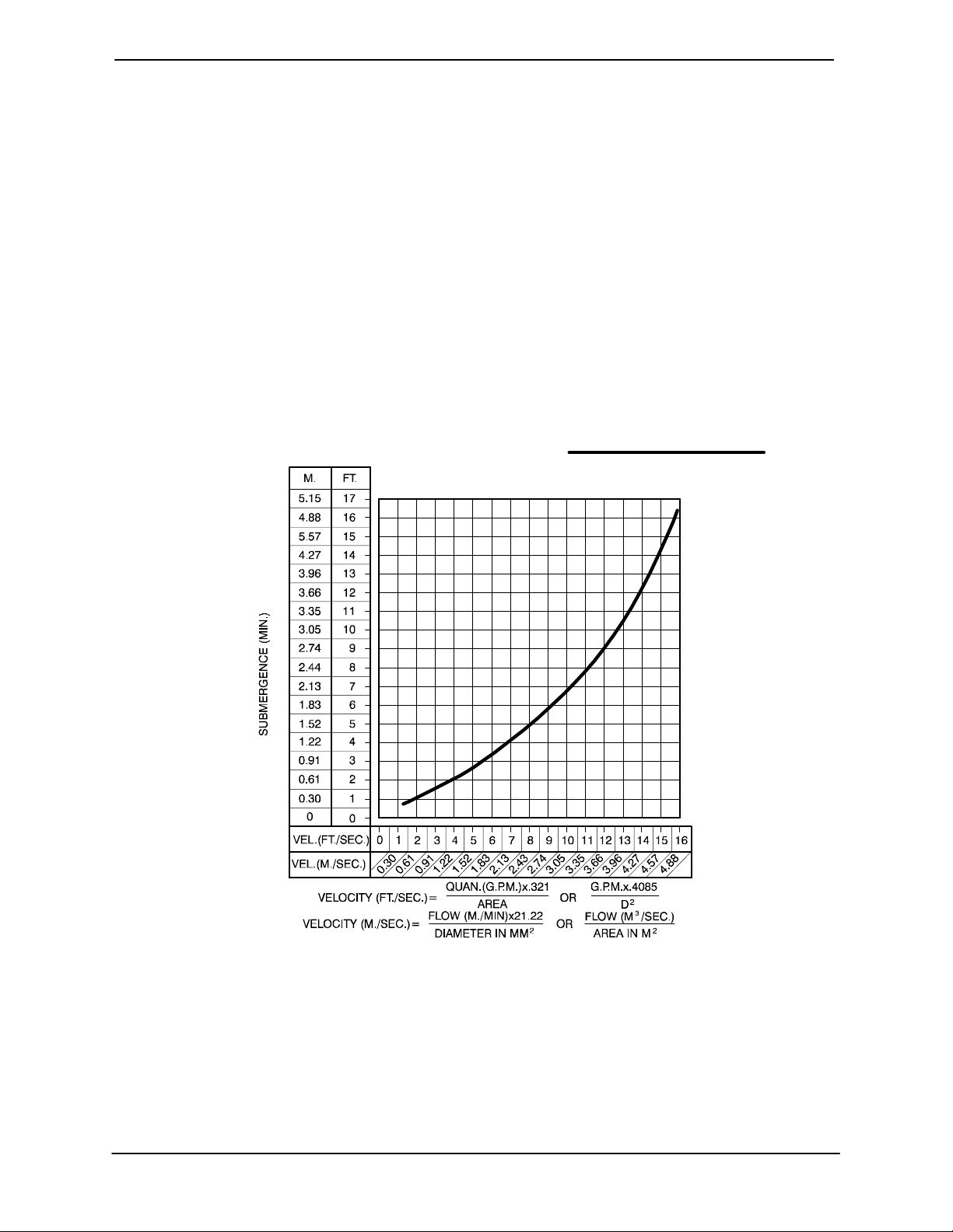
Suction Line Positioning
The depth of submergence of the suction line is
critical toefficient pump operation. Figure 2 shows
recommended minimum submergence vs. veloc-
ity.
NOTE
The pipe submergence required may be reduced
by installing a standard pipe increaserfitting at the
endof the suctionline. The largeropening size will
reduce the inlet velocity. Calculate the required
submergence using the following formula based
on the increased opening size (area or diameter).
Figure 2. Recommended Minimum Suction Line Submergence vs. Velocity
FLOAT SWITCHES
Installation
The standard pump is not furnished with a means
to automatically regulate liquid level. However, if
the unit is equipped with the optional auto-start
control system, the pump can be conformed to
PAGE B -- 4 INSTALLATION
start a nd stop as the liquid level in the wet well or
sump risesand falls. Theautostartoptionemploys
eitherasingle ordoublefloatswitch system,where
a bulb raises or lowers (floats) with the liquid level,
thus activating an enclosed miniature switch. The
floats are equipped with a socket type connector
that plugs into a matching receptacle on the auto start control box.
Page 12

0SERIES OM--01216
Standard floatsare equipped with 50 feet(15,2m)
of cable.
When installing the floats, note the following:
a. Be sure to provide sufficient room in the wet
well or sump so that floats do not get obstructedordrawn intothesuctionline.Ifaflexible suction hose is used, it may be extended
tolayalongthebottomofthe wetwellorsump
and the float can be attached to the hose
abovethe point where it bends along the bottom. Direct the suction line toward the flow,
and the float(s) away fromthe flow.If a standpipe is available, attach the float switch cable
to the standpipe in the sump at the approximatedesiredliquidlevel.
ENGINE
CONTROL
BOX
ON
(Emptying)
OFF
(Filling)
OPERATING
CABLE
TETHER
RANGE
(See Table Below)
POINT
OFF
(Emptying)
1.25” Pipe
(Not Furnished)
ON
(Filling)
b. In a single floatsystem, the cablecan be teth-
ered to the suction line or standpipeapproximately 6 inches (152 mm) above the float.
This setting allows approximately 9 inches
(229 mm) of liquid rise between pump start/
stop.The start/stopintervalmay beincreased
by extending the float end of the cable. The
liquid level in the sump will increase approximately8 inches (203mm) between start/stop
intervals for every 6 inches (152 mm) of cable
increase.
c. If a double float switch system is used, posi -
tion the “Start” float at the desired high water
level in the sump, and the “Stop” float at the
desired low water level in the pump.
d. Refer to Figure 3 for additional float switch
data.
3.0
(0.9)
2.5
(.76)
2.0
(0.6)
1.5
(.46)
1.0
(0.3)
0.5
(.15)
1.0
(0.3)
APPROXIMATEFREECORDLENGTHINFT.(M)
2.0
(0.6)
3.0
(0.9)
4.0
(1.2)
Figure 3. Float Switch Data
DISCHARGE LINES
Siphoning
Donot terminate the discharge lineat a level lower
than that of the liquid being pumped unless a siphon breaker is used in the line. Otherwise, a siphoning action causing damage to the pump
could result.
Valves
If a throttlingvalve is desired in the discharge line,
useavalveaslargeasthelargestpipetominimize
friction losses. Never install a throttling valve in a
suction line.
Withhighdischarge heads,itis recommendedthat
a t hrottling valve and a system check valve be installed in the discharge line to protect the pump
from excessive shock pressure and reverse rotation when it is stopped.
Iftheapplicationinvolvesa highdischarge
head, gradually close the discharge
throttling valve before stopping the pump.
Bypass Lines
If a system check valve is used due to high discharge head, it may be necessary to vent trapped
PAGE B -- 5INSTALLATION
Page 13

OM--01216 0SERIES
airfromthetop ofthepump duringtheprimingprocess.This maybeaccomplishedby installingabypass line from the top of the pump, back to the
source of the liquid. The end of the bypass line
must be submerged. The line must be large
enough to prevent clogging, but not so large as to
affect pump discharge capacity.
PAGE B -- 6 INSTALLATION
Page 14

0SERIES
OM--01216
OPERATION --- SECTION C
Review all SAFETY information in Section A.
Follow the instructions on all tags, labels and
decals attached to the pump.
Do not operate an i n ternal combustion
engine in an explosive atmosphere.
When operating internal combustion
engines in an enclosed area, make ce rtain that exhaust fumes are piped to the
outside. These fumes contain carbon
monoxide, a deadly gas that is colorless, tasteless, and odorless.
This pump is designed to handle clear
liquids containing specified entrained
solids.Donotattempttopumpvolatile,
corrosive, or flammable materials, or
any liquids which may damage the
pumporendange r personnelas a result
of pump failure.
PRIMING
Install the pump and piping as described in INSTALLATION. Make sure that the piping connec-
tions are tight, and that the pump is securely
mounted. Check that the pump is properly lubricated (see LUBRICATION in MAINTENANCE
AND REPAIR).
notprimewhen dry.Extended operationof
a dry pump willdestroythesealassembly.
Add liquid to the pump casing w hen:
1. The pump is being put into service for the
first time.
2. Thepump has notbeenusedfora considerable length of time.
3. The liquid in the pump casing has evaporated.
When installed in a flooded suction application,
simply open the system valves and permit the incoming liquid to evacuate the air. After the pump
and piping system have completely filled, evacuate any remaining air pockets in the pump or suctionlineby looseningpipeplugoropeningbleeder
valves.
Once the pump casing has been filled, the pump
will prime and reprime as necessary.
After filling the pump casing, reinstall
and tighten the fill plug. Do not attempt
to operate the pump unless all connecting piping is securely installed. Otherwise, liquid in the pump forced out under pressure could cause injury to personnel.
Tofill the pump, remove the pump casing fill cover
or fill plug in the top of the casing, and add clean
liquid until the casing is filled. Replace the fillcover
or fill plug before operating the pump.
This pump is self priming, but the pump should
never be operated unless there is liquid in the
pump casing.
STARTING
Ifthe pump is equipped with the optional automatic starting system, it is sub-
Never operate this pump unless there is
liquid in the pump casing. The pump will
OPERATION PAGE C -- 1
ject to automatic restart. Keep hands
and clothing away from the unit to pre-
Page 15

OM--01216 0SERIES
vent injury during automatic operation.
Disconnect the positive battery cable
before performing any maintenance.
Failuretodosomayresultinserious
personal injury.
Consult the operations manual furnished with the
engine.
Manual Starting
On initial start-up, set the engine speed at the halfthrottleposition.Turnthe keyswitch on the control
boxto the “START”positionuntil the enginestarts.
Release the key and the switch will return to the
“RUN” position.
After the engine starts and the unit is fully primed,
adjust the engine RPM until the desired flow rateis
achieved.
Pump speed and operating condition
points must be within the continuous performance range shown on the curve on
page E-1.
the keyswitch in the “AUTO START” position by
pressing thewhite“MAN”button onthecontrol.The
“Single Lightning Bolt” light on the control will illuminate in conjunction with an audible alarm before
the unit starts. The unit can then be stopped manually by pressing the “OFF/SET” button.
In the auto-start mode, the “SingleLightningBolt”
light will illuminate in conjunction with an audible
alarm when the liquid level in the sump or wet well
rises and activates the float(s). The light will blink
and the alarm will sound for approximately 8 seconds before the unit starts.
Whentheliquidlevelinthesumpor wetwell issufficiently pumped down, the unit will automatically
shut down.
NOTE
If the keyswitch is moved to the “OFF” position
while in the auto-start mode, the engine will stop.
However, the auto-start process will continue as
soonas thekeyswitch is moved backtothe “AUTO
START” position. Tocancel the auto-start process,
press the “OFF/SET” button.
Automatic Starting
If the unit is equipped with the optional autostart
control system, install the float(s) as described in
INSTALLATION, Section B.
Followtheprocedures outlined formanual starting
and throttle adjustment, then turn the key to the
“AUTO START” position.
NOTE
For securitypurposes, thekey canbe removedwith
the switch in the “AUTO START” position.
Press and hold the white “AUTO” button on the
controlpanel untilthered “AUTO”lightilluminates.
The auto-start system is now armed.
NOTE
The unit can continue to be started manually with
Thecontrolpanelisequipped with high oiltemperature, lowoil pressure, V-beltand start failure(3 attempts)safetyshutdowns. Ifanyoftheseproblems
occur,the red “Double LightningBolt”lightwillilluminate to indicate a system fault. When the problemis corrected,pressthe“OFF/SET”buttontoreset the control.
NOTE
The “OFF/SET” button has dual functionality when
in program mode. If necessary, consult the factory
for details on programming functions.
The unit can be started manually with the keyswitch in the “AUTO START” position by pressing
the white “MAN” button. The “Single Lightning
Bolt” light will illuminatein conjunction with an audible alarm before the unit starts.
Stop the unit manually bypressing the “OFF/SET”
button.
OPERATIONPAGE C -- 2
Page 16

0SERIES
OM--01216
OPERATION
Lines With a Bypass
Close the discharge throttling valve (if so
equipped) so that the pump will not have to prime
against the weight of the liquid in the discharge
line. Air from the suction line will be discharged
throughthe bypassline backto thew et wellduring
the priming cycle. When the pump is fully primed
andliquidisflowingsteadilyfromthebypassline,
open the discharge throttling valve. Liquid will then
continueto circulate through the bypass linewhile
the pump is in operation.
Lines Without a Bypass
Open all valves in the discharge line and start the
power source. Priming is indicated by a positive
reading on the discharge pressure gauge or by a
quieteroperation. The pump maynot primeimmediately because the suction line must first fill w ith
liquid. If the pump fails toprimewithin fiveminutes,
stop it and check the suction line for leaks.
Afterthepump hasbeen primed,partiallyclosethe
discharge line throttling valve in order to fill the line
slowly and guard against excessive shock pressure which could damage pipe ends, gaskets,
sprinkler heads, and any other fixtures connected
to the line. When the discharge line is completely
filled,adjustthethrottlingvalve tothe requiredflow
rate.
boil, build pressure, and cause the pump to rupture or explode. If overheating occurs, stop the
pump and allow it to cool before servicing it. Refill
the pump casing with cool liquid.
Do not remove plates, covers, gauges,
pipe plugs, or fittings from an overheated pump. Vaporpressure withinthe
pump can cause parts being disengagedtobe ejectedwithgreat force.Allow the pump to cool before servicing.
Strainer Check
If a suction strainer has been shipped with the
pump or installed by the user, check the strainer
regularly, and clean it as necessary. The strainer
shouldalsobe checkedifpumpflowratebeginsto
drop. If a vacuum suction gauge has been installed, monitor and record the readings regularly
to detect strainer blockage.
Never introduce air or steam pressure into the
pump casingor piping to removea blockage.This
could result in personal injury or damage to the
equipment. If backflushing is absolutely necessary,liquid pressuremustbe limited to50% oft he
maximum permissible operating pressure. Since
this pump is fitted with a Gorman-Rupp double
grease lubricated seal, the maximum incoming
pressure must be reduced to 10 p.s.i.
Leakage
No leakage should be visibleat pump mating surfaces, or at pump connections or fittings. Keep all
lineconnectionsand fittingstight tomaintain maximum pump efficiency.
Liquid Temperature And Overheating
The maximum liquid temperature for this pump is
160_ F(71_C).Donotapplyitata higher operating
temperature.
Overheating can occur if operated with the valves
in the suction or discharge lines closed. Operating
against closed valves could bring the liquid to a
OPERATION PAGE C -- 3
Pump Vacuum Check
Withthe pump inoperative,installa vacuumgauge
in the system, using pipe dope on the threads.
Block the suction lineandstart thepump. At operating speed the pump should pull a vacuum of 20
inches (508,0 mm) or more of mercury. If it does
not, check for air leaks in the seal, gask et, or discharge valve.
Openthe suctionline,andread thevacuum gauge
with the pump primed and at operation speed.
Shut offthe pump. The vacuumgaugereading will
immediately drop proportionate to static suction
lift,andshouldthenstabilize.Ifthevacuumreading
falls off rapidly after stabilization, an air leak exists.
Page 17

OM--01216 0SERIES
Before checking for the source of the leak, check
the point of installation of the vacuum gauge.
STOPPING
Manual Stopping
In the manual mode, reduce the throttle speed
slowly, and allow the engine to idle briefly before
switching the HAND-OFF-AUTO switch to ‘OFF’.
If the application involves a high discharge
head, gradually close the discharge
throttling valve before stopping the pump.
Afterstoppingthe pump,switchoffthe engineignition and disconnect the positive battery cable to
ensure that the pump will remain inoperative.
Automatic Stopping
In the automatic mode, the pump will stop when
the liquid in the wet well or sump lowers and activatesthe“Off” floatswitch(s).Thepump willrestart
automatically when the liquid rises and activates
the “On” float switch(s).
Safety Shutdown System
The unit is equipped with a safety system to automaticallyshut down the engine under certain conditions. The engine will automatically shut down:
1. If the engine exceeds its safe operating temperature.
2. If the engine oil pressure drops below design
limits.
3. Iftheenginefailstostartwithinapre-setperiod of time.
Shouldany oft he safety featurescausethe engine
toshut down,the cause must bedeterminedand
correctedbeforeputtingtheunitback intoservice.
The engine will not restart until the HAND-OFFAUTOswitch has been returned to the ‘OFF’ position for at least 10 seconds.
Allsafetyshutdown features are pre-set at the factory for optimum performance and safety; do not
attempt to adjust these settings.
Neverdisconnectanyofthe safetyshutdown features; this will void the warran-
and could result in serious damage to
ty
theuni t and/orinjuryto personnel.Safety shutdown features are pre-set at the
factory; do not
attempt to adjust any of
the settings. Determine the cause of
shutdown before putting the unit back
into service. Consult the factory for additional information.
OPERATIONINEXTREMEHEAT
The safety shutdown system will automatically
stop the unit if engine operating temperature exceeds design limits. If engine over-temperature
shutdown occurs, allow the unit to cool before restarting.
If engine overheating continues, check the engine
lubricant level and viscosity. Consult the engine
operation manual for the recommended lubricant
for operation in extreme heat.
If the unit is equipped with the optional auto-start
control,the float(s)may need to be adjusted to allow shorter run and longer coolingperiods, ifpossible.
4. If the engine speed exceeds the safe operating range.
5. Iftheenginefanbeltbreaks.
Lights onthe control panelwillindicatewhich ofthe
safety features has caused the engine to shut
down.
Ifthe pump is equipped with the optional automatic starting system, it is subject to automatic restart. Keep hands
and clothing away from the unit to prevent injury during automatic operation.
Disconnect the battery before perform-
OPERATIONPAGE C -- 4
Page 18

0SERIES
OM--01216
ing any maintenance. Failure to do so
may result in serious personal injury.
BEARING TEMPERATURE CHECK
Bearingsnormallyrun at highert han ambient temperatures because of heat generated by friction.
Temperatures up to 160_F(71_C) are considered
normalforbearings, andthey canoperatesafelyto
at least 180_F(82_C).
Checkingbearingtemperatures byhand isinaccurate. Bearing temperatures can be measured accurately by placing a contact-type thermometer
against the housing. Record this temperature for
future reference.
A sudden increase in bearing temperatures is a
warning that the bearings are at the pointoffailing
to operate properly.Make certain that the bearing
lubricant is of the proper viscosity and at the correct level (see LUBRICATION in Section E). Bear-
ing overheating can also be caused by shaft
misalignment and/or excessive vibration.
When pumps are first started, the bearings may
seem to run at temperatures above normal. Con tinued operation should bring the temperatures
down to normal levels.
Cold Weather Preservation
In below freezing conditions, drain the pump to
preventdamagefrom freezing. Also,clean outany
solids by flushing w ith a hose. Operate the pump
for approximatelyone minute; this willremove any
remaining liquid that could freeze the pump rotating parts. If the pump will be idle for more than a
few hours, or if it has been pumping liquids containing a large amount of solids, drain the pump,
and flush it thoroughly with clean water .T oprevent
large solids from clogging the drain port and preventing the pump from completely draining, insert
a rod or stiff wire in the drain port, and agitate the
liquid during the draining process. Clean out any
remaining solids by flushing with a hose.
OPERATION PAGE C -- 5
Page 19

0SERIES
OM--01216
TROUBLESHOOTING --- SECTION D
Review all SAFETY information in Section A.
Beforeattemptingto openorservicethe
pump:
1. Familiarize yourself with this man ual.
2. Set the HAND-OFF-AUTO switch to
‘OFF’, and disconnect the positive
battery cable to ensure that the
pump will remain inoperative.
3. Allow the pump to completely cool
if overheated.
4. Check the temperature before
opening any covers, plates, or
plugs.
5. Close the suction and discharge
valves.
6. Vent the pump slowly and cautiously.
7. Drain the pump.
Ifthe pump is equipped with the optional automatic starting system, it is subject to automatic restart. Keep hands
and clothing away from the unit to prevent injury during automatic operation.
Disconnect the positive battery cable
before performing any maintenance.
Failuretodosomayresultinserious
personal injury.
TROUBLE POSSIBLE CAUSE PROBABLE REMEDY
PUMP FAILS TO
PRIME
PUMP STOPS OR
FAILS TO DELIVER
RATED FLOW OR
PRESSURE
Not enough liquid in casing. Add liquid to casing. See PRIMING.
Suction check valve contaminated Clean or replace check valve.
or damaged.
Air leak in suction line. Correct leak.
Lining of suction hose collapsed. Replace suction hose.
Leaking or worn seal or pump gasket. Check pump vacuum. Replace
leakingorwornsealorgasket.
Suction lift or discharge head too high. Check piping installation and
install bypass line if needed. See
INSTALLATION.
Strainer clogged. Check strainer and clean if
necessary.
Suction check valve or foot valve Clean valve.
clogged or binding.
Air leak in suction line. Correct leak.
Lining of suction hose collapsed. Replace suction hose.
Leaking or worn seal or pump gasket. Check pump vacuum. Replace
leakingorwornsealorgasket.
Strainer clogged. Check strainer and clean if
necessary.
TROUBLESHOOTING PAGE D -- 1
Page 20

OM--01216
TROUBLE POSSIBLE CAUSE PROBABLE REMEDY
0SERIES
PUMP STOPS OR
FAILS TO DELIVER
RATED FLOW OR
PRESSURE (cont.)
PUMP REQUIRES
TOO MUCH
POWER
PUMP CLOGS
FREQUENTLY
Suction intake not submerged at Check installation and correct
proper level or sump too small. submergence as needed.
Impellerorotherwearingpartsworn Replacewornordamagedparts.
or damaged. Check that impeller is properly
centered and rotates freely.
Impeller clogged. Free impeller of debris.
Pump speed too s low. Check engine output; consult
engine operation manual.
Suction lift or discharge head too high. Check piping installation and
install bypass line if needed. See
INSTALLATION.
Pump speed too high. Check engine output.
Discharge head too low. Adjust discharge valve.
Liquid solution too thick. Dilute if possible.
Bearing(s) frozen. Disassemble pump and check
bearing(s).
Liquid solution too thick. Dilute if possible.
Discharge flow too slow. Open discharge valve fully to in---
crease flow rate, and run power
source at maximum governed
speed.
EXCESSIVE NOISE
BEARINGS RUN
TOO HOT
Discharge line clogged or restricted; Check discharge lines; straighten
hose kinked. hose.
Suction check valve or foot valve Clean valve.
clogged or binding.
Cavitation in pump. Reduce suction lift and/or friction
losses in suction line. Record
vacuum and pressure gauge
readings and consult local
representative or factory.
Pumping entrained air. Locate and eliminate source of air
bubble.
Pump or drive not securely mounted. Secure mounting hardware.
Impeller clogged or damaged. Clean out debris; replace damaged
parts.
Bearing temperature is high, but Check bearing temperature regu---
within limits. larly to monitor any increase.
Loworincorrectlubricant Checkforpropertypeandlevel
of lubricant.
Suction and discharge lines not Check piping installation for proper
properly supported. support.
Drive misaligned. Align drive properly.
TROUBLESHOOTINGPAGE D -- 2
Page 21

0SERIES
OM--01216
PREVENTIVE MAINTENANCE
Sincepump applicationsareseldomidentical,and
pump wear is directly affected by such things as
the abrasive qualities, pressure and temperature
oftheliquidbeingpumped, thissection isintended
only to provide general recommendations and
practices for preventive maintenance. Regardless
of the application however,following a routine preventive maintenance schedule will help assure
trouble-free performance and long life from your
Gorman-Rupp pump. For specific questions concerning your application, contact your GormanRupp distributor or the Gorman-Rupp Company.
Record keeping is an essential component of a
good preventive maintenance program. Changes
in suction and discharge gauge readings (if so
equipped) between regularly scheduled inspections can indicate problems that can be corrected
before system damage or catastrophic failure occurs.The appearanceof wearingpartsshouldalso
bedocumented ateach inspectionfor comparison
as well. Also, if records indicate that a certain part
(such as the seal) fails at approximately the same
duty cycle, the part can be checked and replaced
beforefailureoccurs,reducing unscheduleddown
time.
For new applications, a first inspection of wearing
partsat250 hourswillgiveinsightintothewearrate
foryourparticularapplication.Subsequentinspections should be performed at the intervals shown
on the chart below. Critical applications should be
inspected more frequently.
Preventive Maintenance Schedule
Service Interval*
Item
General Condition (Temperature, Unusual
Noises or Vibrations, Cracks, Leaks,
Loose Hardware, Etc.) I
Pump Performance (Gauges, Speed, Flow) I
Bearing Lubrication I R
Seal Lubrication (And Packing Adjustment,
If So Equipped) I R
V-Belts (If So Equipped) I
Air Release Valve Plunger Rod (If So Equipped) I C
Front Impeller Clearance (Wear Plate) I
Rear Impeller Clearance (Seal Plate) I
Check Valve I
Pressure Relief Valve (If So Equipped) C
Pump and Driver Alignment I
Shaft Deflection I
Bearings I
Bearing Housing I
Piping I
Driver Lubrication --- See Mfgr’s Literature
Daily Weekly Monthly Semi-
Annually
Annually
Legend:
I = Inspect, Clean, Adjust, Repair or Replace as Necessary
C= Clean
R= Replace
* Service interval based on an intermittent duty cycle equal to approximately 4000 hours annually.
Adjust schedule as required for lower or higher duty cycles or extreme operating conditions.
TROUBLESHOOTING PAGE D -- 3
Page 22

0SERIES OM--01216
PUMP MAINTENANCE AND REPAIR - SECTION E
MAINTENANCE AND REPAIR OF THE WEARING PARTS OF THE PUMP WILL MAINTAIN PEAK
OPERATING PERFORMANCE.
STANDARD PERFORMANCE FOR PUMP MODEL 04B3--F4L
Based on 70_ F(21_ C) clear water at sea level
with minimumsuction lift.Since pump installations
areseldomidentical,yourperformancemaybe difference due to such factors as viscosity, specific
gravity, elevation, temperature, and impeller trim.
Never tamper with the governor to gain
more power. The governor establishes
If your pump serial number is followed by an “N”,
your pump is NOT astandardproductionmodel.
Contact the Gorman-Rupp Company to verifyperformance or part numbers.
MAINTENANCE & REPAIR PAGE E -- 1
safe operating limits that should not be
exceeded. The maximum continuous
operating speed for this pump is 2400
RPM.
Page 23

SECTION DRAWING
0SERIESOM-- 01216
Figure 1. 04B3---F4L Pump Model Assembly
MAINTENANCE & REPAIRPAGE E -- 2
Page 24

0SERIES OM--01216
PARTS LIST
Pump Model 04B3---F4L
(From S/N 1242057 Up)
Ifyourpump serialnumber is followedby an “N”,your pumpis NOT a standard production model. Contact
the Gorman-Rupp Company to verify part numbers.
ITEM
NO.
10 FUEL RETURN LINE 14294 24030 1
11 MUFFLER GUARD ASSY 42331---031 --- ------ 1
12 DEUTZ F4L 912D ENG 29217---043 --- --- --- 1
13 CAUTION DECAL 38816---169 --- - -- --- 1
14 BAT T E RY B O X A S S Y GR P 40 --- 08 C --- --- --- 1
15 ---HEX HD CAPSCREW B0607 15991 2
16 ---FLAT WASHER K06 15991 2
17 ---HEX NUT W/FLANGE 21765---314 --- ------ 2
18 ---GRND CABLE ASSY 47311---064 --- --- --- 1
19 ---BATT BOX LID ASSY 42113---012 24150 1
20
21 ---BATTERY TAG 38818- --506 ------ --- 1
22 ---BATTERY BOX ASSY 42431---030 24150 1
23 ---STUD MOUNT 24631---006 --- --- --- 4
24 ---FLANGED HEX NUT 21765---314 --- ------ 8
25 ---T TYPE LOCKWASHER BL06 15991 1
26 POS CABLE ASSY 47311---114 ------ --- 1
27 HEX HD CAPSCREW B1017 15991 2
28 LOCKWASHER J10 15991 2
29 HEX NUT D10 15991 2
30 OIL DRAIN ASSY 46342---007 --- - -- --- 1
PART NAME PART
NUMBER
1 P U MP E N D A S S Y 04B3 --- (SA E 4/ 1 0) --- --- --- 1
2 CONTROL PANEL 48122---501 --- --- --- 1
3 EXHAUST ELBOW 31912---023 15990 1
4 WEATHER CAP S1331 --- ------ 1
5 FUEL RETURN LINE 11308F ------ --- 1
6 HOSE CLAMP 26518---641 --- -- ---- 2
7 HOSE BARB FITTING 26523---443 --- ------ 1
8 MALE CONNECTOR 26523---382 ------ --- 1
9 REDUCER ELBOW Q0402 11999 1
---12V BATTERY SEE OPTION LIST REF
MAT’L
CODE
QTY ITEM
NO.
31 HOSE INLET ASSY 46341---796 ------ --- 1
32 MALE CONNECTOR S1447 --- ------ 1
33 HEX HD CAPSCREW B1007 15991 4
34 LOCKWASHER J10 15991 4
35 HEX NUT D10 15991 4
36 FUEL TANK AND 46711---041 ------ --- 1
37 ---FUEL TANK ASSY 46711---042 ------ --- 1
38 ---FLANGED HEX NUT 21765---314 --- ------ 6
39 ---CARRIAGE BOLT AB0604 15991 6
40 ---FLAT WASHER K06 15991 6
41 ---TANK GRD ASSY 34851---178 15080 1
42 FLANGED HEX NUT 21765---314 --- ------ 10
43 FLAT WASHER K06 15991 10
44 HEX HD CAPSCREW B0604 15991 10
45 COMBINATION BASE 41566- --669 24150 1
46 HEX HD CAPSCREW B1010 15991 2
47 LOCKWASHER J10 15991 2
48 HEX NUT D10 15991 2
NOT SHOWN:
OPTIONAL:
PART NAME PART
NUMBER
GUARD ASSEMBLY
WARNING DECAL 2613FE ------ - -- 1
12V BATTERY 29331---506 --- ------ 1
WHEEL KIT GRP30---248F --- ------ 1
PRESSURE GAUGE 48312---012 --- --- --- 1
REPAIR MUFFLER 42331- --048 ------ --- 1
GUARD ASSEMBLY
MAT’L
CODE
QTY
INDICATES PARTSRECOMMENDEDFOR STOCK
MAINTENANCE & REPAIR PAGE E -- 3
Page 25

SECTION DRAWING
0SERIESOM-- 01216
Figure 2. 04B3---(SAE 4/10) Pump End Assembly
MAINTENANCE & REPAIRPAGE E -- 4
Page 26

0SERIES OM--01216
PARTS LIST
04B3---(SAE 4/10) Pump End Assembly
ITEM
NO.
10 RD HD MACH SCREW X0404 15991 2
11
12 LU B E F IT TING S1 91 --- --- --- 1
13 PIPE NIPPLE T0410 15079 1
14 PIPE COUPLING AE04 15079 1
15 CAP PLUG 25141---151 --- - -- --- 1
16 ALLEN HD SETSCREW GA0403 15990 1
17
18
19
20 INTERMEDIATE GUARD 42381---504 --- ------ 2
21 BEARING RET NUT 4329 10010 1
22 SPACER 13886 15990 1
23 RET AIN I N G R ING S2 1 5 --- --- --- 1
PART NAME PART
1 PUMP CASING 4820C 10010 1
2
IMPELLER 4803D 14000 1
SEAL ASSY 25271---207 --- ------ 1
3
4 DISCHARGE STICKER 6588BJ ------ --- 1
5 STUD C1010 15991 8
6 HEX NUT D10 15991 8
7
WEAR RING 3765A 10010 1
8 DISCHARGE FLANGE 1756 10010 1
9
DISCH FLANGE GASKET 1676GB 20000 1
BALL BEARING 23423---472 --- -- ---- 1
IMP ADJ SHIM SET 37J 17090 REF
SHAFT KEY N0607 15990 1
IMPELLER SHAFT 38517---517 1706H 1
NUMBER
MAT’L
CODE
QTY ITEM
NO.
24 RET AIN I N G R ING S2 1 5 --- --- --- 1
25 INTERMEDIATE 7765D 10010 1
26
27 STUD C1010 15991 12
28 HEX NUT D10 15991 12
29 SEAL PLATE 5792 10010 1
30
31
32 NAME PLATE 38818---018 13990 1
33 DRIVE SCREW BM#04---03 17000 4
34 PIPE PLUG P06 15079 1
35 STUD C0807 15991 6
36 HEX NUT D08 15991 6
37 COVER PLATE 4822 10010 1
38
39
40 SUCTION FLANGE 1756 10010 1
41 HEX HD CAPSCREW B1005S 15991 1
42 T TYPE LOCKWASHER AK10 15991 1
43 IMPELLER WASHER 5718 15990 1
44 HEX HD CAPSCREW C1010 15991 8
45 HEX NUT D10 115991 8
46 DISCHARGE STICKER 6588AG --- --- --- 1
47 FILL PLUG ASSY 48271---065 --- ------ 1
PART NAME PART
NUMBER
WEAR RING 6902 10010 1
PUMP CASING GASKET 4820G 20000 1
IMPELLER KEY N0408 15990 1
COVER PLATE GASKET 4822G 20000 1
SUCT FLANGE GASKET 1676GB 20000 1
MAT’L
CODE
QTY
INDICATES PARTSRECOMMENDEDFOR STOCK
MAINTENANCE & REPAIR PAGE E -- 5
Page 27

SECTION DRAWING
0SERIESOM-- 01216
Figure 3. 04B3---(SAE 4/10) Drive Assembly
PARTS LIST
ITEM
NO.
1 PILOT BUSHING ASSY 44144---003 ------ --- 1
2 COUPLING KIT 48112---001 --------- 1
3 ---BUSHING 24131---345 ------ --- 1
4 ---COUPLING ASSEMBLY 44165---011 --------- 1
5 ---LOCKWASHER 21171---536 --------- 8
6 ---SOCKET HD CAPSCREW 22644---220 --------- 8
7 HEX HD CAPSCREW 22645---164 --------- 12
8 LOCKWASHER 21171---511 --------- 12
PART NAME
PART
NUMBER
MAT’L
CODE
MAINTENANCE & REPAIRPAGE E -- 6
QTY
Page 28

OM--012160SERIES
PUMP AND SEAL DISASSEMBLY
AND REASSEMBLY
Review all SAFETY information in Section A.
Followtheinstructionson all tags,labeland de cals attached to the pump.
This pump requires little service due to its rugged,
minimum-maintenance design. However, if it becomesnecessarytoinspect orreplacethe wearing
parts, followthese instructionswhichare keyed to
thesectionalviews(seeFigures 1,2 and3) andthe
accompanying parts lists.
As described on the following pages, this manual
willalert personnel toknown procedures which require special attention, to those which could dam age equipment, and to those which could be dangerousto personnel. However,this manualcannot
possibly anticipate and provide detailed precautions for every situation that might occur during
maintenanceof theunit. Therefore,itis theresponsibilityof the owner/maintenance personnel to ensure that only safe, established maintenance proceduresare used, andthat anyproceduresnot addressedinthismanualareperformedonlyafterestablishingthat neitherpersonal safetynorpump integrity are compromised by such practices.
Before attempting to service the pump, switch off
theengineignitionanddisconnect thepositivebatterycabletoensure thatthe pumpwill remaininoperative. Close all valves in the suction and dis charge lines.
Forengine disassembly and repair, consult the literature supplied with the engine, or contact your
local engine representative.
3. Allow the pump to completely cool
if overheated.
4. Check the temperature before
opening any covers, plates, or
plugs.
5. Close the suction and discharge
valves.
6. Vent the pump slowly and cautiously.
7. Drain the pump.
Pump Disassembly
(Figure 2)
Beforeattemptingtoservicethepump, removethe
pump casing drain plug (34) and drain the pump.
Clean and reinstall the drain plug.
To service the wear ring (7), impeller (2), seal assembly (3), or seal plate (29), the pump casing (1)
mustbe separatedfromthebase andintermediate
(25).
Remove the suction and discharge lines. See Figure1,andremovethehardware(46, 47and 48)securing the casing to the base (45). Remove the
nuts(28)and useasuitablehoistand slingtoseparatethe pumpcasingandgasket(30)fromtheseal
plate and intermediate.
Use lifting and moving equipment in
good repair and with adequate capacity
toprevent injuriestopersonnelordamage to equipment. Suction and discharge hoses and piping must be removed from the pump before lifting.
Tieand tagany levelingshims usedunder the casing feet to ease reassembly.
Beforeattemptingto openorservicethe
pump:
1. Familiarize yourself with this man ual.
2. Switch off the engine ignition and
disconnect the positive battery
cable to ensure that the pump will
remain inoperative.
MAINTENANCE & REPAIR PAGE E -- 7
Inspect the wear ring (7) for excessive wear or
scoring.The wear ring issecured in the pumpcasing by a press fit. If replacement is required, use a
small bit to drill two holes through the ring horizontally, 180_ apart. Use a saw or chisel to complete
the cuts through the ring, and remove it from the
pump casing. Use caution not to damage the
pump casing bore when removing the wear ring.
Page 29

Use caution not to damage the pump casing bore when removing the wear ring.
0SERIESOM--01216
(Figure 3)
Support the intermediate using a hoist and sling,
and remove the hardware (7 and 8) securing it to
theenginebellhousing.Separatetheassemblies
by pulling the intermediate straight away from the
engine.
Impeller Removal
(Figure 2)
To remove the impeller (2), disengage the hardware(41,42 and 43).Install3/8---16UNCby 4-inch
longcapscrews inthetapped holesin the impeller.
Use thecapscrewsanda suitablepuller toremove
the impeller from the shaft. Use caution when removingthe impeller;tension on the sealspring will
be released as the impeller is removed. Retain the
impeller key (31).
Remove the impelleradjusting shims (17). Tie and
tag the shims or measure and record their thickness for ease of reassembly.
Seal Removal and Disassembly
(Figures 2 and 5)
Removethe spring. Apply oilto the shaft and work
it up under the rubber bellows. Slide the rotating
portionofthesealofftheshaft.
Remove the round head machinescrews (10) and
slide the seal plate and stationary element off the
impeller shaft as a unit. Press the stationary seal
element and O-ring out of the seal plate from the
back side.
Inspect the wear ring (26) for excessive wear or
damage. If replacement is required, use a suitable
puller to remove it from the seal plate.
As the assemblies separate, the flexible portionof
the couplingassembly(4) will remain on the shaft.
Toremovethe couplingfromt he shaft,unscrew the
two allen head setscrews from the bushing (3).
Screw one ofthe setscrews into the puller holeon
the circumference of the bushing. As the coupling
and bushing separate, remove the bushing, and
slide the coupling off the shaft. Remove the shaft
key (18, Figure 2).
It is not necessary to remove the outer ring of the
coupling from the engine flywheel unless the couplingmust be replaced. To removethe ring, disengage the hardware (5 and 6) securing it to the flywheel.
Inspect t he pilot bushing (1) for excessive wear. If
replacement is required, it can be easily removed
from the engine flywheel by making a hydraulic
ramfroma piece ofsteel bars tock. Turnthe ramto
a diameter of 0.983 inch (25 mm).
Whenperforming the following procedure,
grease can be ejected with great force.
Wear safety glasses or goggles to prevent
injury.
Completelypack the bore of the pilotbushingwith
grease. Insert theendof the ram intothe I.D.of the
bushing. Strike the ram sharply with a hammer,
compressing the grease, and forcing the bushing
out of the flywheel. Use additional grease as required, and continue to strike the ram until the
bushing is completely free.
Separating Intermediate and Drive Assembly
From Engine
(Figure 2)
To service the shaft (19), bearing (11) or drive assembly, the intermediate (25) must be separated
from the engine.
Shaft and Bearing Removal and Disassembly
(Figure 2)
When the pump is properly operated and maintained, the shaft and bearing should not require
disassembly. Disassemble the shaft and bearing
only when there is evidence of wear or damage.
MAINTENANCE & REPAIRPAGE E -- 8
Page 30

Shaft and bearing disassembly in the field
is not recommended. These operations
should be performed only in a properly
equipped shop by qualified personnel.
After separating the intermediatefrom the engine,
loosen the allen head setscrew (16) and unscrew
thebearing retainernut (21) fromtheintermediate.
NOTE
There are no provisions for draining the grease
fromtheintermediatecavity.Placea drip pan under
theintermediatebeforeremovingtheshaftand
bearing.
OM--012160SERIES
Cleanthebearingthoroughlyinfreshcleaningsolvent. Dry the bearing with filtered compressed air
and coat with light oil.
Thebearingmustbekeptfreeofalldirtand
foreign material. Failure to do so willgreatly shorten bearing life. Do not spin dry
bearings. This may scratch the balls or
races and cause premature bearing failure.
Rotatethe bearingbyhand tocheck forroughness
or binding and inspect the bearing balls. If rotation
is rough or the bearing balls are discolored, replace the bearing.
Place a block of wood against the impeller end of
the shaft (19) and tap the shaft, spacer (22) and
bearing (11) from the bearing bore.
Afterremoving theshaftand bearing, cleanandinspect the bearing in place as follows.
To prevent damage during removal from
theshaft, it is recommendedthat thebearing be cleaned and inspected in place.It
isstrongly recommended that thebearing
bereplacedany time theshaftandbearing
are removed.
Clean the intermediate, s haft and all component
parts (except the bearing) with a soft cloths oaked
in cleaning solvent. Inspect t he parts for wear or
damage and replace as necessary.
Most cleaning solvents are toxic and
flammable. Use them only in a well ventilated area free from excessive heat,
sparks, and flame. Read and follow all
precautions printed on solventcontainers.
The bearing tolerances provide a tight press fit
ontothe shaft and a snug slipfit into the intermediate. Replace the bearing, shaft, or intermediate if
the proper bearing fit is not achieved.
Remove the inboard bearing retaining ring (24)
andusing anarbor (orhydraulic)press removethe
bearing (11) from the shaft. It is not necessary to
remove the outboard bearing retaining ring (23)
from the shaft unless replacement is required. Remove the bearing spacer (22).
Shaftand Bearing Reassembly and Installation
Clean and inspect the bearing as indicated in
Shaft and Bearing Removal and Disassembly.
To prevent damage during removal from
theshaft, it is recommendedthat thebearing be cleaned and inspected in place.It
isstrongly recommended that thebearing
be replaced any time the shaft and and
bearings are removed.
Inspect the shaft for distortion, nicks or scratches
ordamage. D ress small nicks and burrswith a fine
file or emery cloth. Replace the shaft if defective.
Installthe outboard bearing retaining ring (23) if it
was removed. Replace the bearing spacer (22).
MAINTENANCE & REPAIR PAGE E -- 9
Page 31

0SERIESOM--01216
NOTE
If ahot oil bathis used to heat thebearing, boththe
oil and the container must be absolutely clean. If
the oil has been previously used, it must be thor-
oughly filtered.
Thebearing maybe heatedto ease installation.An
induction heater, hot oil bath, electric oven, or hot
plate may be used to heat the bearing. Bearings
should never be heated with a direct flame or directly on a hot plate.
NOTE
Positionthebearing ontheshaftas indicated inFigure 4.
BALL LOADING
DIRECTIONOF
THRUST
GROOVE POSITIONED
AWAY FROM
LOADING
GROOVE
IMPELLER
Heat the bearing to a uniform temperature no
higher than 250_F (120_C), and slide the bearing
ontothe shaft until fullyseated against the bearing
spacer. This should be done quickly, in one continuous motion, to prevent the bearing from cooling and sticking on the shaft.
Use caution when handling hot bear ings to prevent burns.
BALL LOADING
DIRECTIONOF
THRUST
GROOVE POSITIONED
TOWARD
LOADING
GROOVE
IMPELLER
INSTALLATION OF NEW DEPARTURE OR
BCA/FEDERAL MOGAL 5300W SERIES BEARINGS
(OPEN OR ENCLOSED IMPELLERS)
Figure 4. Bearing Positioning
After the bearing has been installed and allowed to
cool, check to ensure that it has not moved in
shrinking. If movement has occurred, use a suitable sized sleeve and a press to reposition the
bearing.
Ifheatingthebearingis notpractical,usea suitable
sizedsleeveandan arbor(orhydraulic)press toinstall the bearing on the shaft.
When installing the bearing on the shaft,
never press or hit against the outer race,
balls, or ball cage. Press only on the inner
race.
Packthe bearing by hand with No. 0 lithiumbased
grease until the bearing balls are thoroughly lubri-
INSTALLATIONOF MRC/SKF5300M OR
FAFNIR 5300W SERIES BEARINGS
(OPEN OR ENCLOSED IMPELLERS)
cated. Secure the bearing on the shaft with the inboard bearing retaining ring (24).
Slide the shaft and assembled bearing into the intermediate bore from the drive end until the bearing seats squarely against the bore shoulder.
When installing the shaft and bearing into
the bearing bore, push against the outer
race. Never hit the balls or ball cage.
Installthe spacer(22)in theintermediate. Packthe
intermediate w ith 2/3 lb. (0.3 kg.) of No. 0 lithium
based grease (approximately 1/3 full).
Screw the bearing retaining nut (21) into the intermediate and check the shaft endplay. Adjust the
bearing retaining nut to establish the correct
MAINTENANCE & REPAIRPAGE E -- 10
Page 32

OM--012160SERIES
endplay,and secure the bearingretaining nutwith
the setscrew (16).
NOTE
Impellershaftendplayshouldbe between.002and
.010inch(0,05mmto0,25mm). Adjustthebearing
retaining nut to obtain the correct endplay.
Securing Intermediate and Drive Assembly To
Engine
(Figure 3)
Ifremoved,apply a thincoating of‘Never-Seez’(or
equivalent) lubricant to the inside diameter of the
replacement pilot bushing (1) and press it into the
flywheel until fully seated.
Install the shaft key (18, Figure 2) in the shaft keyway.Position the flexible portion ofthecouplingassembly (4) on the shaft as shown in Figure 3.
NOTE
Theflexible portion ofthe coupling mustbeproperly positioned on the shaft. The heads of the capscrews in the center of the coupling must be posi-
tioned toward the pump end of the shaft.
Align the keyway in the bushing (3) with the shaft
key, and slide it onto the shaft to the dimension
showninFigure3.
without pre-loading the bearing or pilot
bushing.
Rotate the flexible portion of the coupling until the
tappedholesforthetwosetscrewsalign withthose
in the bushing, and install the setscrews.
With the flexible portion of the coupling and the
bushing properly positioned on the shaft, tighten
the two setscrews in an alternatingsequence until
thebushing andcouplingare fullysecured.Torque
thesetscrewsto175in.lbs.(2m.kg.).
If the complete coupling assembly is being replaced, apply ‘ Loctite Retaining Compound No.
242’ or equivalent compound to the threads of the
hardware(5and 6),andsecure theouterringofthe
coupling to the engine flywheel by torquing the
hardwareto45ft.lbs.(540in.lbs.or6,2m.kg.).
Using a suitable lifting device, position the assembled intermediate and flexible portion of the
couplingso thecouplingseatsinsidetheouterring
attached to the engine flywheel.
NOTE
Toeaseinstallation,lightlylubricatetherubberportion of the coupling with a non-petroleum based
lubricant suchasvegetableoilor glycerin,ora silicon-based lubricant such as“WD40”or equivalent.
Donot usepetroleum-basedlubricants,oranyother substance which may soften or otherwise damage the rubber.
Secure the intermediate to the engine bellhousing
with the previously removed hardware (7 and 8).
Make certain that the flexible portion of the
coupling is mounted as shown in Figure 3.
Seal Reassembly and Installation
(Figures 2 and 5)
Thisis critical. If the coupling is not prop-
erly positioned on the shaft, the coupling
Cleanthe seal cavityandshaft witha clothsoaked
in fresh cleaning solvent.
parts may not fully engage, or a pre-load
condition can cause premature bearing
failure.
The flexible portion of the coupling, shaft
key and bushing must be positioned on
theshaft to thedimension shown inFigure
3. This will allow the two portions of the
coupling to fullyengage when the intermediate is secured to the engine bellhousing,
MAINTENANCE & REPAIR PAGE E -- 11
Most cleaning solvents are toxic and
flammable. Use them only in a well ventilated area free from excessive heat,
sparks, and flame. Read and follow all
precautions printed on solventcontainers.
Page 33

0SERIESOM--01216
The sealis not normallyreused because wear patterns on the finished faces cannot be realigned
during reassembly. This could result in premature
failure.Ifnecessary toreuse anoldsealinanemergency, carefully w ash all metallic parts in fresh
cleaning solvent and allow to dry thoroughly .
Handlethe seal parts with extreme care to prevent
damage. Be careful not to contaminate precision
finished faces; even fingerprints on the faces can
shortenseallife.Ifnecessary,cleanthefaceswitha
non-oilbased solvent and a clean, lint-free tissue.
Wipe lightly in a concentric pattern to avoid
scratching the faces.
SPRING
RETAINER
IMPELLER
SHAFT
KEY
Inspect the seal components for wear, scoring,
grooves,and otherdamage that mightcauseleakage.Ifany componentsareworn,replacethe complete seal; never mix old and new seal parts.
If a replacement seal is being used, remove it from
the container and inspect the precision finished
faces to ensure that they are free of any foreign
matter.
To ease installation of the seal, lubricate the bellows and O-rings with water or a very small
amount of light lubricating oil, and apply a drop of
lightlubricatingoilonthe finishedfaces.Assemble
thesealasfollows,(seeFigure5).
SEAL PLATE
O-RING
IMPELLER
SHAFT
BELLOWS
IMPELLER
SHIMS
DRIVE BAND
Figure 5. 25271--207 Seal Assembly
This seal is not designed for operation at
temperatures above 160_F(71_C). Do not
use at higher operating temperatures.
STATIONARY
SEAT
ROTATING
ELEMENT
plate untilit seatssquarelyagainst the bore shoulder.
Laythe seal plate (29)on a flat surface with the impeller side facing up. If the wear ring (26) was removed, press the replacement ring into the seal
The wear ring must seat squarely in the
seal plate bore or binding and/or excessive wear will result.
MAINTENANCE & REPAIRPAGE E -- 12
Page 34

OM--012160SERIES
Subassemble the O-ring onto the stationary element and use even pressure to press this subassembly into the seal plate until it seats squarely
against the shoulder bore
Carefully slide the assembled seal plate and stationarysealelement overtheshaft.Securetheseal
plate to the intermediate w ith the round head machine screws (10).
NOTE
It is recommended that a tapered sleeve be installedover the endof theimpellershaft to easeinstallation of the rotating seal components.
Subassemble the rotating element into theretainer
and bellows. Lubricate the I.D. of the bellows with
water,and slidethis subassemblyoverthetapered
CD
sleeve and onto the shaft until the polished faces
contact. Install the seal spring.
Impeller Installation
(Figure 2)
Inspect the impeller, and replace it if cracked or
badly worn.
Formaximum pump efficiency,the impellershould
be centered within the volute scroll.
To verify the impeller positioning, measure the
pump casing and impeller as shown in Figure 6.
Usethese measurementstocalculatetherequired
impeller location (dimension E). Add orremoveimpelleradjusting shims (17) untildimension E isobtained.
B
2
AB
B
+
A
2
Figure 6. Centering Impeller Within Volute Scroll
Installthe correct thickness of impellershims, and
install the impeller key (31) in the shaft keyway.
Align the impeller keyway with the key, and slide
the impeller onto the shaft until fully seated. M ake
sure theseal s pring seats squarely over the shoulder on the back of the impeller.
NOTE
After the impeller has been properly positioned,
check for free rotation. Correct any scraping binding before further reassembly.
D
2
E
Step 2Step 1 Step 3
---
D
+
C
2
Pump Reassembly
(Figure 2)
If removed at disassembly, press the replacement
wear ring (7) into the pump casing until it seats
squarely against the shoulder bore.
=
E
The wear ring must seat squarely in the
When the impeller is properlypositioned, secure it
with the hardware (41, 42 and 43).
MAINTENANCE & REPAIR PAGE E -- 13
casing bore or binding and/or excessive
wear will result.
Page 35

0SERIESOM--01216
Install the casing gasket (30) and secure the casingto the seal plateand intermediatewith the nuts
(28). See Figure 1, reinstall any leveling shims under the casing mountingfeet, and secure the casing to the base (45) with the previously removed
hardware (46, 47 and 48).
Final Pump Assembly
Be sure the pump and engine are securely
mounted to the base.
Installthe suctionanddischarge linesand open all
valves. Makecertainthatallpiping connectionsare
tight, properly supported and secure.
Be sure the pump, intermediate and engine have
been properly lubricated, see LUBRICATION.
Fill the pump casing with clean liquid. Reinstall the
fill plug (47) and tighten it.
Refer to OPERATION, Section C, before putting
the pump back into service.
LUBRICATION
addthree shots ofNo. 0 lithiumbased greasefrom
a grease gun through the grease fitting (12) after
each 250 hours of operation or once each month,
whichevercomesfirst.Do notover-lubricate. Overlubrication can cause the bearing to over-heat, resulting in premature bearing failure.
If grease is forced out around the shaft as
newgreaseis added,the bearing cavity is
full and should be disassembled and
cleaned immediately.
There are no provisions in the bearing cavity to
drainor flushthe lubricant.The pumpand intermediatemustbedisassembledtocompletelyclean
and maintain this cavity.
Under normal conditions, change the grease after
each5000 hoursofoperation, or at12 month intervals, whichever comes first. Change the grease
more frequently if the pump is operated continuouslyor installedinanenvironment wherevariable
hot and cold temperatures are common.
Seal Assembly
Theseal assemblyis lubricatedbythemediumbeing pumped a nd no additional lubrication is required.
Bearing
(Figure 2)
The intermediate was fully lubricated when
shipped fromthefactory.Undernormalconditions,
When lubricating a dry (overhauled) intermediate,
fillthe cavity through the lubrication fitting with approximately 2/3 lb. (0.3 kg.) of grease (approximately 1/3 full).
Forcoldweather operation,consultthefactory ora
lubricant supplier for the recommended grade of
lubricant.
Engine
Consult the literature supplied with the engine, or
contact your local Deutz engine representative.
MAINTENANCE & REPAIRPAGE E -- 14
Page 36

For U.S. and International Warranty Information,
Please Visit www.grpumps.com/warranty
or call:
U.S.: 419−755−1280
International: +1−419−755−1352
For Canadian Warranty Information,
Please Visit www.grcanada.com/warranty
or call:
519−631−2870
THE GORMAN-RUPP COMPANY D MANSFIELD, OHIO
GORMAN-RUPP OF CANADA LIMITED D ST. THOMAS, ONTARIO, CANADA
 Loading...