

Gormann-Rupp Pumps PA Series, PA4B60-4045H FT4 Installation, Operation And Maintenance Manual
OM-07183-01
July 26, 2018
INSTALLATION, OPERATION,
AND MAINTENANCE MANUAL
WITH PARTS LIST
PA SERIES PUMP
MODEL
PA4B60-4045H FT4
GORMAN‐RUPP PUMPS
www.grpumps.com
2018 Gorman‐Rupp Pumps Printed in U.S.A.

Register your new
Gorman‐Rupp pump online at
www.grpumps.com
Valid serial number and e‐mail address required.
The engine exhaust from this
product contains chemicals
known to the State of California to
cause cancer, birth defects or
other reproductive harm.
RECORD YOUR PUMP MODEL AND SERIAL NUMBER
Please record your pump model and serial number in the
spaces provided below. Your Gorman‐Rupp distributor
needs this information when you require parts or service.
Pump Model:
Serial Number:

TABLE OF CONTENTS
INTRODUCTION PAGE I - 1.................................................
SAFETY ‐ SECTION A PAGE A - 1............................................
INSTALLATION - SECTION B PAGE B - 1....................................
Pump Dimensions PAGE B - 1.....................................................
PREINSTALLATION INSPECTION PAGE B - 1............................................
Battery Installation PAGE B - 2.....................................................
POSITIONING PUMP PAGE B - 2.......................................................
Lifting PAGE B - 2.................................................................
Mounting PAGE B - 2.............................................................
SUCTION AND DISCHARGE PIPING PAGE B - 3.........................................
Materials PAGE B - 3..............................................................
Line Configuration PAGE B - 3......................................................
Connections to Pump PAGE B - 3..................................................
Gauges PAGE B - 3...............................................................
SUCTION LINES PAGE B - 3...........................................................
Fittings PAGE B - 3...............................................................
Strainers PAGE B - 3..............................................................
Sealing PAGE B - 4...............................................................
Suction Line In Sumps PAGE B - 4..................................................
Suction Line Positioning PAGE B - 4................................................
DISCHARGE LINES PAGE B - 5........................................................
Siphoning PAGE B - 5.............................................................
Valves PAGE B - 5................................................................
ALIGNMENT PAGE B - 5..............................................................
AUTO‐START PAGE B - 5.............................................................
Float Switch Installation PAGE B - 6.................................................
COLD WEATHER INSTALLATION PAGE B - 6............................................
OPERATION - SECTION C PAGE C - 1......................................
OPERATION PAGE C - 1..............................................................
PRIMING PAGE C - 1.................................................................
STARTING PAGE C - 1................................................................
Manual Starting PAGE C - 1........................................................
Automatic Starting PAGE C - 2.....................................................
OPERATIONAL CHECKS PAGE C - 2...................................................
Leakage PAGE C - 2..............................................................
Pump Vacuum Check PAGE C - 2..................................................
Liquid Temperature And Overheating PAGE C - 2.....................................
Strainer Check PAGE C - 3.........................................................
STOPPING PAGE C - 3................................................................
BEARING TEMPERATURE CHECK PAGE C - 3..........................................
COLD WEATHER PRESERVATION PAGE C - 3...........................................
TROUBLESHOOTING - SECTION D PAGE D - 1..............................
PREVENTIVE MAINTENANCE PAGE D - 3...............................................
i

TABLE OF CONTENTS
(continued)
PUMP MAINTENANCE AND REPAIR ‐ SECTION E PAGE E - 1.................
STANDARD PERFORMANCE CURVE PAGE E - 1........................................
PARTS LIST:
Pump Model PAGE E - 3..........................................................
Power Unit Kit PAGE E - 5.........................................................
Pump Assembly PAGE E - 9.......................................................
Pump End Assembly PAGE E - 11...................................................
Priming Chamber Kit PAGE E - 12...................................................
Priming Chamber Assembly PAGE E - 13.............................................
Drive Assembly PAGE E - 15........................................................
PUMP AND SEAL DISASSEMBLY AND REASSEMBLY PAGE E - 16.........................
Priming Chamber Removal And Disassembly PAGE E - 17..............................
Discharge Check Valve Removal and Disassembly PAGE E - 17.........................
Suction Head Removal PAGE E - 17.................................................
Impeller Removal PAGE E - 17......................................................
Seal Removal and Disassembly PAGE E - 18..........................................
Pump Casing Removal PAGE E - 18.................................................
Separating Intermediate And Drive Assembly From Engine PAGE E - 18..................
Shaft and Bearing Removal and Disassembly PAGE E - 19.............................
Shaft and Bearing Reassembly and Installation PAGE E - 20............................
Securing Intermediate And Drive Assembly To Engine PAGE E - 21......................
Pump Casing Installation PAGE E - 22................................................
Seal Reassembly and Installation PAGE E - 22........................................
Impeller Installation PAGE E - 24.....................................................
Suction Head Installation PAGE E - 24................................................
Discharge Check Valve Reassembly And Installation PAGE E - 25.......................
Priming Chamber Assembly And Installation PAGE E - 25...............................
Final Pump Assembly PAGE E - 25..................................................
LUBRICATION PAGE E - 25.............................................................
Seal Assembly PAGE E - 25.........................................................
Bearings PAGE E - 26..............................................................
Engine PAGE E - 26................................................................
ii

PA SERIES
OM-07183
INTRODUCTION
Thank You for purchasing a Gorman‐Rupp pump.
Read this manual carefully to learn how to safely
install and operate your pump. Failure to do so
could result in personal injury or damage to the
pump.
Because pump installations are seldom identical,
this manual cannot possibly provide detailed in
structions and precautions for every aspect of
each specific application. Therefore, it is the re
sponsibility of the owner/installer of the pump to
ensure that applications not addressed in this
manual are performed only after establishing that
neither operator safety nor pump integrity are com
promised by the installation. Pumps and related
equipment must be installed and operated ac
cording to all national, local and industry stan
dards.
If there are any questions regarding the pump or
its application which are not covered in this man
ual or in other literature accompanying this unit,
please contact your Gorman‐Rupp distributor, or
The Gorman‐Rupp Company:
HAZARD AND INSTRUCTION
DEFINITIONS
The following are used to alert maintenance per
sonnel to procedures which require special atten
tion, to those which could damage equipment, and
to those which could be dangerous to personnel:
Immediate hazards which WILL result in
severe personal injury or death. These
instructions describe the procedure re
quired and the injury which will result
from failure to follow the procedure.
Hazards or unsafe practices which
COULD result in severe personal injury
or death. These instructions describe
the procedure required and the injury
which could result from failure to follow
the procedure.
The Gorman‐Rupp Company
P.O. Box 1217
Mansfield, Ohio 44901-1217
Phone: (419) 755-1011
or:
Gorman‐Rupp of Canada Limited
70 Burwell Road
St. Thomas, Ontario N5P 3R7
Phone: (519) 631-2870
For information or technical assistance on the
power source, contact the power source manufac
turer's local dealer or representative.
Hazards or unsafe practices which COULD
result in minor personal injury or product
or property damage. These instructions
describe the requirements and the possi
ble damage which could result from failure
to follow the procedure.
NOTE
Instructions to aid in installation, operation, and
maintenance or which clarify a procedure.
PAGE I - 1INTRODUCTION
PA SERIES
OM-07183
SAFETY ‐ SECTION A
This information applies to Prime Aire
Series pumps. Refer to the manual ac
companying the engine or power
source before attempting to begin oper
ation.
Because pump installations are seldom
identical, this manual cannot possibly
provide detailed instructions and pre
cautions for each specific application.
Therefore, it is the owner/installer's re
sponsibility to ensure that applications
not addressed in this manual are per
formed only after establishing that nei
ther operator safety nor pump integrity
are compromised by the installation.
Before attempting to open or service the
pump:
1. Familiarize yourself with this man
ual.
2. Shut down the engine and discon
nect the positive battery cable to
ensure that the pump will remain
inoperative.
3. Allow the pump to completely cool
if overheated.
4. Check the temperature and make
sure the pump is cool before open
ing any covers, plates, or plugs.
5. Close the suction and discharge
valves.
6. Vent the pump slowly and cau
tiously.
7. Drain the pump.
This pump is equipped with an automat
ic starting system, and is subject to au
tomatic restart. Keep hands and cloth
ing away from the unit to prevent injury
during automatic operation. Disconnect
r
the positive battery cable before per
forming any maintenance. Failure to do
so may result in serious personal injury.
Do not attempt to disengage any part of
an overheated pump unit. Vapor pres
sure within the pump casing can eject
these parts with great force when they
are disengaged. Allow the pump to
completely cool before servicing it.
This pump is designed to handle most
non‐volatile, non‐flammable liquids
containing specified entrained solids.
Do not attempt to pump volatile, corro
sive, or flammable liquids which may
damage the pump or endanger person
nel as a result of pump failure.
Death or serious personal injury and
damage to the pump or components
can occur if proper lifting procedures
are not observed. Make certain that
hoists, chains, slings or cables are in
good working condition and of suffi
cient capacity and that they are posi
tioned so that loads will be balanced
and the pump or components will not be
damaged when lifting. Suction and dis
charge hoses and piping must be re
moved from the pump before lifting. Lift
the pump or component only as high as
necessary and keep personnel away
from suspended objects.
PAGE A - 1SAFETY
PA SERIESOM-07183
After the pump has been installed, make
certain that the pump and all piping or
hose connections are tight, properly
supported and secure before operation.
Do not operate the pump against a
closed discharge valve. If operated
against a closed discharge valve, pump
components will deteriorate, and the
liquid could come to a boil, build pres
sure, and cause the pump casing to rup
ture or explode. Momentary closure of a
discharge valve is acceptable only
when required for startup or shutdown
procedures.
Do not remove plates, covers, gauges,
pipe plugs, or fittings from an over
heated pump. Vapor pressure within the
pump can cause parts being disen
gaged to be ejected with great force. Al
low the pump to cool completely before
servicing.
Do not operate the pump without guards
in place over the rotating parts. Ex
posed rotating parts can catch clothing,
fingers or tools, causing severe injury to
personnel.
Make sure the pump is level. Lower jack
stands and chock the wheels, if so
equipped. Use caution when positioning
the skid‐mounted unit to prevent damage
to the fuel tank.
Do not operate an internal combustion
engine in an explosive atmosphere.
When operating an internal combustion
engine in an enclosed area, make sure
exhaust fumes are piped to the outside.
These fumes contain carbon monoxide,
a deadly gas that is colorless, tasteless
and odorless.
Fuel used by internal combustion en
gines presents an extreme explosion
This pump may be used to handle mate
rials which could cause illness through
direct exposure or emitted fumes. Wear
adequate protective clothing when
working on the pump or piping.
PAGE A - 2 SAFETY
and fire hazard. Make certain that all
fuel lines are securely connected and
free of leaks. Never refuel a hot or run
ning engine. Avoid overfilling the fuel
tank. Always use the correct type of fuel.
PA SERIES OM-07183
INSTALLATION - SECTION B
Review all SAFETY information in Section A.
Since pump installations are seldom identical, this
section offers only general recommendations and
practices required to inspect, position, and ar
range the pump and piping.
Most of the information pertains to a standard
static lift application where the pump is positioned
above the free level of liquid to be pumped.
If installed in a flooded suction application where
the liquid is supplied to the pump under pressure,
some of the information such as mounting, line
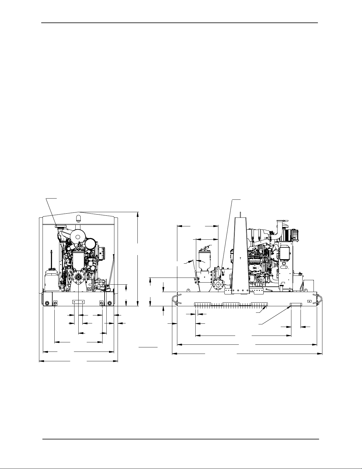
OUTLINE DRAWING
SUCTION:
6.00 NOMINAL WITH 8 HOLES.88/[22,4] DIA
EQUALLY SPACEDON A 9.50/[241,3] DIA BC
POWERED BY: JOHN DEERE 4045H FT4 DIESEL ENGINE
79.50
[ 2019,3 ]
APPROX
configuration, and priming must be tailored to the
specific application. Since the pressure supplied
to the pump is critical to performance and safety,
be sure to limit the incoming pressure to 50% of the
maximum permissible operating pressure as
shown on the pump performance curve.
For further assistance, contact your Gorman‐Rupp
distributor or the Gorman‐Rupp Company.
Pump Dimensions
See Figure 1 for the approximate physical dimen
sions of this pump.
DISCHARGE:
4.00 NOMINAL WITH 8 HOLES
.75/[19,0] DIA EQUALLY SPACED
ON A 7.50/[190,5] DIA BC
34.80
[ 884,0 ]
18.74
[ 475,9 ]
APPROX
24.01
3.38
[ 85,7 ]
[ 609,7 ]
APPROX
DIMENSIONS:
INCHES
[MILLIMETERS]
12.00
[ 304,8 ]
3.52
[ 89,3 ]
7.00
[ 177,8 ]
60.00
[ 1524,0 ]
40.50
[ 1028,8 ]
66.75
[ 1695,4 ]
23.92
[ 607,5 ]
18.12
[ 460,2 ]
9.75
[ 247,6 ]
Figure 1. Pump Model PA4B60-4045H FT4
PREINSTALLATION INSPECTION
The pump assembly was inspected and tested be
fore shipment from the factory. Before installation,
inspect the pump for damage which may have oc
curred during shipment. Check as follows:
10°
.69/[17,5] DIA
TYP
62 HOLES
.69/[17,5] X 1.19/[30,2]
2 SLOTS EACH SIDE
APPROX
81.00
[ 2057,5 ]
118.50
[ 3009,9 ]
8.00
[ 203,2 ]
15.62
[ 396,7 ]
2.00
[ 50,8 ]
127.00
[ 3225,8 ]
a. Inspect the pump for cracks, dents, damaged
threads, and other obvious damage.
b. Check for and tighten loose attaching hard
ware. Since gaskets tend to shrink after dry
ing, check for loose hardware at mating sur
faces.
PAGE B - 1INSTALLATION
OM-07183 PA SERIES
c. Carefully read all tags, decals, and markings
on the pump assembly, and perform all duties
indicated. Note that the pump shaft rotates in
the required direction.
Only operate this pump in the direction in
dicated by the arrow on the pump body
and on the accompanying decal. Other
wise, the impeller could become loosened
from the shaft and seriously damage the
pump.
d. Check levels and lubricate as necessary. Re
fer to LUBRICATION in the Maintenance and
Repair Manual and perform duties as in
structed.
e. If the pump has been stored for more than 12
months, some of the components or lubri
cants may have exceeded their maximum
shelf life. These must be inspected or re
placed to ensure maximum pump service.
If the maximum shelf life has been exceeded, or if
anything appears to be abnormal, contact your
Gorman‐Rupp distributor or the factory to deter
mine the repair or updating policy. Do not put the
pump into service until appropriate action has
been taken.
POSITIONING PUMP
Lifting
Death or serious personal injury and
damage to the pump or components
can occur if proper lifting procedures
are not observed. Make certain that
hoists, chains, slings or cables are in
good working condition and of suffi
cient capacity and that they are posi
tioned so that loads will be balanced
and the pump or components will not be
damaged when lifting. Suction and dis
charge hoses and piping must be re
moved from the pump before lifting. Lift
the pump or component only as high as
necessary and keep personnel away
from suspended objects.
Pump unit weights will vary depending on the
mounting and drive provided. Check the shipping
tag on the unit packaging for the actual weight, and
use lifting equipment with appropriate capacity.
Drain the pump and remove all customer‐installed
equipment such as suction and discharge hoses
or piping before attempting to lift existing, installed
units.
Battery Installation
The pump assembly can be seriously
Unless otherwise specified on the pump order, the
engine battery is not included with engine driven
units.
Refer to the information accompanying the battery
and/or electrolyte solution for activation and charg
ing instructions.
Before installing the battery, clean the positive and
negative cable connectors, and the battery termi
nals. Secure the battery by tightening the
holddown brackets. The terminals and clamps
may be coated with petroleum jelly to retard corro
sion. Connect and tighten the positive cable first,
then the negative cable.
PAGE B - 2 INSTALLATION
damaged if the chains or cables used to lift
and move the unit are improperly wrapped
around the pump.
Mounting
Locate the pump in an accessible place as close as
practical to the liquid being pumped. Level mount
ing is essential for proper operation. The pump
may have to be supported or shimmed to provide
for level operation and eliminate vibration.
For engine driven units, the pump must be posi
tioned as level as possible to ensure sufficient lubri
cation and fuel supply to the engine.

PA SERIES OM-07183
If the pump has been mounted on a moveable
base, make certain the base is stationary by setting
the brake and blocking the wheels before attempt
ing to operate the pump.
If the pump has been mounted on a mov
able base, do not attempt to operate the
pump unless the unit is level. Be sure
the leveling stands are positioned on a
solid surface, and the wheels are
chocked.
SUCTION AND DISCHARGE PIPING
Pump performance is adversely effected by in
creased suction lift, discharge elevation, and fric
tion losses. See the performance curve and oper
ating range shown on Page E‐1 to be sure your
overall application allows pump to operate within
the safe operation range.
Materials
Either pipe or hose maybe used for suction and
discharge lines; however, the materials must be
compatible with the liquid being pumped. If hose is
used in suction lines, it must be the rigid‐wall, rein
forced type to prevent collapse under suction. Us
ing piping couplings in suction lines is not recom
mended.
Line Configuration
Keep suction and discharge lines as straight as
possible to minimize friction losses. Make mini
mum use of elbows and fittings, which substan
tially increase friction loss. If elbows are necessary,
use the long‐radius type to minimize friction loss.
Connections to Pump
Lines near the pump must be independently sup
ported to avoid strain on the pump which could
cause excessive vibration, decreased bearing life,
and increased shaft and seal wear. If hose‐type
lines are used, they should have adequate support
to secure them when filled with liquid and under
pressure.
Gauges
The pump is drilled and tapped for installing dis
charge pressure and vacuum suction gauges. It is
recommended that gauges be installed to monitor
pump performance. Seal the gauge threads with
pipe dope to ensure an airtight seal. Follow the
sealant manufacturer's recommendations when
selecting and applying the pipe dope. The pipe
dope should be compatible with the liquid being
pumped.
SUCTION LINES
To avoid air pockets which could affect pump prim
ing, the suction line must be as short and direct as
possible. When operation involves a suction lift, the
line must always slope upward to the pump from
the source of the liquid being pumped; if the line
slopes down to the pump at any point along the
suction run, air pockets will be created.
Fittings
Suction lines should be the same size as the pump
inlet. If reducers are used in suction lines, they
should be the eccentric type, and should be in
stalled with the flat part of the reducers uppermost
to avoid creating air pockets. Valves are not nor
mally used in suction lines, but if a valve is used,
install it with the stem horizontal to avoid air pock
ets.
Strainers
Be certain to use the strainer furnished with the
pump; any spherical solids which pass through the
strainer will also pass through the pump itself.
Before tightening a connecting flange, align it ex
actly with the pump port. Never pull a pipe line into
place by tightening the flange bolts and/or cou
plings.
If a strainer not furnished with the pump is installed
by the pump user, make certain that the total area
of the openings in the strainer is at least three or
four times the cross section of the suction line, and
PAGE B - 3INSTALLATION

OM-07183 PA SERIES
that the openings will not permit passage of solids
larger than the solids handling capability of the
pump.
This pump is designed to handle up to 3 inch (76,2
mm) diameter spherical solids.
Sealing
Since even a slight leak will affect priming, head,
and capacity, especially when operating with a
high suction lift, all connections in the suction line
should be sealed with pipe dope to ensure an air
tight seal. Follow the sealant manufacturer's rec
ommendations when selecting and applying the
pipe dope. The pipe dope should be compatible
with the liquid being pumped.
Suction Lines In Sumps
If a single suction line is installed in a sump, it
should be positioned away from the wall of the
sump at a distance equal to 1 1/2 times the diame
ter of the suction line.
suction inlet at a distance 1‐1/2 times the diameter
of the suction pipe. The baffle will allow entrained
air to escape from the liquid before it is drawn into
the suction inlet.
If two suction lines are installed in a single sump,
the flow paths may interact, reducing the efficiency
of one or both pumps. To avoid this, position the
suction inlets so that they are separated by a dis
tance equal to at least 3 times the diameter of the
suction pipe.
Suction Line Positioning
The depth of submergence of the suction line is
critical to efficient pump operation. Figure 2
shows recommended minimum submergence vs.
velocity.
Although not recommended, the vacuum assisted
priming feature allows the pump to be operated
temporarily in a “slurping” application with varying
water levels.
If there is a liquid flow from an open pipe into the
sump, the flow should be kept away from the suc
tion inlet because the inflow will carry air down into
the sump, and air entering the suction line will re
duce pump efficiency.
If it is necessary to position inflow close to the suc
tion inlet, install a baffle between the inflow and the
NOTE
The pipe submergence required may be reduced
by installing a standard pipe increaser fitting at the
end of the suction line. The larger opening size will
reduce the inlet velocity. Calculate the required
submergence using the following formula based
on the increased opening size (area or diameter).
PAGE B - 4 INSTALLATION
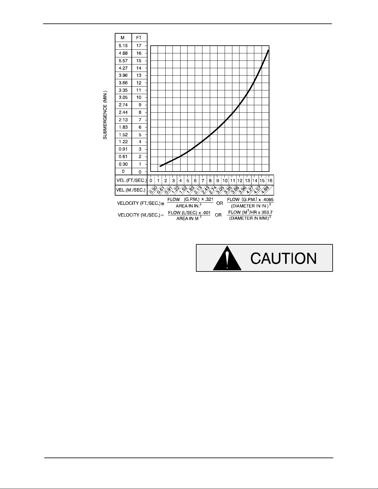
PA SERIES OM-07183
Figure 2. Recommended Minimum Suction Line Submergence vs. Velocity
DISCHARGE LINES
Siphoning
Do not terminate the discharge line at a level lower
than that of the liquid being pumped unless a si
phon breaker is used in the line. Otherwise, a si
phoning action causing damage to the pump
could result.
Valves
This pump is designed with a check valve in the
discharge line.
If a throttling valve is desired in the discharge line,
use a valve as large as the largest pipe to minimize
friction losses. Never install a throttling valve in a
suction line.
With high discharge heads, it is recommended that
a throttling valve be installed in the discharge line
to protect the pump from excessive shock pres
sure and reverse rotation when it is stopped.
If the application involves a high discharge
head, gradually close the discharge
throttling valve before stopping the pump.
ALIGNMENT
The alignment of the pump, air compressor and
engine is critical for trouble‐free mechanical opera
tion. See Section E, Securing Intermediate And
Drive Assembly To Engine in MAINTENANCE
AND REPAIR, for details.
AUTO‐START
The standard pump is equipped with an auto‐start
control system which allows the pump to start and
stop as the liquid level in the wet well or sump rises
and falls.
Refer to the information which follows for installa
tion details for the liquid level sensing system pro
vided with your pump.
PAGE B - 5INSTALLATION
OM-07183 PA SERIES
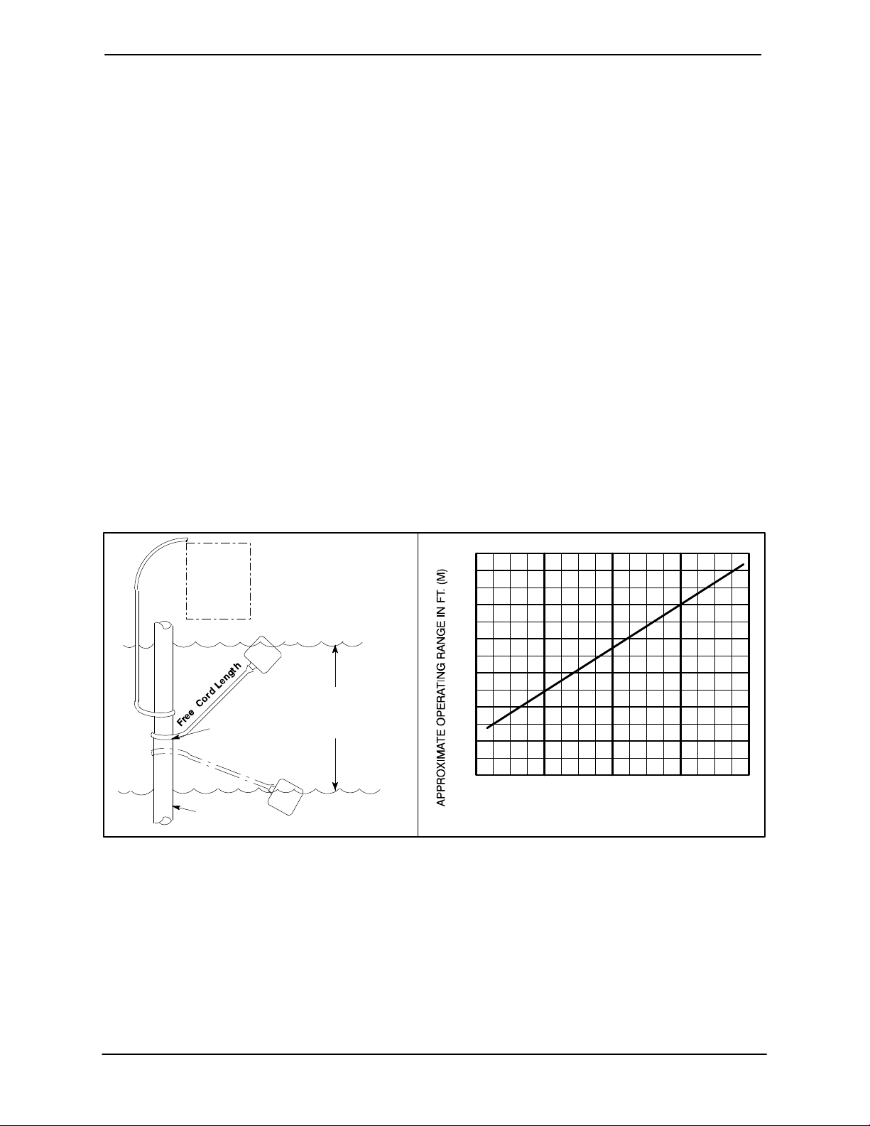
Float Switch Installation
The Float Switch autostart system employs either a
single or double float switch, where a bulb raises or
lowers (floats) with the liquid level, thus activating
an enclosed miniature switch. The floats are
equipped with a socket type connector that plugs
into a matching receptacle on the auto‐start control
box.
Standard floats are equipped with 50 feet (15,2 m)
of cable.
When installing the floats, note the following:
a. Be sure to provide sufficient room in the wet
well or sump so that floats do not get ob
structed or drawn into the suction line. If a flex
ible suction hose is used, it may be extended
to lay along the bottom of the wet well or sump
and the float can be attached to the hose
above the point where it bends along the bot
tom. Direct the suction line toward the flow,
and the float(s) away from the flow. If a stand
pipe is available, attach the float switch cable
to the standpipe in the sump at the approxi
mate desired liquid level.
b. In a single float system, the cable can be teth
ered to the suction line or standpipe approxi
mately 6 inches (152 mm) above the float.
This setting allows approximately 9 inches
(229 mm) of liquid rise between pump start/
stop. The start/stop interval may be increased
by extending the float end of the cable. The
liquid level in the sump will increase approxi
mately 8 inches (203 mm) between start/stop
intervals for every 6 inches (152 mm) of cable
increase.
c. If a double float switch system is used, posi
tion the “Start” float at the desired high water
level in the sump, and the “Stop” float at the
desired low water level in the pump.
d. Refer to Figure 3 for additional float switch
data.
ENGINE
CONTROL
BOX
ON
(Emptying)
OFF
(Filling)
OPERATING
CABLE
TETHER
RANGE
(See Table Below)
POINT
OFF
(Emptying)
1.25” Pipe
(Not Furnished)
ON
(Filling)
Figure 3. Float Switch Data
COLD WEATHER INSTALLATION
If the pump is to be installed in an environment
where sub‐freezing temperatures will occur during
operation, consideration must be given to prevent
the pump and components from freezing when the
pump is idle between pumping cycles. With Gor
man‐Rupp priming assisted pumps, there are two
methods of accomplishing this.
3.0
(0.9)
2.5
(.76)
2.0
(0.6)
1.5
(.46)
1.0
(0.3)
0.5
(.15)
1.0
(0.3)
APPROXIMATE FREE CORD LENGTH IN FT. (M)
2.0
(0.6)
3.0
(0.9)
4.0
(1.2)
One method is through the use of an optional heat
ed priming chamber, which is available as a facto
ry‐installed option or as a retrofit kit for most mod
els (consult the factory). This method pumps heat
ed liquid from the engine cooling system through
the priming chamber to heat the chamber and its
contents. This method is particularly effective
where pumping cycles are short enough to ensure
PAGE B - 6 INSTALLATION

PA SERIES OM-07183
that the liquid in the priming chamber never fully
freezes.
The second method involves configuring the
pumping system to drain both the priming cham
ber and pump casing after each pumping cycle.
With no liquid remaining in the system, freezing
cannot occur.
To configure the pump to drain between pumping
cycles, the first step is to remove the check valve
from the line that runs between the top of the prim
ing hopper and the priming venturi. This check
valve is located close to the venturi end of the line.
Remove the check valve, then reconnect the line
directly to the venturi. This will allow air to enter the
pump through the top of the priming hopper when
the pump shuts off, providing for complete
drainage of the pump and priming hopper.
Next, install a drain line between the pump drain
and the wet well or sump. This line must remain
submerged in the liquid below the pump down lev
el of the liquid level control device; otherwise, the
pump may not prime. If the application involves liq
uids that could clog the drain line, make sure to
check the line periodically to ensure it remains
open; otherwise, liquid could remain in the casing,
resulting in freezing and potential damage to the
pumping system.
Configuring the system to drain between cycles
will help ensure that the pump will not freeze during
cold weather applications. However, it should be
noted that the time required for the pump to be
gin to discharge liquid will increase, as the
pump will have to fully re‐prime at the beginning
of each pumping cycle.
PAGE B - 7INSTALLATION
PA SERIES
OM-07183
OPERATION - SECTION C
Review all SAFETY information in Section A.
Follow the instructions on all tags, labels and
decals attached to the pump.
Do not operate an internal combustion
engine in an explosive atmosphere.
When operating an internal combustion
engine in an enclosed area, make sure
exhaust fumes are piped to the outside.
These fumes contain carbon monoxide,
a deadly gas that is colorless, tasteless
and odorless.
OPERATION
cated (see LUBRICATION in MAINTENANCE
AND REPAIR).
The pump will begin to prime upon startup. The air
in the suction line will be discharged from the educ
tor discharge line. Complete priming is indicated
by a positive discharge pressure reading.
If full priming is not achieved, the discharge check
valve may be malfunctioning. If this occurs, shut
down the pump and consult Maintenance and
Repair, Section E for further details.
STARTING
Check the fuel level and oil levels in the engine, air
compressor, pump bearings and seal housing.
Make sure the pump is level. Lower the jack stands
and chock the wheels, if so equipped.
This pump is designed to handle most
non‐volatile, non‐flammable liquids
containing specified entrained solids
and corrosives. Do not attempt to pump
volatile, corrosive, or flammable liquids
which may damage the pump or endan
ger personnel as a result of pump fail
ure.
Pump speed and operating condition
points must be within the continuous per
formance range shown on the perfor
mance curve in Section E on page E-1.
PRIMING
Install the pump and piping as described in IN
STALLATION. Make sure that the piping connec
tions are tight, and that the pump is securely
mounted. Check that the pump is properly lubri
Make sure the pump is level. Lower jack
stands and chock the wheels, if so
equipped. Use caution when positioning
the skid‐mounted unit to prevent damage
to the fuel tank.
This pump is equipped with an automat
ic starting system, and is subject to au
tomatic restart. Keep hands and cloth
ing away from the unit to prevent injury
during automatic operation. Disconnect
the positive battery cable before per
forming any maintenance. Failure to do
so may result in serious personal injury.
Consult the engine operations manual before at
tempting to start the unit.
Manual Starting
On initial start‐up, set the engine speed at in the
half‐throttle position. Turn the keyswitch to `MANU
OPERATION PAGE C - 1
 Loading...