


RADIO MANUFACTURER
43-200 Pszczyna, Staromiejska 31b
tel. 032 326 30 70, www.gorke.com.pl
4-channel identification receiver
type
>>> IDO-1000 <<<
> v1.12 <
Operating manual
Version 1.00

RADIO MANUFACTURER
43-200 Pszczyna, ul. Staromiejska 31b
tel. 032 326 30 70, www.gorke.com.pl
1. Table of contents
1. Table of contents ... ...................................................................................................................... 2
2. IDO-1000 receiver characteristics............................................................................................... 3
2.1. Field of application ... ........................................................................................................... 3
2.2. IDO-1000 receiver basic features ... .................................................................................... 3
2.3. Short operation description ... .............................................................................................. 3
3. Relays and their working modes... .............................................................................................. 4
3.1. Relays... ................................................................................................................................ 4
3.2. Relays' working modes... ..................................................................................................... 4
3.3. Working times and delays... ................................................................................................. 6
3.4. Clock events ... ..................................................................................................................... 6
4. Operation ... ................................................................................................................................. 7
4.1. Main menu ... ........................................................................................................................ 7
4.1.1. Relay learning - Nauka nad [Relay learn.]... ............................................................... 7
4.1.2. Relay reset - Kasowanie nad [Relay reset]... ............................................................ 7
4.1.3. Program selection - Wybor scenar. [Program sel.] .. ................................................ 7
4.1.4. Events log - Historia zd.[Events log].. ....................................................................... 7
4.1.5. Other options - Pozostale [Other opt.]... ....................................................................... 8
4.1.5.6. Relay learning with place selection ... ....................................................................... 8
4.1.5.7. Events selection-based sending ... ............................................................................. 8
5. Interaction with computer and printer ... ..................................................................................... 8
6. Display options... ......................................................................................................................... 8
7. Advanced options ... .................................................................................................................... 9
8. Technical data ... ...................................................................................................................... . 10
9. IDO-1000 Configuration program……………….……………………………..11-14 (2nd part)
External document
2
IDO-1000 Identification Receiver instruction manual and specification

RADIO MANUFACTURER
43-200 Pszczyna, ul. Staromiejska 31b
tel. 032 326 30 70, www.gorke.com.pl
2. IDO-1000 receiver characteristics
2.1. Field of application
Common fields of application of IDO-1000 receiver are as follows:
- entrance gates and exit gates of buildings and estates,
- user identification systems connected with switching-on and switching-off of various actuators,
signaling devices, gates, engines, etc.,
- devices remote control systems.
2.2. IDO-1000 receiver basic features
- memory up to 1000 transmitters (remote controls)
- memory up to 1024 events (presses)
- information about transmitters (26 chars) shown on the display
- separate resetting of transmitters from the relay's memory
- low battery alert
- improper amount of „ presses” al ert (for ins tance hacking attem pt by me ans of an
intercepted code)
- selec t ion of on e of 4 r elay wo rki ng pr ogra ms for each remote control
- full Keeloq system operation (manufactured by Microchip)
with a so-called rolling code
- clock events (alerts) triggered off when the real-time clock reaches a given date and hour
- direct or alternating current supply (9-24V)
- built-in an tenna or D ig ita l Line Amplifier connect ion ( jum per op tio nal)
- PC joint connec tion ( RS 232 ca ble inc luded)
2.3. Short operation description
Having connected IDO-1000 to a power source, the device undertakes the autotest
procedure. It will inform the user in case of a critical error
. If the test is considered positive, the
display will show information concerning software version.
>>> IDO-1000 <<<
> v1.10 <
Several seconds later it displays a clock (or other notice).
From this very moment the receiver reaches the state of watch. If any Keeloq system transmitter
was used in its vicinity, IDO-1000 shifts into data frame decoding.
The frame sent by the transmitter comprises of, among others, serial number of the transmitter,
number of the pressed button (key) and a press-o-meter.
IDO-1000 searches in the transmitter's memory of an appropriate serial number and checks the
press-o-meter. In case of finding one, IDO-1000:
- initiates a proper program associated with relay operation, depending on the pressed button,
- information concerning the transmitter are shown on the display
- transfers infor mation concerning the transmitter on RS232 port.
External document
3
IDO-1000 Identification Receiver instruction manual and specification

RADIO MANUFACTURER
43-200 Pszczyna, ul. Staromiejska 31b
tel. 032 326 30 70, www.gorke.com.pl
A model operation:
NAD-0002/03!BAT!
Jan Kowalski ul.
The display shows information about the transmitter's number (0002) and the button used (03).
What is more, it has low battery (!BAT!)
The transmitter's name is winding below its number (Jan Kowalski ul. Cicha 102).
An example of pr int ou t cre ated dur ing IDO-1000 operation is presented below:
2009-06-03 15:11:45 NAD-0002/02 ----- Jan Kowalski ul. Cicha 102
2009-06-03 15:11:49 NAD-0001/05 ----- Ireneusz Nowak ul.Prosta 3
2009-06-03 15:11:50 NAD-0002/02 ----- Jan Kowalski ul. Cicha 102
2009-06-03 15:11:53 NAD-0007/01 !BAT! Piotr Wysoki ul.Kreta 33/1
2009-06-03 15:11:54 NAD-0007/01 !BAT! Piotr Wysoki ul .Kreta 33/1
2009-06-03 15:11:56 NAD-0002/02 ----- Jan Kowalski ul. Cicha 102
2009-06-03 15:11:56 NAD-0001/06 ----- Ireneusz Nowak ul.Prosta 3
2009-06-03 15:12:00 NAD-0002/02 ----- Jan Kowalski ul. Cicha 102
It can be seen that transmitter 0007 has low battery that needs exchanging.
When no transmitter is found in the memory, IDO-1000 reacts by a short sound and animation
seen in the top right corner of the display.
3. Relays and their wo rking modes
3.1. Relays
IDO-1000 possesses 4 relays of 10A c ontact rating.
Only joints NO (Normally Open), C (Common), NC (Normally Closed) are connected with the
terminal block.
The relay is considered as wor king when a diode ov er it is on.
When it is working, NO joint is shortened with C joint and NC joint is shortened with C joint.
3.2. Relays' wo r king modes
Every relay may work in any of the following modes. The way which relay works in which mode
depends on: firstl y, on the program ascribed to a giv en relay; secondly, on the button used in a given
relay.
External document
4
IDO-1000 Identification Receiver instruction manual and specification

RADIO MANUFACTURER
43-200 Pszczyna, ul. Staromiejska 31b
tel. 032 326 30 70, www.gorke.com.pl
The available relay working modes are presented below:
No. Mode Abbrev. Description Work in g time Delay Applications
1 monostable M__
the relay is switched on on a
given period of time
optional: timer0,
timer1, timer2,
timer3
n/a
- entrance gate operation (for instance
joints shortage for 2 seconds)
2
monostable
delayed
Mo_
the relay is switched on on a
given period of time after a
given delay time
optional: timer0,
timer1, timer2,
timer3
optional: delay0,
delay1, delay 2,
delay3
- ope ning of subseque nt do or a fter a given
period of time
3
monostable
with early
reset
M_k
the relay is sw it che d o n on
a given period of time and
the button's reuse causes the
relay's switch-off
optional:timer0,
timer1, timer2,
timer3
n/a
- switching-on the light (for instance for
night-time) with e arl ier sw itc h-off
possibility
4
monostable
delaye d w ith
early reset
Mok
the relay is tur ne d on o n a
given period of time and the
button's reuse causes the
relay's turn-off
optional: timer0,
timer1, timer2,
timer3
optional: delay0,
delay1, delay2,
delay3
-
designing lighting „tracing ” the use r w it h
early sw itch-off option
5
bistable
B__
the relay is sw it che d in to
opposite sta te
n/a
optional: delay0,
delay1, delay 2,
delay3
- opposite state necessity control (mixing
unit)
6
bistable
delayed
Bo_
the relay is sw it che d in to
opposite sta te af ter a g ive n
period of time (delay)
n/a
optional: delay0,
delay1, delay 2,
delay3
- opposite state necessity control (mixing
unit)
7
turn-on
Z__
the relay is tur ne d on
permanently after a given
period of time (until another
mode is activated or there is
no supply voltage)
n/a n/a - lighting control
8
delaye d tur n-
on
Zo_
the relay is tur ne d on
permanently after a given
period of time (until another
mode is activated or there is
no supply voltage)
n/a
optional: delay0,
delay1, delay 2,
delay3
- night lighting control
9
switch-off
W__
the relay is sw it che d of f
permanently after a given
period of time (until another
mode is activated)
n/a n/a - lighting control
10
delayed
switch-off
Wo_
the relay is sw it che d o f f
permanently after a given
period of time (until another
mode is activated)
n/a
optional: delay0,
delay1, delay 2,
delay3
- night lighting control
11
temporary
C__
the relay is tur ne d on as l o ng
as the transmit ter's butto n is
pressed.
n/a n/a - control depends on the stroke time
12
no action
___
no relay state change n/a n/a
External document
5
IDO-1000 Identification Receiver instruction manual and specification

RADIO MANUFACTURER
43-200 Pszczyna, ul. Staromiejska 31b
tel. 032 326 30 70, www.gorke.com.pl
3.3. Working times and delays
In case of the monostable modes, the selection of one of four timers countin g down the relays'
working time is possible (each of them is set within the range of 0-24h with 0,1s step).
In case of the delayed ones the selection of one of four t imers c oun ting down the time nec essary to
the program's sta r t ( ea ch o f th em is se t w it h in the range of 0-24h with 0,1s step) .
3.4. Clock events
Up to four so-called clock events can be configured within IDO-1000 receiver, e.g. events
occurring when the real-time clock (RTC) reaches a given date and hour. The clock events are
assigned to t ransmi tt ers 100 1-100 4 and t reat ed so as a com mon t ransm itt er woul d hav e been used
(all relay working modes are available). This feature allows to control the relays automatically on
specific hours.
What is more, a „no-matter” digit can be assigned when date/hour is being described. It enables
the clock events to be triggered off in a cyclical pattern.
Example 1:
We want to use IDO-1000 to turn off the lights on th e staircase.
W e set the date/hour of this event on:
20**-**-** 23:00:00 - what causes that the clock event will be done everyday
at 23:00:00 in the years: 2000-2099.
Example 2:
In July (when we are on h oliday ) we automatically switch the aquarium filter on.
We set the clock event:
20**-07-** 15:00:15 it will be done in July at 15:00:15.
Example 3:
In December, from 19:00 to 21:00, we want to switch the information board on and off consecutively.
We employ here two clock events:
The first clock event is designed to control the relay from 19:00:00 to 19:59:59
20**-12-** 19:**:**
The second clock event is designed t o c ontrol the relay from 20:00:00 to 20:59:59
20**-12-** 20:**:**
In both cases we use the same button and program number which should be
programm ed as bistable
. It will be do ne e very sec ond fro m 19 to 21.
External document
6
IDO-1000 Identification Receiver instruction manual and specification

PRODUCENT URZĄDZEŃ RADIOWYCH
43-200 Pszczyna, ul. Staromiejska 31b
tel. 032 326 30 70, www.gorke.com.pl
4. Operation
IDO-1000 is controlled by means of NO, -, +, YES buttons:
- the YES button serves as an entry to the menu and its submenus, as well as an acceptance of the
selections made,
- the NO button serves as an exit from the menu and its submenus, as well as cancelation means
of all selections and operations,
- the „-„ i „+” buttons help choose an option from the menu, as well as change various
parameters.
4.1. Main menu - available after pr essing any button.
4.1.1. Relay learning -
Nauka nad. [Relay learn.]
Allows to program remote controls (transmitters) to IDO-1000 memory. Having found a free
space in the memory, IDO-1000 requests for pres si n g the trans mi tter being implemented two times.
4.1.2. Relay reset -
Kasowanie nad. [Relay reset]
We choose th e desired transmitter to be res et by means of +/- buttons and accept the choice b y
pressing the „YES” button. When the remote control number is displayed, the * mark means
that the memory is full (remote control programmed in compliance with IDO-1000).
4.1.3. Program selection -
Wybor scenar. [Program sel.]
Allows to choose the relay working program assigned to a given remote control. The first thing to
do is to choose a transmitter and then the program should be selected, which will be activated by
means of this transmitte r.
4.1.4. Events log -
Historia zd. [Events log]
Allows to browse events in the receiver's memory.
The event can be selected by +/- buttons. The display shows: on the left date and hour of the
event, on the right its nu m ber, on the bottom the remote co ntro l' s and b ut ton' s nu mber.
09-05-28 ab12 B!
11:53:20 0002/02
'B' and '!' symbols may be seen in the top right corner of the display - they mean low battery and
inadequate value of the press-o-meter (more details can be viewed in the section for advanced users).
External document
7
IDO-1000 Identification Receiver instruction manual and specification

RADIO MANUFACTURER
43-200 Pszczyna, ul. Staromiejska 31b
tel. 032 326 30 70, www.gorke.com.pl
4.1.5. Other options -
Pozostale [Other opt.]
4.1.5.6. Relay learning with place selection Nauka nad. z wyborem
[Relay learn. with place sel.]
Allows to selec t such memory space, within which the transm itte r wi ll be pr og ra mmed.
4.1.5.7. Events selection-based sending
Wysylanie zd. z wyborem [Events
sel.-based send.]
Allows to choose the firs t a nd the las t eve nt in the m e mory and transfer it to a computer or a printer.
5. Interaction with computer and printer
IDO-1000 has a built-in RS232 port (described on the circuit board as PC) enabling to connect it
to a PC computer. In order to use IDO-1000 in full, it is necessary to operate a computer with
software installed from the disc included in the unit.
It is also possible to connect IDO-1000 to any serial printer (for instance a thermal one, KAFKA
type). The printer will be constantly printing date, hours, numbers and names of th e transmitters
received. It is feasible to transfer the IDO-1000 events log to a printer or computer, too.
6. Display options
IDO-1000 can be set so as the display in the standby mode will show:
• current time,
• current date and time (displayed conseq uently)
• the transmitter recently turned on
• notice implemented by the user
External document
8
IDO-1000 Identification Receiver instruction manual and specification

RADIO MANUFACTURER
43-200 Pszczyna, ul. Staromiejska 31b
tel. 032 326 30 70, www.gorke.com.pl
7. Advanced options
The transmitter in the Keeloq® system sends information about the battery condition. If IDO1000 receives such information, that the transmitter has low battery, the display and the printer (or
computer) will show !BAT! notice. Even in the events log, along with the event number, a 'B'
letter appears meaning that the given device has low battery.
In the Keeloq® system the transmitter also sends a coded, internal press-o-meter reading, which
is being increased of 1 per 1 button stroke.
IDO-1000 checks, if any incoming information from the transmitter possesses an appropriate
press-o-meter reading.
The possible situations are as follows:
•
the press-o-m e ter reading sending by th e transmitter is 1 higher th an the previously
remembered one - an usual situation;
•
the press-o-meter reading is higher not more than 16 than the previously put
down one - an usual situation but the user wasted his/her time on the device;
the Keeloq® system allows to press the transmitter button 16 times wit h no
consequences taken;
• the press-o-meter reading is higher more than 16 than the previously saved one,
but not more than 32768 - then ID O -1000 switches into the press-o-meter re synchronization state; in such a situation the first use of the transmitter is of no
effect, only the second one causes the meter to be updated in the memory and the
relays to be turned on; the display shows !SCN! symbol next to the transmitter
number;
• the press-o-meter reading is lower or higher more than 32768 from the memory
state; in such a case IDO-1000 claims that the remote control to be damaged, false
readings occurred during the transmission or a person tries to act as a transmitter;
then the information regarding the transmitter will be written in the IDO-1000
memory but the transmitters will undertake no program; the display shows !LNA!
symbol, whereas along the event number in the e ve nt l og a ' ! ' will appear.
It should be remem b ered that the press-o-meter's reading sending by the transmitter is coded and
any „forgery” of its factual value is impossible. Taking this into account, the probability of
choosing a proper code is lower than 1 to 7,38 x 10¹⁹ (according to the Microchip records).
IDO-1000 receiver interacts with any Gorke Electronic transmitter (except for NRP-102K).
Workin g ranges, de pending on th e transmit ter's type, amount up fr om 200 to 1000 m eters (appl y
to open space, when the transmitter and receiver „see each other”).
External document
IDO-1000 Identification Receiver instruction manual and specification

RADIO MANUFACTURER
43-200 Pszczyna, ul. Staromiejska 31b
tel. 032 326 30 70, www.gorke.com.pl
8. Technical data
Power supply:
Supply voltage: 9-24V of alternating/direct current
Current input in standby mode: 0.09A (Uzas=9V), 0.05A(12V), 0.03A(24V)
Maximum current input: 0.34A (Uzas=9V), 0.24A(12V), 0.12A(24V)
Radio part:
Superheterodyne rece iver
Frequency: 433MHz
sensitivity: -115dBm
aerial cell: BNC, 50Ω
aerial: rod 1/4λ provided
or
WLC receiver (not included in the unit)
Receiver standard:
Relays
Number:
Contact rating :
T ransmitter m emory:
Transmit te r d esc r ip t ion :
Events log:
Display:
Char type:
Backlight
Contrast:
Clock
Keeloq ® produced by Microchip
Keeloq ® produced by Microchip
4
10A/277V AC
12A/125V AC
1000 transmitters
maximum 26 chars
1024 events
2 lines, 16 chars each
LED, PWM-controlled
regulated by means of a potentiometer
Real-time clock with calendar
Battery-supplied
Battery type: CR1220
Clock events (alarms)
Number 4
Assigned transmitter num ber 1001-1004
Timers
Monostable mode regulati on 0-23:59:59 with 0.1s ste p
range
Delay regulation range 0-23:59:59 with 0.1s ste p
The timers are not synchronized with the real-time clocks.
Others
T amp er joint ( SAB) : opened during the casing's opening
sound signaling device
External document
IDO-1000 Identification Receiver instruction manual and specification

RADIO MANUFACTURER
43-200 Pszczyna, ul. Staromiejska 31b
tel. 032 326 30 70, www.gorke.com.pl
IDO-1000 Configuration program (v1.12)
Delivered along with IDO-1000 receiver, it allows to its full use and enables:
- naming the transmitters (or remote controls),
- checking the IDO-1000 memory condition,
- selecting program of the assigned transmitter,
- creating working relay programs,
- configuring relay working times and
delays, - selection of infor mation shown on
the IDO-1000 display,
- configuring clock events,
- resetting all IDO-1000 m emory,
- receiving events from IDO-1000.
IDO-1000 Configuration program operation
In order to connect IDO -1000 to a computer with IDO-1000 Configur ation program, the cable included in the
unit should be used. It should be inserted into a free COM co mputer port from one side a nd to „PC” joint on the IDO1000 circuit board from the second. The plug has an appropriate notch allowing to put the cable correctly into.
Then the IDO-1000 Co nfiguration program should be star ted and the serial port should be chosen, t hrough which
the communication with IDO-1000 will be made.
The program comprises of a row of bookmarks, in connection with which the receiver's parameters should be configured.
All IDO-1000 settings can be fully deciphered (by the „READ ALL SETTINGS FROM IDO-1000 ” button) and la ter
edited or, on the subsequent bookmarks, re-deciphered, amended an d sav ed into IDO-1000.
These settings can also be saved to IDO-1000 (by the „ SAVE ALL SETTINGS TO IDO-1000” button).
„REMOTE CONTROLS” bookmark
It allows to assign names to remote controls and preview the IDO-1000 memory contents.
The bookmark's central pla ce is occupied by a sheet disp laying the IDO -1000 memory state. Eve ry progra mmed
remote control (transmitter) is symbolized by „#” mark.
Clicking on a given place on the sheet we select a proper transmitter and it may be named and has the program set in
case when the signal w i ll be rec ei ved.
Edition of individual transmitters is also possible. In order to do that, buttons „READ A GIVEN REMOTE
CONTROL FROM IDO-1000” and „SAVE THE SELECTED REMOTE CONTROL TO IDO-1000” butt ons. It
allows to edit the transmitter quickly without reading all IDO-1000 memory (it usually lasts around a minute).
It can be seen that in this receiver 6 transmitters a r e
programmed. The chosen one i no. 5. Its name is displayed in the
window below the sheet.
[Legend: PILOTY - Remote controls, SCENARIUSZE - Programs,
POZOSTAŁE
- Others, ZDARZENIA - Events, WYBIERZ PILOTA
- Select remote control, NAZWA PILOTA
- Choose a control,
ODCZYTAJ WYBRANY PILOT Z IDO-1000
- READ A GIVEN
REMOTE CONTROL FROM IDO-1000, ZAPISZ WYBRANY
PILOT DO IDO-1000 - SA VE THE SELECTED REMOTE
CONTROL T O IDO -1000]
External document
11
IDO-1000 Identification Receiver instruction manual and specification

RADIO MANUFACTURER
43-200 Pszczyna, ul. Staromiejska 31b
tel. 032 326 30 70, www.gorke.com.pl
„PROGRAMS” bookmark
Allows to manage the relays working programs.
4 independent ones can be chosen. Each of them reveals operation details of every relay depending on the
transmitter's pressed button together with their working times and delays.
Having clicked on the bookmark, a table
presenting the current relay mode for all
transmitters' buttons
is seen. Buttons from 1 to
14 and relays from 1 to 4 are available. Clic king
on the intersection between „RELAY”
(„PRZEKAŹNIK”) and „BUTTON”
(„PRZYCISK”) columns, there is a possibility of
selecting:
- program
- working time tim er (for monostable modes)
- delay tim er (for del ayed modes)
Having selected an appropriate button and relay, further configuration shall be made in the „WORKING MODE” („TRYB
DZIAŁANIA”) window.
We select the relay worki ng mode (that is its reaction on pressing a button) monostable, monostable dela yed, monostabled with reset, bistable, bistable
with reset, t urn-on, delayed turn-on, switch-off, delayed switch-off, temporary
and no action.
Below we choose timer (clock) counting down the relay working time (for
monostable modes).
Then (lower) we choose the delay with which the given mode will be
started (for delayed modes).
If for any chosen mode (monostable, for instance) the „delay” has no sense,
further options are unavailable.
Timers working times can be set in the table „TIMERS, DELAYS” („TIMERY,
OPÓŹNIENIA”). Choose TIMER0-3 and DELAY0-3.
Time can be set f rom 0.1s t o 23:59:59. 1s
Having adjusted all program parameters, they can be transfered to IDO-1000
by means of the „SAVE PROGRAMS TO IDO-1000” („ZAPISZ
SCENARIUSZE DO IDO-1000”) button - it should be remembered that the
current IDO-1000 settings will be overwritten.
The „DEFAULT CONFIGURATION” („USTAWIENIA DOMYŚLNE”) button triggers off loading of the most
common programs used in installations.
The systems' con figuration syste m (modes, times, dela ys selection) allo ws to unlimited r elay reactions a rrangement
by means of pres sing the transmitters' buttons. It should be remembered that loading of new relay working mode
causes inactivation of the old mode. For instance, when we set the monostable mode for a given relay, its working time
for an hour and we switch the relay on, and at the same time for the same relay we activate the bistable mode, the
monostable one will be deactivated. After an hour there will be NO relay switch-off. The monostable mode have been
substituted with the bistable one.
External document
12
IDO-1000 Identification Receiver instruction manual and specification

RADIO MANUFACTURER
43-200 Pszczyna, ul. Staromiejska 31b
tel. 032 326 30 70, www.gorke.com.pl
„OTHERS” bookmark
Allows to set the clock in ID O-1000 and the disp lay co ndition, as well as co nfigure t he clock e vents and fully
delete the receiver's memory.
In the „DISPLAY” („NA WYŚWIETLACZU”)
section we may implement a piece of information
which can be seen on the display in standb y mode.
W e can select:
- the clock,
- the clock and date alternately,
- the latest transmitter received and found in the
memory
- a notice set by the user (for instance a commercial
banner, tel ephon e n umber, etc.)
Using the „READ OUT OF IDO-1000” and
„SEND TO IDO-1000” („ODCZYTAJ Z IDO1000” i „WYŚLIJ DO IDO-1000”) buttons,
information concerning the display state may be
received from and sent to ID O-1000.
In the „CLOCK EVENTS” („ZDARZENIA
ZEGAROWE”) section we can configure all
events triggered off in the very moment of
reaching by the clock a given hour and date
.
Such events are described as transmitters 1001-1004. Any event may be determined by hour and date when it shall be
revealed with the possibility of entering the „*” mark, meaning any value of a given parameter. We define the button
and the program occ urring in the mome nt of reaching a given date and hour, set the event name and claim whether it
shall be active or not. Using the „READ OUT OF IDO-1000” and „SEND TO IDO-1000” (ODCZYTAJ Z IDO1000” i „WYŚLIJ DO IDO-1000”) buttons, we can quickly receive and send the settings to IDO-1000.
The clock events system enables (along with connecting relays parallel or in series) some processes to be automated.
For example, it can be arra nged that opening a gate will be possible only from 7: 00 to 20:00, that the light will be
automatically turned off or on, etc.
The „DELETE IDO-1000 MEMORY” („SKASUJ PAMIĘĆ IDO-1000”) button causes the IDO-1000 receiver's
memory to be completely deleted (both the transmitters' an d th e ev ent s' memory).
„EVENTS” bookmark
Allows to peek at events coming out of IDO-1000.
It shall be re membere d that ac tivating this function
blocks data receiving and sending on all other
bookmarks.
The „RECEIVE THE EVENTS LOG FROM
IDO-1000” („ODBIERZ HISTORIĘ ZDARZEŃ
Z IDO-1000”) button gets the events from the
receiver.
The „SAVE TO FILE” („ZAPISZ DO PLIKU”)
button allo ws to save a windo w's content to a text
file.
The „PRINT” („DRUKUJ”) butto n pri nt s a window's content on a default printer.
External document
13
IDO-1000 Identification Receiver instruction manual and specification
RADIO MANUFACTURER
43-200 Pszczyna, ul. Staromiejska 31b
tel. 032 326 30 70, www.gorke.com.pl
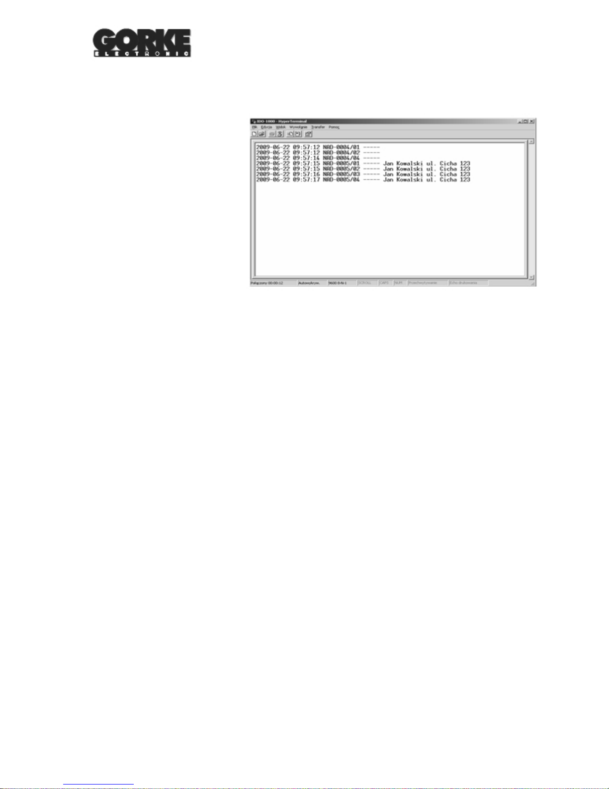
In order to receive the events from IDO-1000, any terminal program may be used, setting the connection parameters
as follows:
- speed 9600 bits/sec
- word count: 8 bits
- parity: no
- stop bits: 1
9600/8N1 in brief.
An example of events reception from
IDO-1000, by means of the Hyper
Terminal program (in Windows OS), is
presented on the right.
External document
14
IDO-1000 Identification Receiver instruction manual and specification
 Loading...