

Page 1
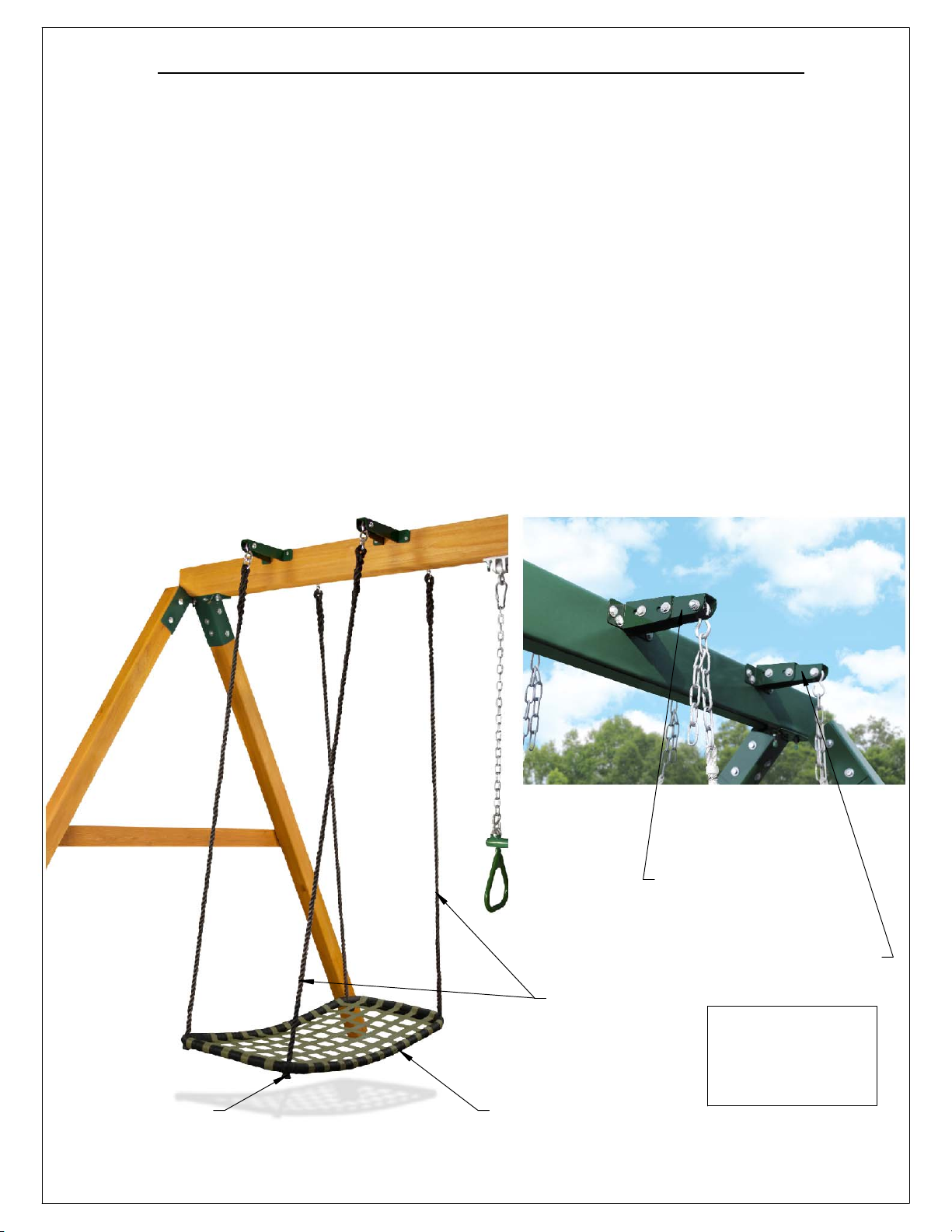
Chill 'N Swing with Glider Brackets (04-0031)
1. The Chill 'N Swing comes with a two ropes on each side fastened to steel rings. The steel
ring is approximately 2" in diameter on the outside and is approximately 1/4" thick. The
distance from the bottom of the swing to the top of the ring is approximately 71". This
distance may be adjusted by tying knots in the ropes underneath the swing seat.
The Chill 'N Swing seat is approximately 43-1/2" L x 21-1/2" W. The seat has a metal perimeter
frame with foam padding on the outside perimeter. The frame is wrapped in nylon strapping.
The seat surface is made of nylon web strap material which is wrapped around the frame
and then stitched to itself. Individual web straps are woven and sewn together.
2.See page 3 for instructions to install the Glider Brackets and hang the Chill 'N Swing.
3. A distance of 8" should exist between the outside surface of the Chill 'N Swing seat and any
adjacent swing or swing structure. Also, a minimum of 8" should exist between the bottom of
the Chill 'N Swing Seat and the protective surfacing on the ground.
4. Safety comes first when swinging. Always obey the safety rules when swinging and when
walking around a swing set. We have included a Safety Tips Guide on page 2.
5. Chill 'N Swing Weight Limit: 220 lbs. Also, do not exceed the weight limit of the swing
hangers, glider brackets or swing beam.
Tie knots
in ropes under
seat to adjust
height of swing.
REV: 1/5/2017
Dual ropes
on each side
Seat
43-1/2"L x 21-1/2"W
*FOR RESIDENTIAL USE ONLY*
*FOR CHILDREN AGES 3-11*
Example of Glider Brackets.
Chains shown belong to a
different swing. Chill n Swing
does NOT have chains.
See page 3 for installation
details.
Note: Glider Bracket
design may vary from
the pictures shown on
this page.
Page 2

SAFETY TIPS FOR SWINGS
2
On-site adult supervision is required.
Teach children not to walk close to, in front of, behind, or between moving swings or other moving playground
equipment.
Teach children to sit in and never stand on swings. (Exception to this rule is a product called "Stand -N- Swing")
Teach children not to twist the chains and ropes and not to loop them over the swing beam, since this may reduce
the strength of the chain or rope.
Teach children not to jump from swings that are in motion.
Teach children not to push empty seats. The seat may hit them and cause injury.
Teach children to sit in the center of swings with their full weight on the seats.
Teach children not to use the equipment in a manner other than intended.
Parents should have the children dress appropriately with well-fitting shoes. Loose clothing such as scarves and
ponchos should not be worn. Always take off, tie up or tuck in cords and drawstrings on children's clothing. These
things can get caught on playground equipment and strangle a child.
Teach children not to climb when the equipment is wet.
Teach children not to attach items to the playground equipment that are not specifically designed for use with the
equipment, such as, but not limited to, jump ropes, clothesline, pet leashes, cables and chains, as they may cause a
strangulation hazard.
Teach children to never wrap their legs around swing chain.
Teach children to never slide down the swing chain.
Protective surfacing under swings is recommended. "To and Fro" swings should have a fall zone extending a
minimum of 6' from the outer edge of the support structure on each side. The "fall zone" in front and back of the
swing should extend out a minimum distance of twice the height of the swing as measured from the ground to the
top of the swing support structure. Swings should have a minimum of 8 inches between them. (ASTM F-1148-12) The
bottom of a swing should not be less than 8 inches above the protective surfacing material. (ASTM F-1148-12) Home
Playground Safety Specification ASTM F-1148-12 may be purchased online. A guide for Public Playground Safety from
the U.S. Consumer Product Safety Commission may be downloaded at:
http://www.cpsc.gov//PageFiles/122149/325.pdf
A fall zone for a "tire swing" capable of unlimited lateral motion will be equal to a minimum horizontal distance of
Y + 72 in. in all directions from the pivot point of the swing. Y equals the vertical distance between the pivot point
and the top of the tire swing. Protective surfacing is recommended in the fall zone for tire swings.
If any of the following conditions are noted they should be removed, corrected or repaired immediately to prevent
injuries:
Hardware that is loose, worn, or those that have protrusions or projections.
Scattered debris, litter, rocks or tree roots.
Missing or damaged equipment components, such as swing seats.
Remove plastic swing seats and take indoors (or do not use) when the temperature drops below 32o F.
Oil all metallic moving parts monthly during the usage period.
Check swing seats, ropes, cables and chains monthly during usage season for evidence of deterioration.
Replacement should be made of any swing seat that has developed cracks in the plastic seats or has exposed metal in
the edges of the swing seat. If there are already exposed metal inserts on the edge of the seat, immediately remove
the seat and chains to prevent serious injury. Ropes, cables and chains should be removed and replaced if excessive
wear is found.
Page 3
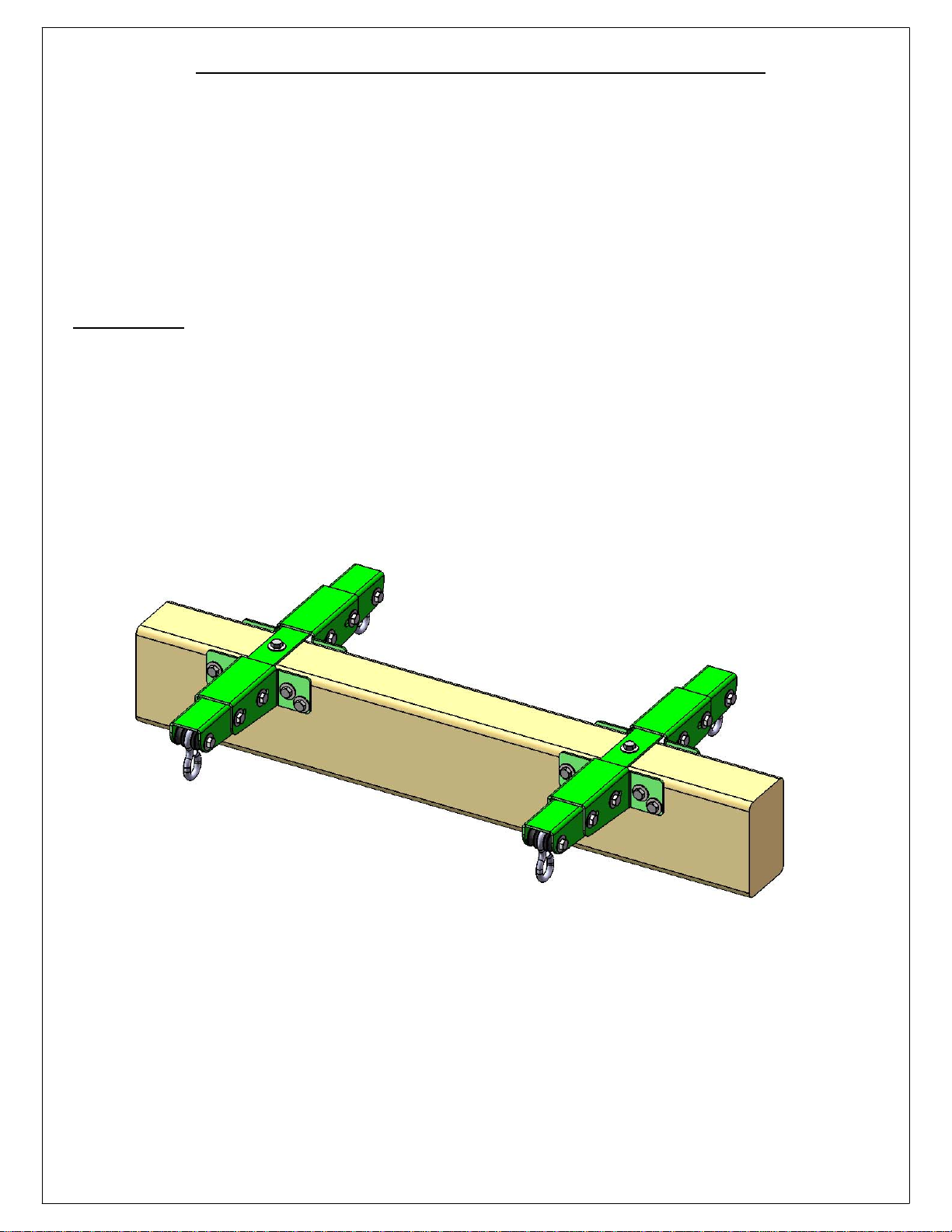
Adjustable Glider Brackets (11-4026-P)
3
1: The Adjustable Glider Bracket set comes with the brackets and all of the hardware to fasten
them to a swing beam. The swing beam may be from 2-7/8" to 4-1/2" wide.
2: The brackets come with "hook style" hangers on each side. If your glider swing has chains or
rings then those should fit onto the hooks.
3: A distance of 8" should exist betwen the brackets and the support structure or an adjacent
swing. This is described in more detail on the pages that follow.
4: Safety comes first when swinging. Always obey the safety rules when swinging and when
walking around a swing set. We have included a Safety Tips Guide on page 2.
5: INSPECTION: At the beginning and at the end of every season check the tightness of all of
the fasteners on the brackets. Inspect the brackets for signs of wear or rust. Sand and then
touch up paint any rusty areas using a nonlead-based paint meeting the requirements of
16CFR 1303. If signs of excessive wear, cracking or other deterioration is present upon
inspection discontinue use and contact your dealer for replacement parts.
6: Adjustable Glider Bracket Weight Limit: 220lbs. per pair. Also, do not exceed the weight
limit of the swing beam.
*FOR RESIDENTIAL USE ONLY*
*FOR CHILDREN AGES 3-11*
REV: 1/5/2017
Page 4
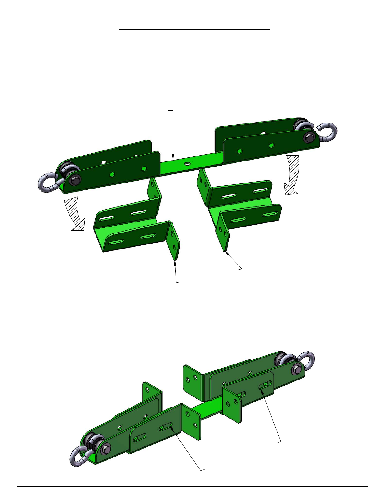
STEP 1: BRACKET LAYOUT
4
1: FIND TWO BRACKET ADJUSTERS AND ONE BRACKET BASE.
2: LAY THE TWO BRACKET ADJUSTERS ON A FLAT SURFACE FACING EACH OTHER AND PROCEED
TO PLACE THE BRACKET BASE INSIDE THE ADJUSTERS AS SHOWN IN THE DIAGRAM BELOW.
BRACKET BASE
R
E
T
S
U
J
D
A
T
E
CK
A
BR
3: LINE UP THE SLOTS IN THE BRACKET ADJUSTERS WITH THE HOLES IN THE BRACKET BASE. SPACE
THE BRACKET ADJUSTERS EVENLY APART.
S
E
L
HO
H
T
I
W
S
T
O
L
S
P
U
E
N
I
L
Page 5
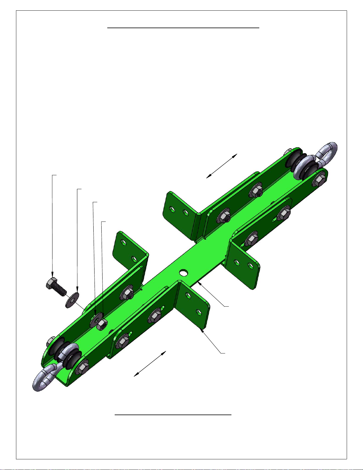
STEP 2: BRACKET ASSEMBLY
5
1: ASSEMBLE THE ADJUSTABLE GLIDER BRACKET WITH 5/16" X 3/4" HEX BOLTS AND 5/16" WASHER
FROM THE OUTSIDE AND 5/16" LOCK NUTS AND 5/16" WASHERS FROM THE INSIDE.
2: MAKE SURE TO LEAVE THE BOLTS SLIGHTLY LOOSE. THE BOLTS SHOULD BE LOOSE ENOUGH TO
MOVE THE BRACKET ADJUSTERS BACK AND FORTH ALONG THE BRACKET BASE. YOU WILL
TIGHTEN THE BOLTS IN A LATER STEP.
NOTE: A 13mm SOCKET AND WRENCH ARE REQUIRED TO TIGHTEN ALL BOLTS IN LATER STEPS.
3: PROCEED TO ASSEMBLE THE SECOND ADJUSTABLE BRACKET FOLLOWING SUB-STEPS 1 AND 2.
H
T
R
O
F
D
N
A
K
C
A
B
E
5/16" X 3/4" HEX BOLT
5/16" WASHER
D
I
L
S
5/16" WASHER
5/16" LOCK NUT
D
I
L
S
BRACKET BASE
H
T
R
O
F
D
N
A
K
C
A
B
E
BRACKET ADJUSTER
NOTE: DO NOT TIGHTEN BOLTS AND NUTS.
Page 6
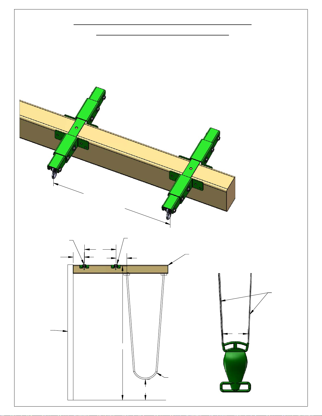
STEP 3: MOUNTING THE ADJUSTABLE
6
GLIDER BRACKET TO BEAM
1: PLACE THE ADJUSTABLE GLIDER BRACKET (1) AND ADJUSTABLE GLIDER BRACKET (2) OVER THE
TOP OF THE BEAM.
2: CALCULATE THE DISTANCE BETWEEN THE FIRST ADJUSTABLE GLIDER BRACKET AND THE
SECOND BRACKET USING THE FOLLOWING FORMULA:
A = THE CENTER TO CENTER
ADJUSTABLE GLIDER
BRACKET (2)
A = 0.04 (H) + B
ADJUSTABLE GLIDER
BRACKET (1)
DISTANCE BETWEEN
UPPERMOST SUSPENSION
POINTS OF THE
SWING ASSEMBLY.
B = THE CENTER TO CENTER
DISTANCE BETWEEN THE
SWING SEAT ATTACHMENT
POINTS.
H = THE DISTANCE BETWEEN
THE UPPERMOST
SUSPENSION POINT AND
THE PROTECTIVE
SURFACING.
ADJUSTABLE
GLIDER BRACKET
8" MINIMUM
SUPPORT POLE
(SWING LEG)
A
=
0
.
04
(
H
)
+
B
ADJUSTABLE
A
GLIDER BRACKET
8" MINIMUM
SWING BEAM
ROPES
(CHAINS)
B
H
GLIDER SWING
SWING
8" MINIMUM
(NOT MOUNTED)
Page 7
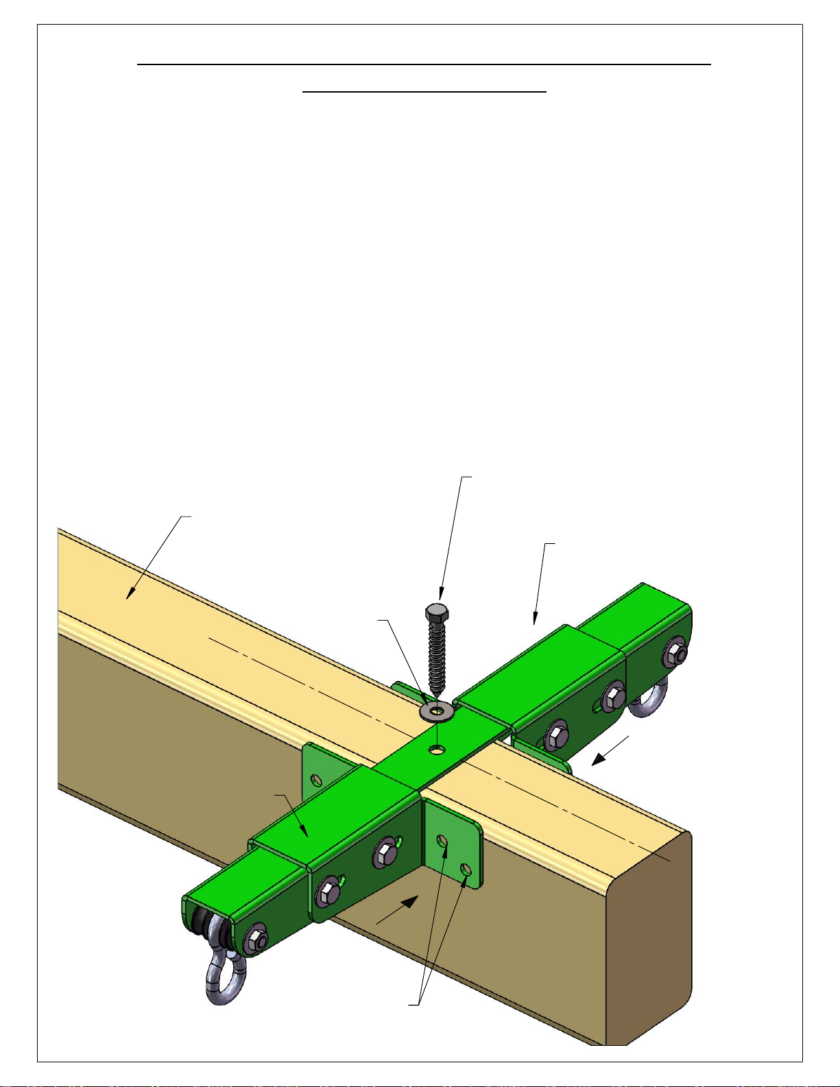
STEP 4: MOUNTING THE ADJUSTABLE GLIDER
7
BRACKET TO BEAM
1: MAKE SURE THE TOP HOLE IN THE BRACKET BASE IS CENTERED OVER THE TOP OF THE BEAM.
FASTEN THE BRACKET BASE THROUGH THE TOP HOLE TO THE BEAM USING A 5/16" X 2-1/2" LAG
SCREW AND A 5/16" WASHER.
2: SLIDE THE BRACKET ADJUSTERS AGAINST THE BEAM ON BOTH SIDES.
3: PREDRILL 11/64" HOLES 1-1/2" DEEP INTO THE BEAM THROUGH THE HOLES IN THE
FLANGES OF THE BRACKET ADJUSTERS.
4: PROCEED TO FASTEN THE SECOND ADJUSTABLE BRACKET TO THE BEAM FOLLOWING
SUB-STEPS 1 TO 3.
NOTE: A 13mm SOCKET AND WRENCH ARE REQUIRED TO TIGHTEN ALL BOLTS
AND LAG SCREWS.
BEAM
BRACKET ADJUSTER
5/16" WASHER
C
E
NT
E
R
5/16" X 2-1/2" LAG SCREW
ADJUSTABLE GLIDER
BRACKET ASSEMBLY
C
E
NT
E
R
PREDRILL 11/64"
HOLES 1-1/2" DEEP
(ALL FLANGES)
Page 8
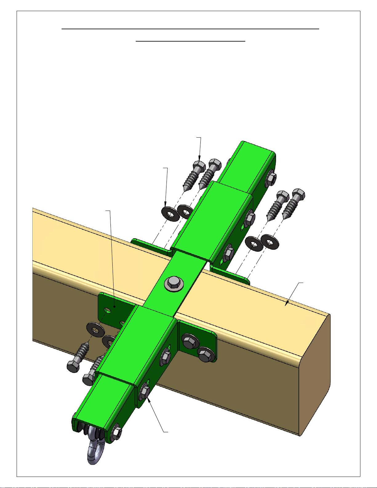
STEP 5: MOUNTING THE ADJUSTABLE GLIDER
8
BRACKET TO BEAM
1: ATTACH THE BRACKET ADJUSTER FLANGES TO THE BEAM WITH 5/16" X 1-1/2" LAG SCREWS AND
5/16" WASHERS.
2: PROCEED TO TIGHTEN ALL THE BOLTS AND NUTS FROM STEP 2 IN THE SIDES OF THE BRACKET
ADJUSTERS OF BOTH BRACKETS.
NOTE: A 13mm SOCKET AND WRENCH ARE REQUIRED TO TIGHTEN ALL BOLTS
AND LAG SCREWS.
5/16" X 1-1/2"
LAG SCREW
5/16" WASHER
BRACKET ADJUSTER
FLANGE
BEAM
TIGHTEN ALL BOLTS
AND NUTS
(SUB STEP 2)
 Loading...