

Gorilla Playsets Big Skye II, Big Skye I Assembly Manual
1
Gorilla Playsets 190 Etowah Industrial Court Canton, GA 30114 (800) 882-0272
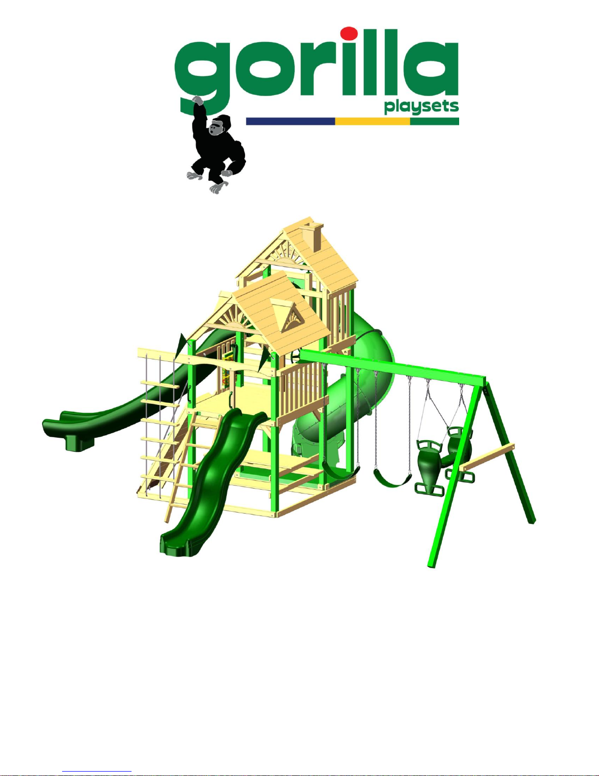
Big Skye I & II
Big Skye II Pictured Above
ASSEMBLY MANUAL
Copyright 2010Gorilla Playsets
All Rights Reserved
Latest Revision: June 28, 2010

2
IMPORTANT – PLEASE READ
As fresh lumber acclimates to its new environment, the natural
tendencies of the tree can show itself in the form of checks, or
“cracks” in the lumber. In almost all cases this is normal and it will
not affect the structural integrity of your play set.
Cosmetic defects that do not affect the structural integrity of the
product, or natural defects of wood such as warping, checking or any
other physical properties of wood that do not present a safety
hazard, are not covered by this warranty. Defects that develop
because the product is exposed to extreme climate conditions are
not covered by this warranty. Defects that develop as a result of
faulty or improper installation of the product are also not covered by
this warranty.
Most cracks are not warrantable, however if you believe that
the integrity of your play set is compromised by this natural
occurrence, please follow the warranty claim procedure found at
www.gorillaplaysets.com. Click on the “Customer Care” tab on the left
hand side of the page, then click on “Warranty Claim” and follow the
instructions.
We appreciate your purchase and know that you will enjoy your play
system for many years to come.
3
STOP…PLEASE READ!!
IF YOU HAVE MISSING OR DAMAGED PARTS OR
NEED ASSISTANCE ASSEMBLING, PLEASE
CALL Gorilla Playsets MANUFACTURING
DIRECT.
(800) 882-0272
FACTORY HOURS – MON.–FRI., 8AM-5PM EST
DO NOT RETURN THIS PRODUCT TO THE RETAILER OR CONTACT THE
RETAILER DIRECT. THE RETAILER DOES NOT STOCK COMPONENTS.
PLEASE RETAIN THESE INSTRUCTIONS FOR FUTURE REFERENCE. KEEP THEM IN A
SAFE PLACE WHERE YOU CAN REFER TO THEM AS NEEDED.
CONTACT INFO:
Gorilla Playsets
190 Etowah Industrial Court
Canton, GA 30114
Tel. (800) 882-0272
Fax. (678) 880-3329
custsrv@gorillaplaysets.com
Check for revised instructions at www.gorillaplaysets.com/category-s/92.htm

Big Skye
4
TABLE OF CONTENTS
Warranty and Safety Guidelines………………………….……………………….…..4-12
Kit Contents and Tool List…………..……………………….……………………….13-36
Framing the play set...………………………………………...……………..….steps 1 - 9
Constructing deck and lower panel boards……………………………......steps 10 - 12
Constructing and attaching ladder………....….……..………….………….steps 13 - 14
Attaching angle braces……………………………………………………….steps 15 - 16
Constructing rock - wall and securing to fort…………………………..…..steps 17 - 21
Installing upper level steps and lower level center posts………………...steps 22 - 25
Securing supports then adding picnic table and benches…………..……steps 26 - 28
Installing panel slats…………………………………………………………………step 29
Assembling Swing Beam………………………..………..….....…………...steps 30 - 36
Framing upper level…………………………………………………………..steps 37 - 46
Constructing upper deck……………………………………………………..steps 47 - 50
Installing upper level panel slats…………………..………………………………step 51
Assembling upper level roof…………………………………………………steps 52 - 61
Assembling lower level roof.…………………………………………………steps 62 - 68
Attaching upper level angle supports……………………………………….steps 69 - 70

Big Skye
5
TABLE OF CONTENTS CONTINUED
Safety handles……………………………………………………………………….step 71
Installing telescope..…..……………………………………….……………….......step 72
Installing periscope..…..……………………………………….……………….......step 73
Installing steering wheel…………………………………………………………….step 74
Mounting slide..………..……………………………………….……………….......step 75
Installing sandbox cover……………………………………………………………step 76
Installing rock wall rope…………………………………………………………….step 77
Installing rope ladder…………………………………………………………steps 78 - 79
Installing tic tac toe panel…………………………………………………………..step 80
Installing Rad Ride Slide……………………………………………………………step 81
Dormers and Chimney.……………………………………………………………..step 82
Glider swing assembly and hanging swings……………………………….steps 83 - 84
Attaching 14’ scoop slide (Model II only)…………………………………..steps 85 - 86
Installing Flag Kits............................................................................................step 87
Customer Registration Card……………………………………………………..……123
PLEASE READ OWNER’S MANUAL CAREFULLY BEFORE
STARTING ASSEMBLY!

Thank you for choosing Gorilla Playsets for your new
6
backyard playground!
We‟ve included everything you need, except tools, to build your very
own professional looking play set. When complete, your new play set
should far exceed the quality of play set kits from other build-your-own
companies. Our engineers and design team have over 30 years of
playground experience. What we‟ve developed is a play set that doesn‟t
compromise quality for simplicity. Yet you‟ll appreciate how quick and
easy construction really is! Our play set kits are designed for children
ages 3 to 11. Gorilla Playsets believes every child should have a play
set and with our kits they can! You can rest assured your new play set is
safe, durable and designed to hold up to the elements. As parents
ourselves, we know how important the security and well- being of our
children is, and this shows in all of our products.
Each play set features our step-by-step 3D illustrated manual,
patented powder coated swing beam bracket, heavy-duty swing belts
with chains, slide(s), accessories, plus all the required hardware and premilled lumber.
Quality Lumber
At Gorilla Playsets, we use only the finest, hand selected lumber
available. You can be assured that our lumber is strong, durable, and
conforms to the national standards for use in children‟s play equipment.
It‟s this quality that allows us to offer a 10 year warranty on the lumber
used in our play sets.

Limited Manufacturers Warranty
7
Gorilla Playsets® (“Gorilla”) warrants its play sets to be free from defects in workmanship and materials,
under normal use and conditions at its original installation, for 10 years for structural wood components
and for one year for all other components (e.g., hardware, plastics, tarps, rope ladder, etc.).
Cosmetic defects or natural defects of wood (e.g., warping, seasonal checking or cracking, knots, or
knot holes, etc.) that do not affect the structural integrity of the product are not covered by this warranty.
Defects that develop because the product is exposed to extreme climate conditions, or that develop as a
result of faulty or improper installation of the product, are not covered by this warranty. Fading or
discoloration of any part or accessory, cracks in plastic components, surface rust on hardware, and chips
on powder coated materials are not considered defects in material as long as they do not affect the
functionality or structural integrity of the part or component.
It is the owner‟s responsibility to properly maintain the play set. Instructions for proper maintenance
can be found on Gorilla‟s website. Imperfections or defects that develop because of a failure to properly
maintain the play set are not covered by this warranty.
Gorilla will repair or, at its discretion, replace any part within the stated warranty period that is
defective in workmanship or materials. This decision is subject to verification of the defect, which, at
Gorilla‟s discretion, may be accomplished by submitting photographs or by delivery of the defective part to
Gorilla. Any warranty claim must include proof of purchase, including the date of purchase.
This warranty is valid only if the product is used for the purpose for which it was designed and installed
at a residential, single-family dwelling. This warranty is void if the product is put to commercial or
institutional use. This warranty does not cover (a) products that have been damaged by acts of God,
negligence, misuse, or accident, or that have been modified or repaired by unauthorized persons; (b) the
cost of labor; or (c) the cost of shipping the product, any part, or any replacement product or part.
GORILLA DISCLAIMS ALL OTHER REPRESENTATIONS AND WARRANTIES OF ANY KIND, EXPRESS,
IMPLIED, STATUTORY, OR OTHERWISE, INCLUDING THE IMPLIED WARRANTIES OF MERCHANTABILITY
AND FITNESS FOR A PARTICULAR PURPOSE. GORILLA WILL NOT BE LIABLE FOR ANY INCIDENTAL OR
CONSEQUENTIAL DAMAGES
transferrable and does not extend to the owners of the product subsequent to the original purchaser, and
only applies to the product as originally installed (in other words, installing the product and then later
disassembling and reinstalling the product at the same or another location voids the warranty). Some
states do not allow limitations on implied warranties or exclusion of incidental or consequential damages,
so these restrictions may not be applicable to you. This warranty gives you specific legal rights. You may
also have other rights which vary from state to state.
IMPORTANT SAFETY GUIDELINES
This product is intended for residential use only and not intended for use in any public setting. A safety
surface such as mulch or recycled tire should be used under the play set to prevent injury from falls. Also
a 6 foot safety zone should be used around the entire play set.
As with any home project, good judgment and respect for power tools will greatly reduce the risk of
injury. Gorilla recommends you follow all tool manufacturers‟ safety guidelines. Always wear eye
protection and safety gloves to prevent injury. In several phases of construction two people may be
required for lifting and securing of lumber. While play set is being constructed, please keep children off
the equipment until the project is complete. Bolts and screw heads should be checked regularly for
tightness. The ground ladder, rope ladder, slide, swings and other areas where children spend a majority
of their playtime should be checked more frequently.
Gorilla shall not be liable for incidental, indirect or consequential damages or injuries that result from
the building and/or playing on our play sets. Adult supervision is recommended anytime a play set is being
used.
. This warranty is valid only in the United States of America, is non-

WEIGHT LIMITS FOR GORILLA PLAYSETS
8
FORT PLATFORMS: 800 LBS. TOTAL WEIGHT
SWING BELTS: 175 LBS.
GLIDER SWINGS: 70 LBS. PER CHILD
TRAPEZE: 125 LBS.
FULL BUCKET SWING: 50 LBS.
TODDLER BUCKET SWING: 50 LBS.
INFANT SWING: 35 LBS.
TIRE SWING: 125 LBS. TOTAL WEIGHT
ROPE LADDER: 75 LBS.
ROCK WALL: 150 LBS.
ALL SLIDES: 125 LBS.
Gorilla recommends that the weight limits for all components must not be exceeded.
Failure to adhere to these and other safety guidelines could result in damage to the play
set and injury to the users.

Safety and Maintenance Tips for Your New Play Set:
9
NOTE: Your children’s safety is our #1 concern. Observing the following statements and warnings
reduces the likelihood of serious or fatal injury. Please review these safety rules regularly with
your children.
This play set is designed for the use of 4 occupants who have a combined weight not
exceeding 800 pounds on the elevated floor, 3 occupants who have a combined weight of
525 pounds on the swing area, for a total Unit capacity of 7 occupants who have a combined
weight of 1325. (this weight is not including the picnic table area)
On-site adult supervision is required.
Teach children not to walk close to, in front of, behind, or between moving swings or other
moving playground equipment.
Teach children to sit in and never stand on swings
Teach children not to twist the chains and ropes and not to loop them over the swing beam,
since this may reduce the strength of the chain or rope.
Teach children not to jump from swings or other playground equipment in motion.
Teach children to not push empty seats. The seat may hit them and cause serious injury.
Teach children to sit in the center of the swings with their full weight on the seats.
Teach children not to use the equipment in a manner other than intended.
Teach children to always go down slides feet first. Never slide headfirst.
Teach children to look before they slide to make sure no one is at the bottom.
Teach children to never run up a slide, as this increases their chances of falling.
The parents should have the children dress appropriately with well-fitting shoes. Loose
clothing such as scarves and ponchos should not be worn. Always take off, tie up or tuck in
cords and drawstrings on children‟s clothing. These things can get caught on playground
equipment and strangle a child.
Teach children not to climb when the equipment is wet.
Teach children to never jump from a fort deck. They should always use the ladder, ramp or
slide.
Teach children to never crawl or walk across the top of monkey bars.
Teach children to never crawl on top of a fort roof.
Verify that any suspended climbing ropes, chains, or cables are secured at both ends and
that they cannot be looped around an adult hand.
Teach children not to attach items to the playground equipment that are not specifically
designed for use with the equipment, such as, but not limited to, jump ropes, clothesline, pet
leashes, cables and chain as they may cause a strangulation hazard.
Teach children to never wrap their legs around swing chain.
Teach children to never slide down the swing chain.
WARNING: Children must NOT use this play set until unit has been completely
assembled and inspected by an adult to insure set has been properly installed
and anchored.

Safety and Maintenance Tips for Your New Play Set: (continued)
10
Playgrounds should be inspected on a regular basis. If any of the following conditions are
noted, they should be removed, corrected, or repaired immediately to prevent injuries.
Hardware that is loose, worn or that has protrusions or projections
Exposed equipment footings
Scattered debris, litter, rocks, or tree roots
Splinters, large cracks, and decayed wood components.
Deterioration and corrosion on structural components, which connect to the ground
Missing or damaged equipment components, such as handholds, guardrails, swing
seats.
Check all nuts and bolts frequently during the usage season and tighten as required.
(But not so tight that you crack the wood) We recommend you check the swing beam
and hardware often due to wood expansion and contraction. It is particularly important
that this procedure be followed at the beginning of each season.
Remove plastic swing seats and take indoors or do not use when the temperature drops
below 32°F.
Oil all metallic moving parts monthly during the usage period.
Check all coverings for bolts and sharp edges twice monthly during usage season to be
certain they are in place. Replace when necessary. It is especially important to do this at
the beginning of each new season.
Check swing seats, ropes, cables and chains monthly during usage season for evidence
of deterioration. Replacement should be made of any swing seat that has developed
cracks in the plastic seats or has exposed metal in the edges of the swing seat. If there
are already exposed metal inserts on the edge of the seat, immediately remove the
seats and chains to prevent serious injury. Ropes, cables and chains should be removed
and replaced if excessive wear is found. Contact Gorilla for warranted replacement
parts.
For rusted areas on metallic members such as monkey bars, hand supports brackets,
etc.; sand and repaint, using a non lead-based paint meeting the requirements of Title
16 CRF Part 1303.
Inspect wood parts monthly. The grain of the wood sometimes will lift in the dry season
causing splinters to appear. Light sanding may be necessary to maintain a safe playing
environment. If you are treating your play set with stain regularly, it will help prevent
severe checking/splitting and other weather damage.
Once or twice a year, depending on your climate conditions, you must apply some type
of protection (sealant) to the wood of your unit. Prior to the application of sealant,
lightly sand any “rough” spots on your set. Please note this is a requirement of your
warranty.
Creating and maintaining the play set on a level location is very important. As your
children play, your play set will slowly dig its way into the soil, and it is very important
that it settles evenly. Make sure the play set is level and true once each year or at the
beginning of each play season.
Rake the surface periodically to prevent compaction and maintain appropriate depths.
Disposal Instructions:
disassembled and disposed of in such away that no unreasonable hazards will exist at the time
When the play set use is no longer desired, it should be
the unit is discarded.
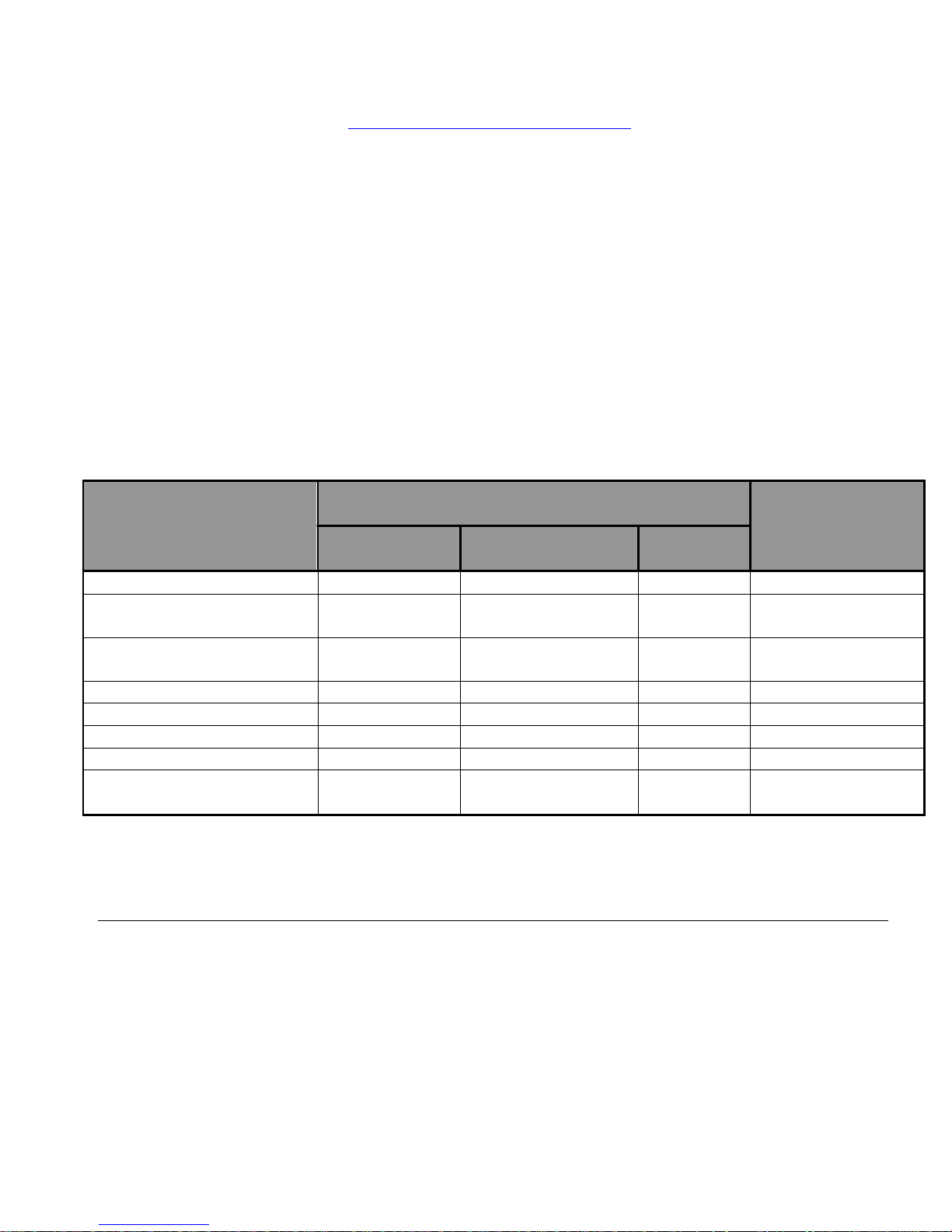
Play Set Surfacing Recommendations:
Material
Uncompressed
Depth
Compressed
Depth
6" (152mm)
9" (228mm)
12"
(304mm)
to 9" (228mm)
Wood Chips
7' (2.13m)
10' (3.05m)
11' (3.35m)
10' (3.05m)
Double-Shredded bark
mulch
6' (1.83m)
10' (3.05m)
11' (3.35m)
7' (2.13m)
Engineered Wood Fibers
6' (1.83m)
7' (2.13m)
>12'
(3.66m)
6' (1.83m)
Fine Sand
5' (1.52m)
5' (1.52m)
9' (2.74m)
5' (1.52m)
Coarse Sand
5' (1.52m)
5' (1.52m)
6' (1.83m)
4' (1.22m)
Fine Gravel
5' (1.52m)
7' (2.13m)
10' (3.05m)
6' (1.83m)
Medium Gravel
5' (1.52m)
5' (1.52m)
6' (1.83m)
5' (1.52m)
Shredded Tires*
10-12' (3.0-
3.6m)
N/A
N/A
N/A
*This data is from tests conducted by independent testing laboratories on a 6-inch depth of uncompressed shredded tire samples produced by four manufacturers. The
tests reported critical heights, which varied from 10 feet to greater than 12 feet. It is recommended that persons seeking to install shredded tires as a protective surface
request test data from the supplier showing the critical height of the material when it was tested in accordance with ASTM F1292.
11
Below are some of the recommendations that the U.S. Consumer Product Safety Commission (CPSC)
offers from its
1. Protective Surfacing - Since almost 60% of all injuries are caused by falls to the ground, protective
surfacing under and around all playground equipment is the most critical safety factor on playgrounds.
Certain manufactured synthetic surfaces also are acceptable; however, test data on shock absorbing
performance should be requested from the manufacturer.
Asphalt and concrete are unacceptable. They do not have any shock absorbing properties. Similarly, grass
and turf should not be used. Their ability to absorb shock during a fall can be reduced considerably
through wear and environmental conditions.
Certain loose-fill surfacing materials are acceptable. Surfacing materials are acceptable, such as the types
and depths shown in the table.
Handbook for Public Playground Safety
www.cpsc.gov/cpscpub/pubs/325.pdf
. The guide can be downloaded in full at
Fall Heights and Materials
It should be recognized that all injuries due to falls cannot be prevented no matter what surfacing material is used.
2. Fall Zones - A fall zone, covered with a protective surfacing material, is essential under and around
equipment where a child might fall. This area should be free of other equipment and obstacles onto which
a child might fall. Stationary climbing equipment and slides should have a fall zone extending a Minimum
of 6' in all directions from the perimeter of the equipment.
Swings should have a fall zone extending a minimum of 6' from the outer edge of the support structure on
each side. The fall zone in front and back of the swing should extend out a minimum distance of twice the
height of the swing as measured from the ground to the top of the swing support structure.
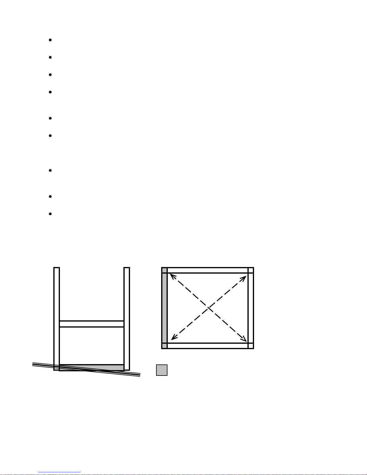
LEVELING YOUR FORT DURING ASSEMBLY
= AREA TO BE SCORED AND
CHANNELED FOR LEVELNESS
THE DIAGONAL
MEASUREMENTS
SHOULD BE THE
SAME FROM
CORNER POST TO
CORNER POST. IF
NOT, ADJUST
FORT SO THAT
THE DISTANCE IS
EQUAL.
12
Complete the steps which will be the basic frame of the fort {i.e. four corner posts with
base (sand box boards) and deck supports}
Position in the most level area chosen for the play set, keeping in mind the location and
size of the swing beam, ladder, slides, etc. that extend off the fort.
Once the frame is in the final position, check for vertical and horizontal levelness to
determine which side(s) will need to be dug into the ground to level the play set.
With a shovel, score the ground around the outside edges of the sandbox boards on the
„high‟ side of the fort. This is the area that will be dug in. Make sure to score deep
enough; the scored lines will be your digging template.
Push the frame off and away from the scored area, far enough to dig and remove dirt to
reach the appropriate depth.
Dig a channel along the scored line(s) for the base of the fort (corner post and sandbox
boards) to rest into. Dig the channel(s) to the same level depth. The bottom of the
channel(s) should be level to each other so your frame doesn‟t teeter or rock because the
channel(s) are uneven.
Once you have removed enough grass and dirt, slide/push the frame into the channel(s).
Place a level on the vertical and horizontal boards of the frame to determine if enough soil,
or too much, was removed.
Repeat this process until the basic frame is plumb and level and in its final position before
completing the rest of the assembly.
Measure to make sure fort is square.
Important: if you require a channel depth of more than 6”, then we recommend you have your
play set area professionally graded before completing assembly.
Example play area:

Big Skye
13
KIT CONTENTS
COMPONENTS
Description Qty Check List
(Swings, Slides, Accessories)
Swingbelts w/ Chains 2 __________
Trapeze Bar w/ Rings 1 __________
Glider Swing 1 __________
Steering Wheel 1 __________
Telescope 1 __________
Periscope 1 __________
Rope Ladder 1 __________
10’ Wave Slide 1 __________
Rad Ride Tube Slide 1 __________
14’ Scoop Slide (Model II Only) 1 __________
Dormer 2 __________
Chimney 1 __________
Rock Wall Rocks 10 __________
Safety Handles (Pair) 2 __________
Flags 2 __________
Tic Tac Toe Panel 1 __________
Sandbox Cover 1 __________
The Big Skye Assembly Manual 1 __________
Description
(Fort Hardware) see following pages
Description
(Swing Beam Hardware) see following pages
Description
(Wood Components) see following pages
REQUIRED TOOL LIST
Standard or Cordless Drill w/ Phillips Bit (#2 square bit provided)
Extension Cord (if using standard drill)
Locking Pliers (Vise Grips, For Carriage Bolts)
1/8” Drill Bit
3/8” Drill Bit
7/8” Paddle Bit
½” Wrench and Socket
½” Deep Well Socket
9/16” Deep Well Socket
9/16” Wrench and Socket
Level
Tape Measure
Hammer
Pencil
Shovel
Rubber Mallet
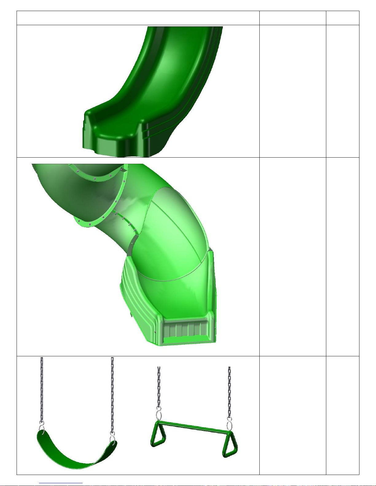
WAVE SLIDE
LADDER
SWING BELTS (2)
GLIDER SWING (1)
21’
19’
ROCK WALL
ROPE LADDER
RAD RIDE
SLIDE
14
Please familiarize yourself with the manual, parts/components and general construction
process of your new playset before getting started.
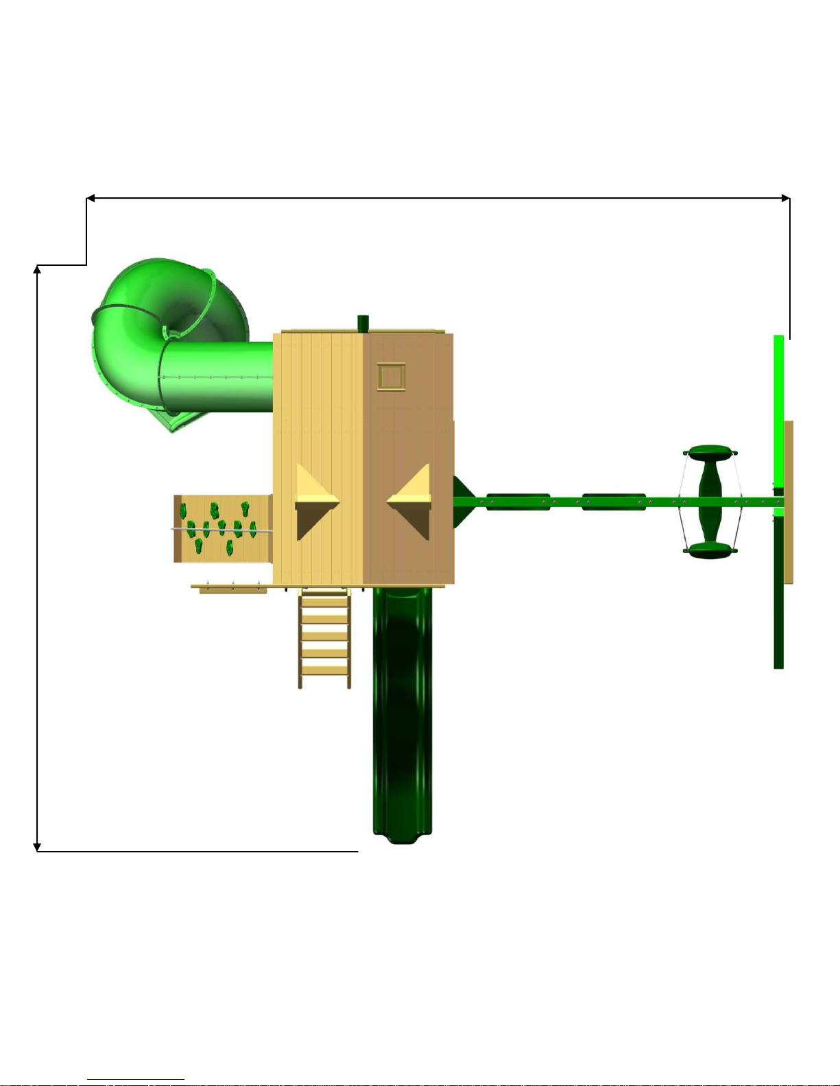
SITE PLAN: BIG SKYE I
Playset height: 13’ 6”
Approximate assembly time:
8-12 Hours
{ 6 foot unobstructed safety perimeter around playset recommended }
Please familiarize yourself with the manual, parts/components and general construction
WAVE SLIDE
LADDER
SWING BELTS (2)
GLIDER SWING (1)
26’
21’
ROCK WALL
ROPE LADDER
RAD RIDE
SLIDE
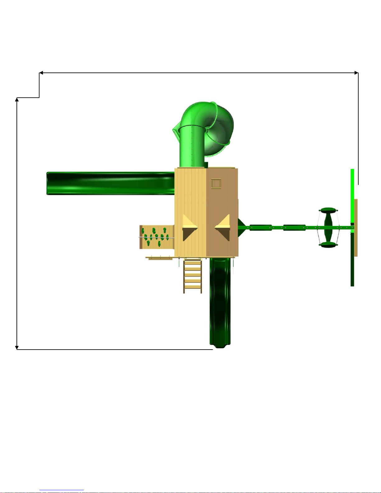
SCOOP SLIDE
15
process of your new playset before getting started.
SITE PLAN: BIG SKYE II
Playset height: 13’ 6”
Approximate assembly time:
8-12 Hours
{ 6 foot unobstructed safety perimeter around playset recommended }
Helpful Installation Hints

Depending on your experience, assembly of Gorilla Playsets can take as little as 6 hours up to
General Info To Review Before Installation
16
24 hours, depending on size, after inventory of parts; therefore, we recommend you set
aside a full two days for assembly.
Identify all of the parts for your play set. Empty each box and lay out boards so you can see
each part. Your instruction book will have detailed drawings that will make it easy for you to
recognize individual parts. Keep all hardware and metal parts separate from wooden pieces.
After everything is laid out, check carefully to ensure all parts are present. Make sure there
are no broken boards.
Find an area to sort your hardware. It is best to open the hardware on a solid surface so that
you do not lose any pieces in the grass. This will save time and familiarize you with all the
different pieces in the hardware bag.
Important note: Wood has some natural defects such as knots, surface cracks, etc… We
reject parts that are structurally defective. We use a high quality lumber in our structures;
however, you should inspect each part for splinters or rough spots and sand them smooth to
prevent injury.
After familiarizing yourself with all of the components, read all instructions thoroughly.
Reading instructions after you have studied the parts will help you understand more clearly
the installation process, and help to eliminate unnecessary mistakes.
Pay close attention to the diameter and length of each bolt and screw.
Never tighten hardware completely at first. It helps to have some adjustment for bolt
alignment while you are attaching parts together. After everything is square, tighten each
joint.
After the main unit is assembled it is critical that the floor is level and square. If the main
frame is not level, the walls and floor will be out of square.
After you complete installation, make sure every bolt, screw, and nut is tight, and every
board is secure. Wood will expand and contract with the seasons.
Check all bolt connections and swing hangers every two weeks.
Place the set on level ground, not less than 6ft from any structure or obstruction such as a
fence, garage, house, overhanging branches, laundry lines, or electrical wires.
READ! VERY IMPORTANT!
If you are missing parts or have questions regarding the installation of our quality product PLEASE
call us directly at the factory (1-800-882-0272). Our trained staff will be happy to assist you.
Customer service hours:
Monday thru Friday 8AM – 5PM EST
E-mail: custsrv@gorillaplaysets.com
This page is a list of definitions and explanations used throughout our instructions to aid you
Counter-sunk holes- Many of the parts that will be used have counter-sunk holes. A
counter-sunk hole is one that surrounds one side of a thru hole, but does not extend through the
wood itself. When using a counter-sunk hole the bolt will be inserted through the thru hole and
either the head of the bolt and washer or nut and washer will occupy the counter sunk hole.
Lag Screws- Lag screws are used in the construction of our play sets to enhance the
structural integrity of the unit. There will not be predrilled holes in the post for lag screw
installation. Lag screws are self-tapping, though if you are using a manual socket wrench it may
be necessary to tap the head of the lag screw with a hammer. You should also be sure to tighten
the lags completely. Power tools such as an impact wrench or power drill should have enough
torque to drive the lag screws without using a hammer, but make sure not to over tighten as this
can cause the threads to “strip out” in the post.
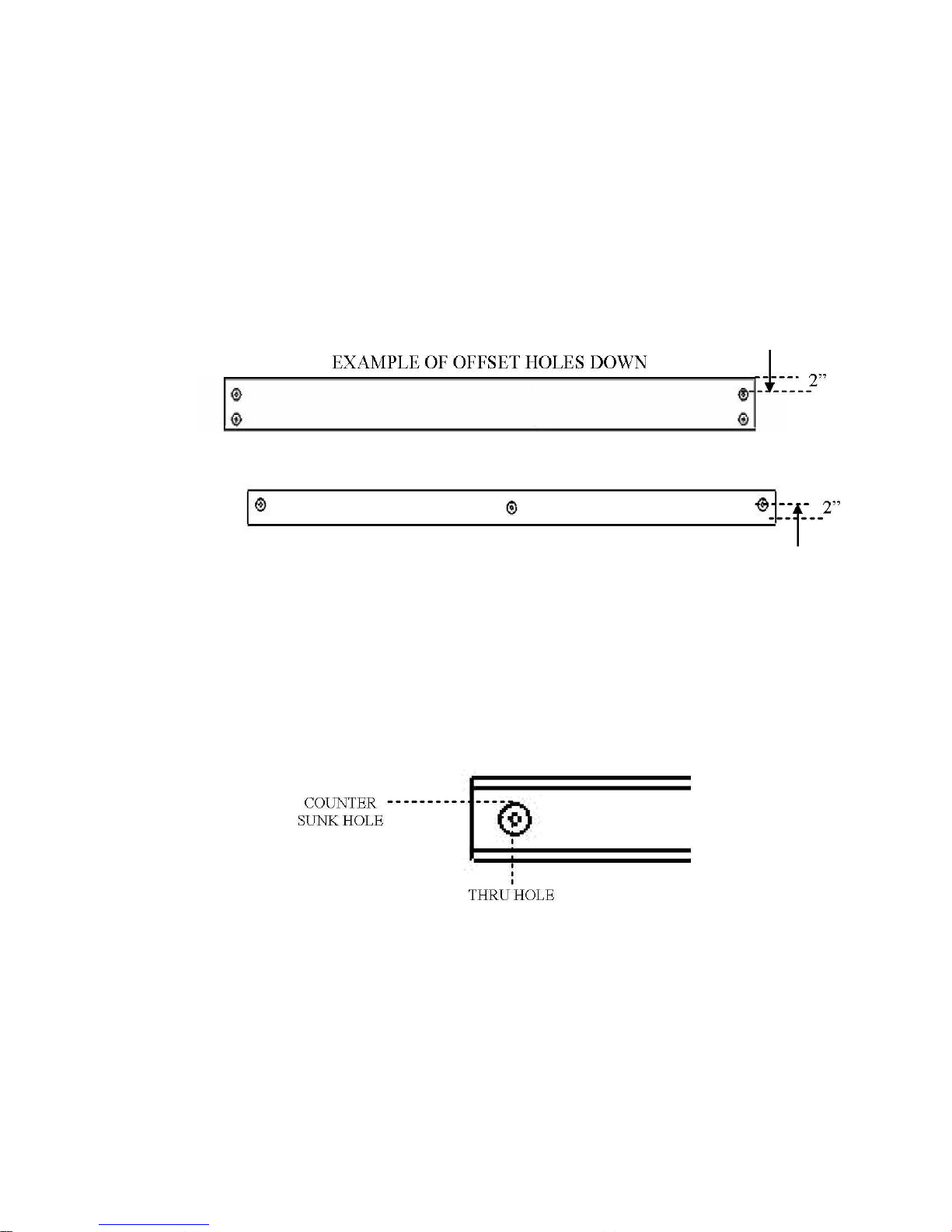
EXAMPLE OF OFFSET HOLES UP
Offset Holes- Throughout the installation procedures we will refer to parts with offset holes.
This refers to the orientation of the holes on the board. An offset hole is one that is closer to one
side than it is the other or in other words, it is not centered on the board. In the procedures you
will be instructed to attach the boards with the holes offset up or with the holes offset down. This
refers to which side of the board the hole/holes should be closer to. Offset holes up= hole/holes
will be closer to the top of the board. Offset holes down= hole/holes will be closer to the bottom
of the board. Note: some parts do not have offset holes, but instead the holes are on center.
Therefore there will not be any reference to how to offset these parts.
17
in the assembly of your play set.
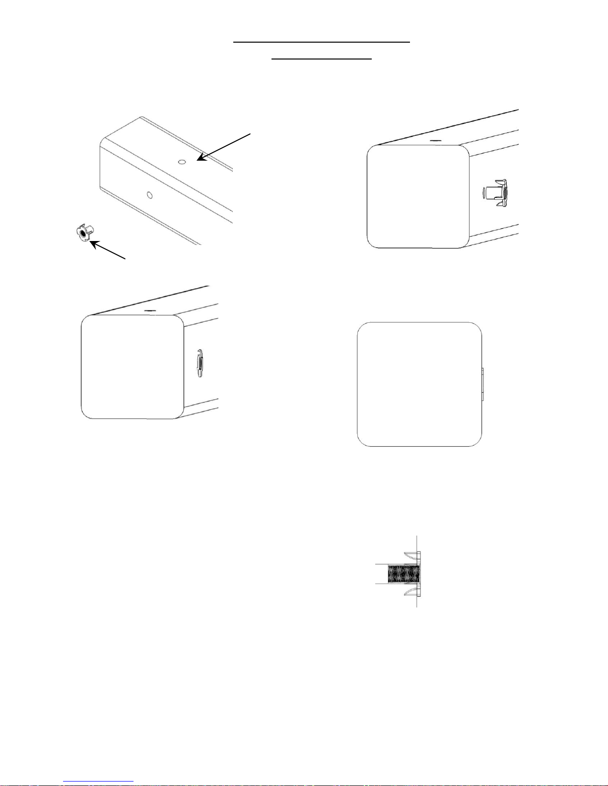
Common installation practice
Corner Post
T-nut
Insert the barrel of the T-nut into the
predrilled hole. Using a smooth faced
hammer, drive the T-nut until the face
of the T-nut is flush to the wood.
This picture shows the T-nut insert and
installed flush to the wood.
This picture shows an end view of the T-nut
insert and installed flush to the wood.
WARNING: DO NOT EMBED THE TOP OF THE
T-NUT INTO THE FACE OF THE WOOD
Cross Section end views, you are looking at an Xray view of the post and T-nut. The barrel of the
T-nut is in the corner post the line is the face of
the wood.
Flush
Correct
18
Installing T-nuts
When installing T-nuts into the wood, use a smooth faced hammer to set the face
of the T-nut flush into the wood.
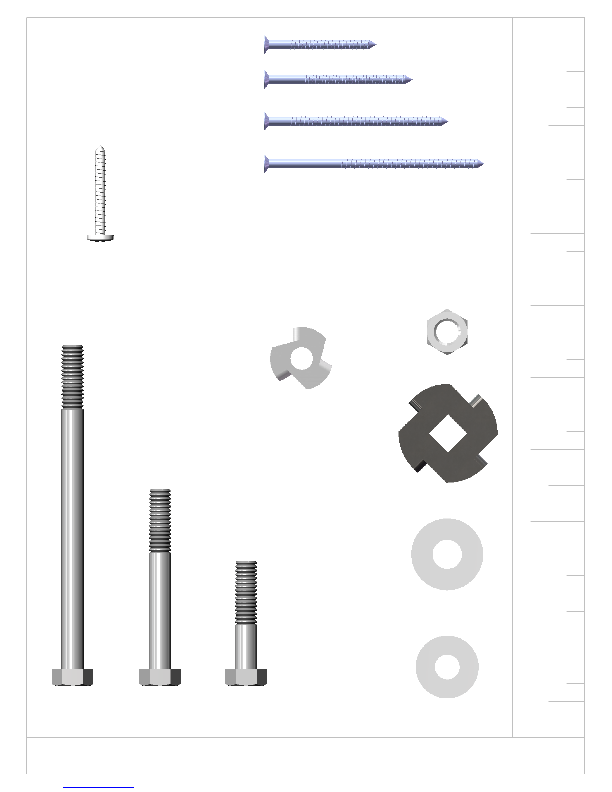
#8 X 1-1/2"
19
WOOD SCREW
QTY: 234
#8 X 2"
WOOD SCREW
QTY: 291
#8 X 2-1/2"
WOOD SCREW
QTY: 120
9
#14 X 1-1/4"
PAN HEAD SCREW
QTY: 7
#8 X 3"
WOOD SCREW
QTY: 12
5/16" TEE NUT
QTY: 62
3/8" LOCK NUT
QTY: 21
8
7
6
5
5/16 X 4-1/2"
HEX BOLT
QTY: 49
5/16 X 2-1/4"
HEX BOLT
QTY: 3
5/16 X 1-1/2"
HEX BOLT
QTY: 8
4
TORQUE WASHER
QTY: 19
3
2
3/8" WASHER
QTY: 38
1
5/16" WASHER
QTY: 96
USE THE RULER TO THE RIGHT TO MEASURE YOUR BOLTS AND SCREWS. PICTURE VIEWS SHOWN
ABOVE ARE 1:1 SCALE AND CAN BE USED TO MATCH BOLT AND SCREW SIZES.
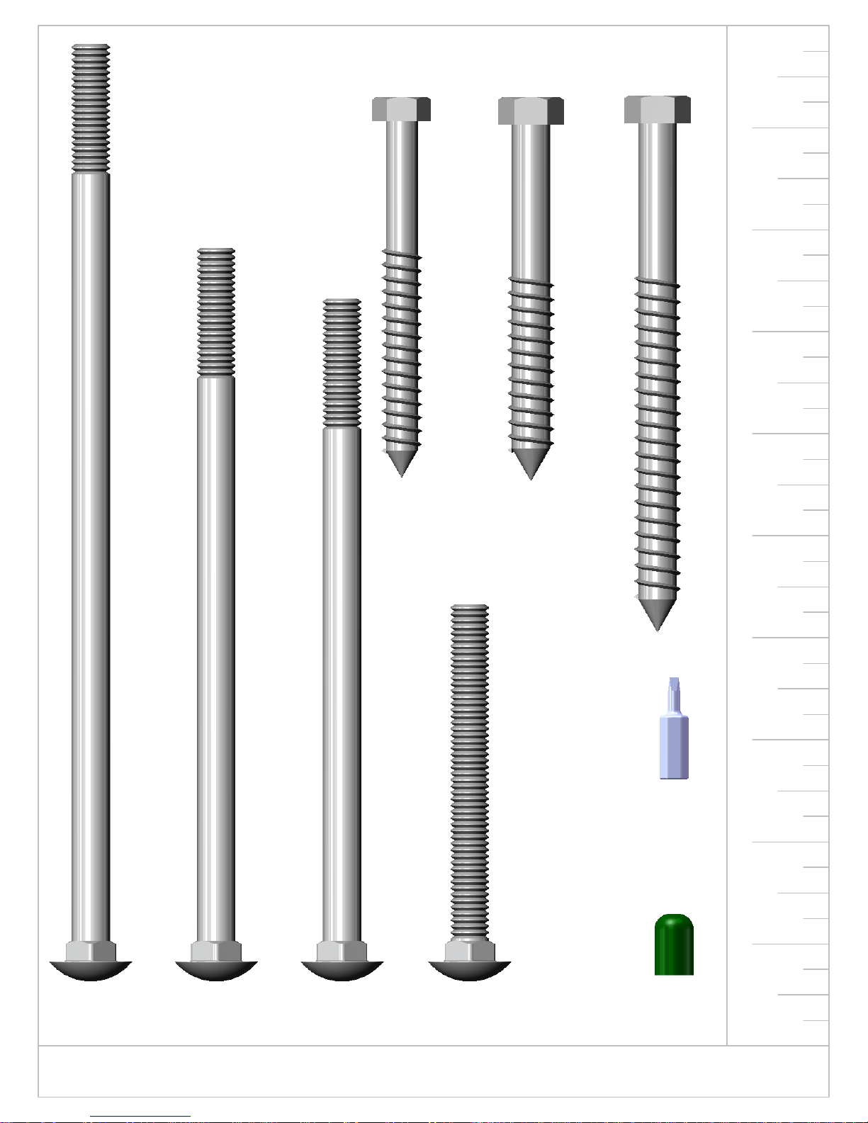
5/16 X 3-1/2"
20
HEX LAG SCREW
QTY: 36
3/8 X 3-1/2"
HEX LAG SCREW
QTY: 10
3/8 X 5"
HEX LAG SCREW
QTY: 7
9
8
7
6
#2 SQUARE
DRILL BIT
QTY: 1
5
4
3
2
1
3/8 x 9"
CARRIAGE BOLT
QTY: 1
3/8 x 7"
CARRIAGE BOLT
QTY: 14
USE THE RULER TO THE RIGHT TO MEASURE YOUR BOLTS AND SCREWS. PICTURE VIEWS SHOWN
ABOVE ARE 1:1 SCALE AND CAN BE USED TO MATCH BOLT AND SCREW SIZES.
3/8 x 6-1/2"
CARRIAGE BOLT
QTY: 4
3/8 x 3-1/2"
CARRIAGE BOLT
QTY: 2
PLASTIC
BOLT CAP
QTY: 21
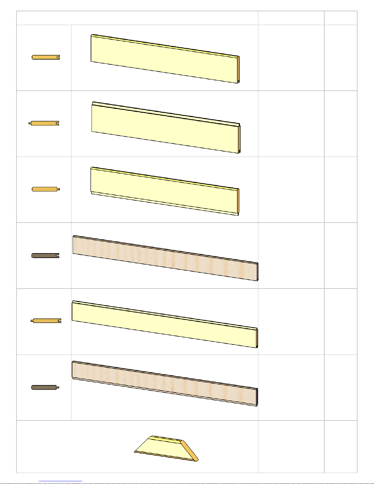
PICTURE
21
DESCRIPTION
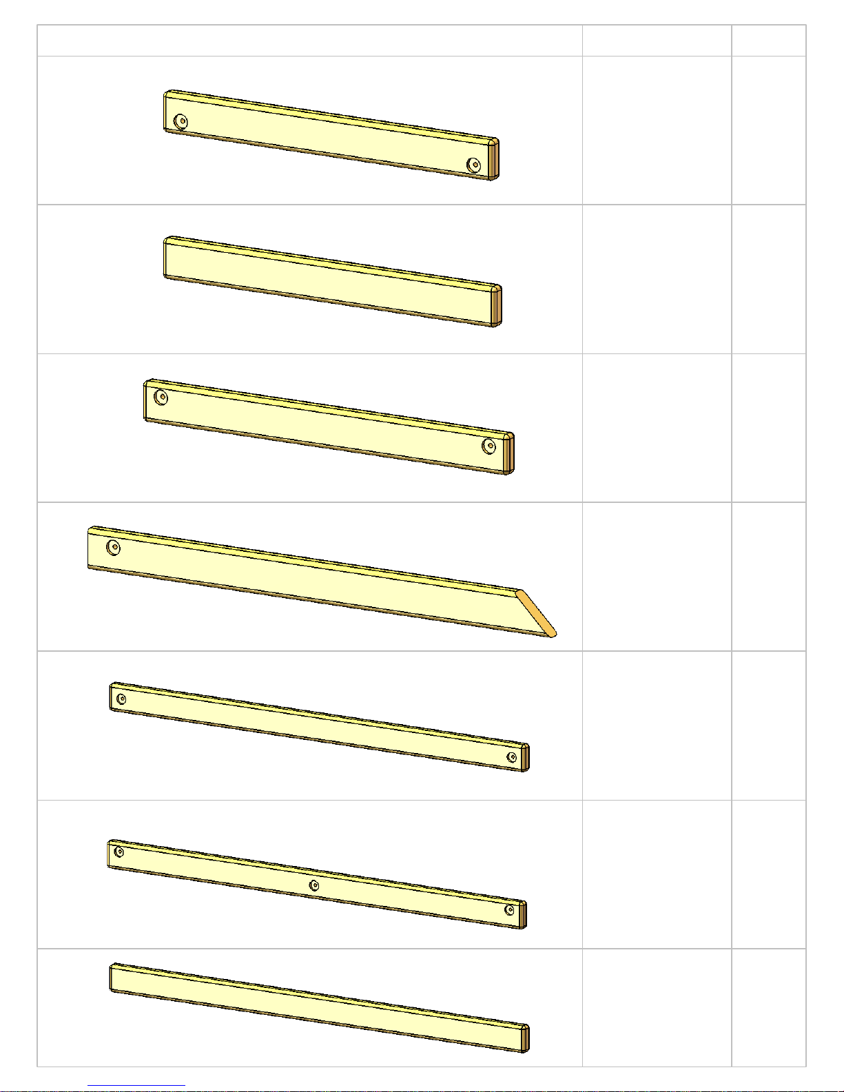
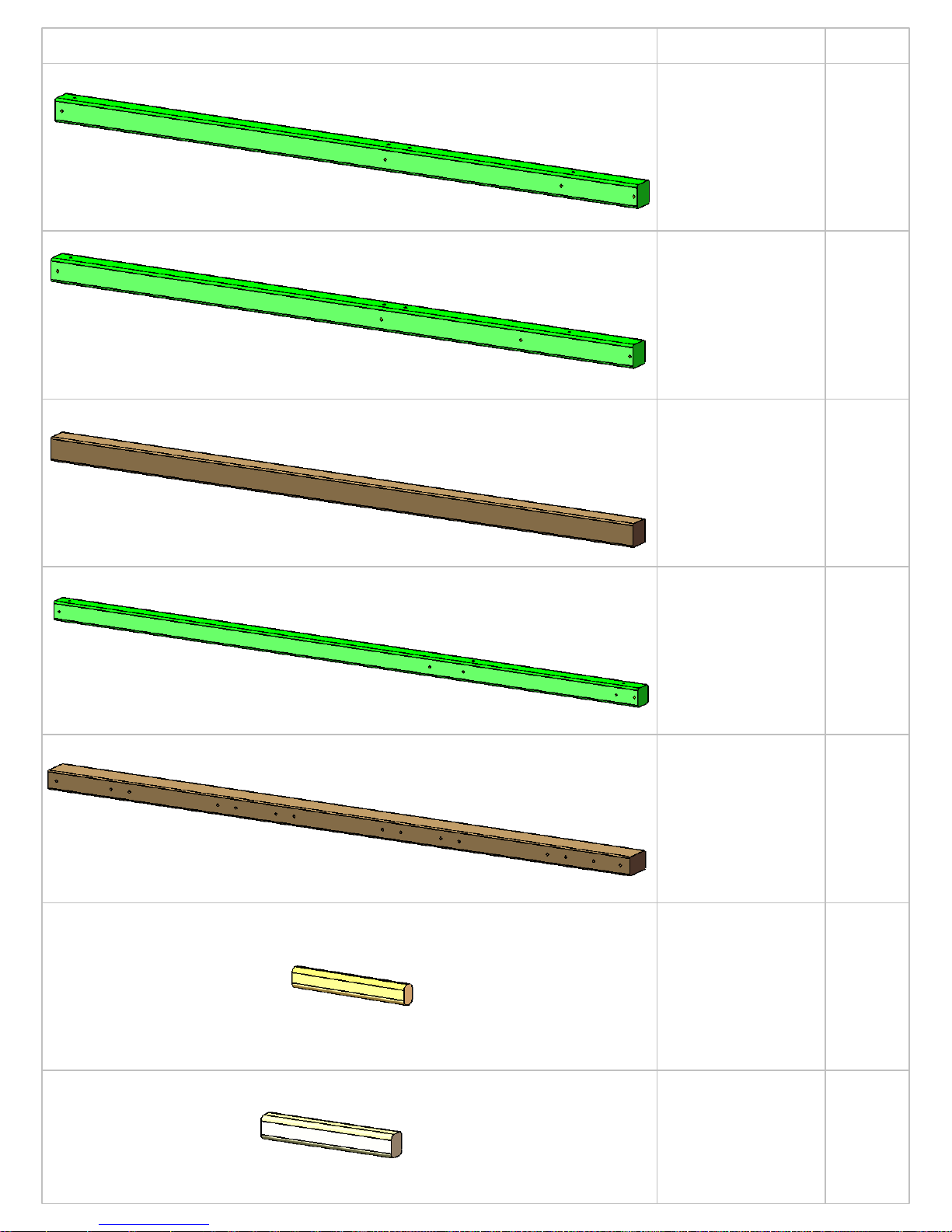
1 X 5 X 30-3/4"
GROOVE-ONLY
UPPER LEVEL
ROOF STARTER
1 X 6 X 30-3/4"
TONGUE AND
GROOVE UPPER
LEVEL ROOF
BOARD
1 X 5 X 30-3/4"
TONGUE-ONLY
UPPER LEVEL
ROOF FINISHER
QTY.
2
14
2
1 X 5 X 58"
GROOVE-ONLY
LOWER LEVEL
ROOF STARTER
1 X 6 X 58"
TONGUE AND
GROOVE
LOWER LEVEL
ROOF BOARD
1 X 5 X 58"
TONGUE-ONLY
LOWER LEVEL
ROOF FINISHER
2
14
2
2 X 4 X 13"
LOWER LEVEL
ANGLE SUPPORT
4
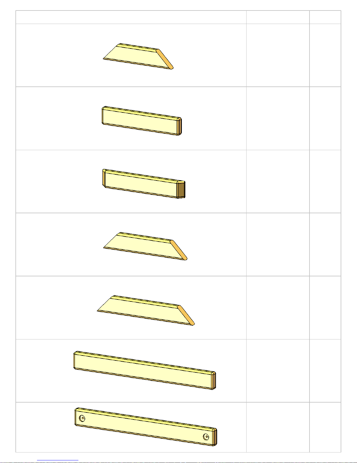
PICTURE
22
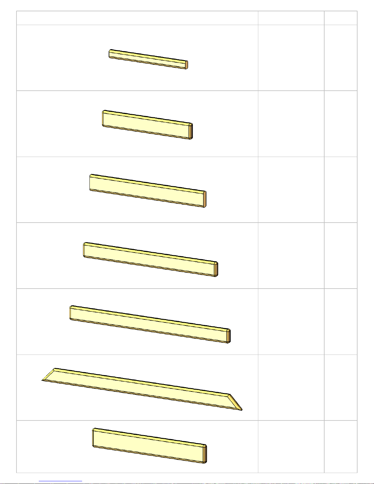
DESCRIPTION
2 X 4 X 15"
UPPER LEVEL
ANGLE SUPPORT
2 X 4 X 17"
LADDER STEP
2 X 4 X 18"
CENTER PICNIC
TABLE SUPPORT
QTY.
2
5
1
2 X 4 X 18"
LOWER LEVEL
ANGLE SUPPORT
2 X 4 X 21"
UPPER LEVEL
ANGLE SUPPORT
2 X 4 X 30-3/4"
UPPER LEVEL
DECK SUPPORT
4
2
4
2 X 4 X 30-3/4"
UPPER LEVEL END
DECK SUPPORT
(TWO HOLES ON
CENTER)
2
PICTURE
23
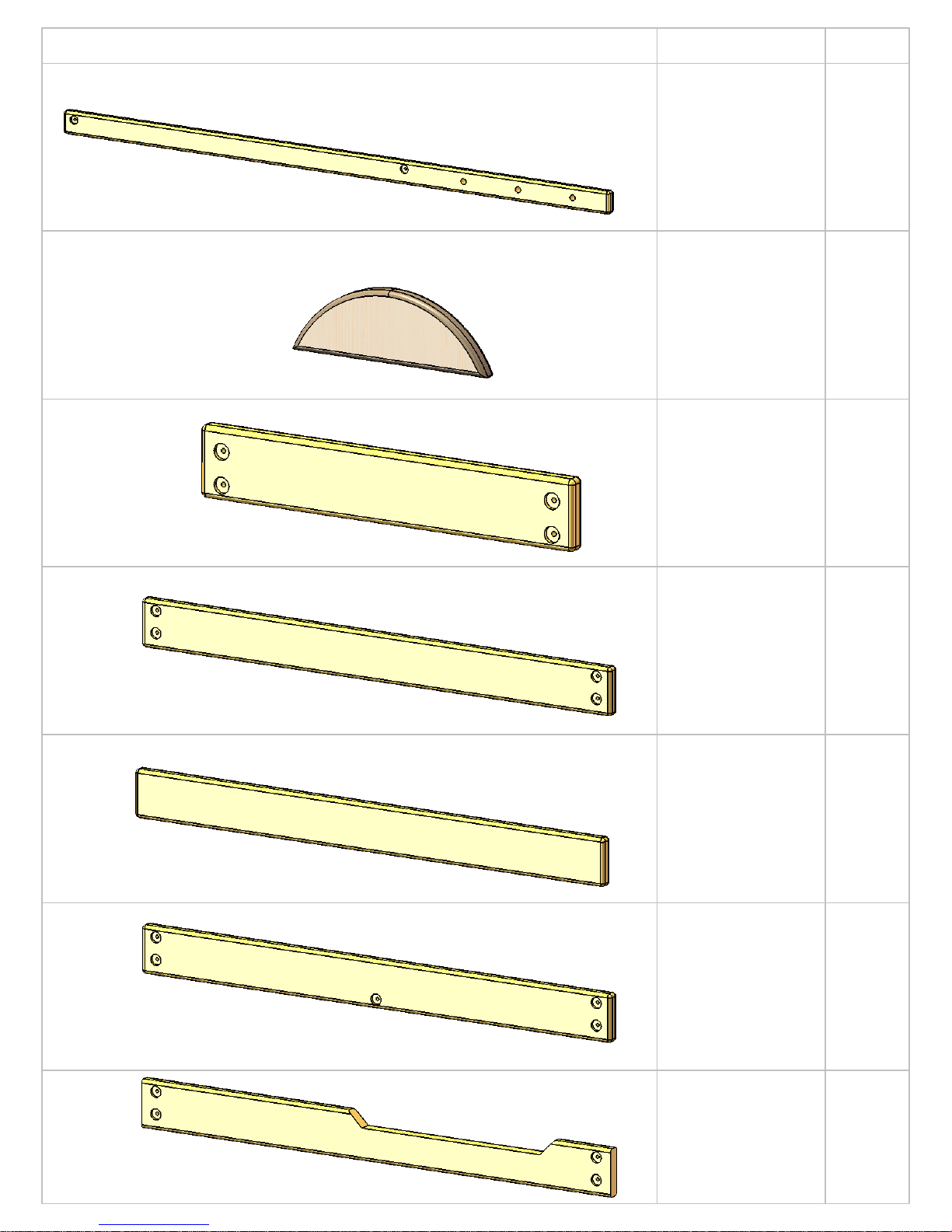
DESCRIPTION
2 X 4 X 30-3/4"
UPPER LEVEL
SIDE TOP PANEL
BOARD (TWO
HOLES OFFSET)
2 X 4 X 31"
LOWER LEVEL
FRONT CENTER
POST
2 X 4 X 34"
SANDBOX
BOARD (TWO
HOLES OFFSET)
QTY.
2
1
2
2 X 4 X 43"
ROOF SUPPORT
2 X 4 X 58"
LOWER DECK
SUPPORT/
SANDBOX
BOARD (TWO
HOLES ON
CENTER)
2 X 4 X 58"
3-HOLE TOP
PANEL BOARD
(THREE HOLES,
TWO OFFSET)
4
LEFT
4
RIGHT
6
1
2 X 4 X 58"
LOWER DECK
SUPPORT
2
PICTURE
24
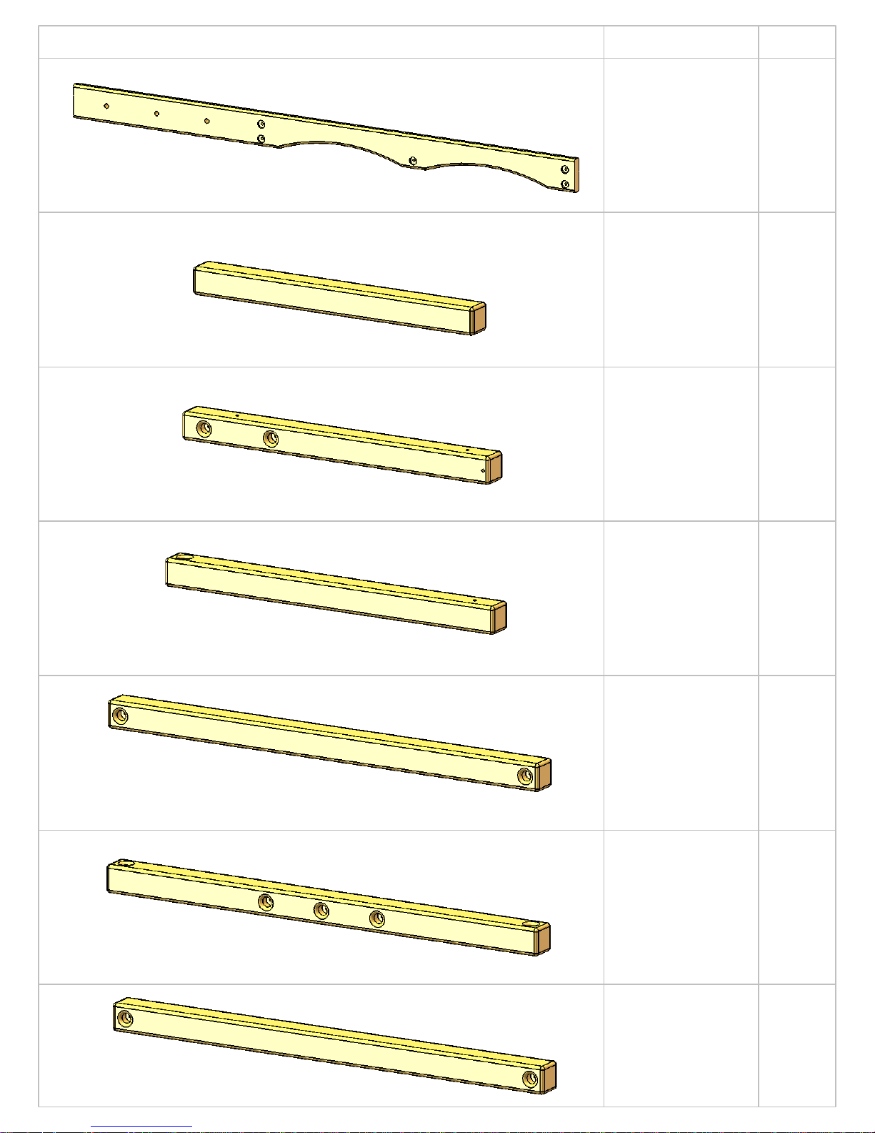
DESCRIPTION
2 X 4 X 58"
PICNIC TABLE
SUPPORT/UPPER
LEVEL STEPS
2 X 4 X 58"
SANDBOX
BOARD/ END
PANEL BOARD
(TWO HOLES
OFFSET)
2 X 4 X 58"
UPPER LEVEL
DECK SUPPORT
(THREE HOLES
ON CENTER)
QTY.
7
4
2
2 X 4 X 60-1/8"
LOWER LEVEL
REAR CENTER
POST
2 X 4 X 66"
LADDER SIDE
2 X 4 X 66"
ROCK WALL
SIDE
1
1
LEFT
1
RIGHT
2
2 X 4 X 88-3/4"
SIDE SANDBOX
BOARD
1
LEFT
1
RIGHT
PICTURE
25
DESCRIPTION
2 X 4 X 90"
ROPE LADDER
RUNNER (5
HOLES, TWO
OFFSET)
2 X 6 X 16"
SUN
2 X 6 X 30-3/4"
UPPER LEVEL SIDE
BOTTOM PANEL
BOARD (FOUR
HOLES OFFSET)
QTY.
1
3
3
2 X 6 X 58"
BOTTOM PANEL
BOARD (FOUR
HOLES OFFSET)
2 X 6 X 58"
PICNIC TABLE
TOP & SEATS
2 X 6 X 58" REAR
BOTTOM PANEL
BOARD (FIVE
HOLES OFFSET)
2
8
1
2 X 6 X 58"
SIDE FACE BOARD
(FOUR HOLES
OFFSET)
1
PICTURE
26
DESCRIPTION
2 X 6 X 90"
ROPE LADDER
SUPPORT (EIGHT
HOLES, 5 OFFSET)
4 X 4 X 37-11/16"
UPPER LEVEL
FRONT CENTER
POST
4 X 4 X 41-5/16"
UPPER LEVEL
LAG POST
QTY.
1
1
2
4 X 4 X 44-1/4"
UPPER LEVEL
REAR CENTER
POST
4 X 4 X 58"
SWING LEG
CROSS-MEMBER
4 X 4 X 58"
SWING BEAM
MOUNT
1
1
1
4 X 4 X 58"
UPPER LEVEL
DECK SUPPORT
1
PICTURE
27
DESCRIPTION
PLASTIC COATED
4 X 4 X 96"
LOWER FRONT
CORNER POST
PLASTIC COATED
4 X 4 X 96"
LOWER REAR
CORNER POST
PLASTIC COATED
4 X 4 X 108"
SWING LEGS
QTY.
2
2
2
PLASTIC COATED
4 X 4 X 120"
UPPER LEVEL
CORNER POST
PLASTIC COATED
4 X 6 X 120"
SWING BEAM
5/4 X 2 X 10"
SMALL RAY
2
1
18
1-3/8 X 1-5/8 X
10-1/2"L TICTAC-TOE
BOARD
2
PICTURE
28
DESCRIPTION
5/4 X 2 X 16"
LARGE RAY
5/4 X 3 X 18-3/4"
LADDER BACK
5/4 X 3 X 23-7/8"
ROCK WALL
CAP
QTY.
3
1
1
5/4 X 3 X 28"
LOWER DECK
PANEL SLAT
5/4 X 3 X 33-1/2"
UPPER DECK
PANEL SLAT
5/4 X 3 X 42"
SUN SUPPORT
13
12
3
5/4 X 4 X 23-3/4"
DECK SPACER
4
PICTURE
29
DESCRIPTION
5/4 X 4 X 51"
DECK SPACER
5/4 X 6 X 23-7/8"
BOTTOM ROCK
WALL BOARD
5/4 X 6 X 23-7/8"
ROCK WALL
BOARD
QTY.
2
1
11
5/4 X 6 X 58"
DECK BOARD
5/4 X 6 X 10"
ROOF SUPPORT
30-3/4" ROOF
PEAK
58" ROOF PEAK
12
4
1
1
COUNT AND ORGANIZE YOUR LUMBER INTO LIKE STACKS (2 X 4, 2 X 6, 4 X 4, 4 X 6, ETC.). THIS WILL
HELP IN IDENTIFYING COMPONENTS AND REDUCE YOUR BUILDING TIME
DESCRIPTIONPICTURE QTY.
30
10' WAVE
SLIDE
1
RAD RIDE
TUBE SLIDE
SWINGS
W/CHAINS
1
2
TRAPEZE
BAR
W/CHAINS
1
 Loading...