

Page 1
MDE-LEDI-NETWORK-IN-4065V1.0
LEDI® NETWORK IN
MODE D’EMPLOI - PAGE 3
USER GUIDE - PAGE 49
Page 2

2
MDE-LEDI-NETWORK-IN-4065V1.0
ATTENTION ! Avant de commencer l’installation de votre matériel, lisez attentivement la section suivante qui décrit les consignes de sécurité à respecter au cours
de l’installation.
L’installation électrique sur laquelle le matériel est raccordé doit être réalisée
conformément à la norme NF C 15-100 .
Cet appareil ne comporte pas d’interrupteur d’alimentation primaire : un dispositif
de coupure (disjoncteur ou interrupteur sectionneur), rapidement accessible, doit
être incorporé dans l’installation de câblage. Ce dispositif doit supporter les valeurs de tension et courant nominales indiquées sur l’appareil.
En Europe : dans le cadre de la protection des individus et de l'environnement,
il vous incombe de vous débarrasser de cet équipement dans un site de collecte
prévu à cet effet (séparément des ordures ménagères). Pour de plus amples
informations, contactez votre revendeur, votre site de collecte ou les autorités
locales compétentes.
Toute modication ou ouverture du produit sans l’accord du SAV entraîne la perte
de la garantie.
Toute opération de maintenance doit être effectuée hors-tension, y compris pour
les systèmes reliés aux éventuelles sorties sur relais.
D’une façon générale, les câbles de puissance (alimentation 220V) et de signaux
(information horaire) ne doivent pas être trop proches les uns des autres, pour
éviter toute perturbation. (garder quelques centimètres de distance)
Gorgy Timing décline toute responsabilité en cas d’accidents ou de dommages
provoqués par une mauvaise utilisation du produit.
Les produits GORGY TIMING sont conformes aux normes : CE, EN 60950, EN 55022,
EN 50024.
CONSIGNES DE SÉCURITÉ IMPORTANTES
Page 3

3
MDE-LEDI-NETWORK-IN-4065V1.0
SOMMAIRE
1. INTRODUCTION ............................................................................................................ 5
1.1.Installation rapide .................................................................................................................. 5
1.1.1. Vériez le contenu du carton .................................................................................... 5
1.1.2. Connectez le produit ................................................................................................. 6
1.2. Congurez votre produit ....................................................................................................... 6
2.1.1. Conguration réseau manuelle ................................................................................. 6
2.1.2. Conguration des cartes de sortie ............................................................................ 7
1.3. Généralités ........................................................................................................................... 7
1.3.1. Principes de la synchronisation ................................................................................ 7
A/ Principes de la correction d’horloge ......................................................................... 7
B/ Dialogue réseau ....................................................................................................... 9
C/ Travailler avec plusieurs serveurs ............................................................................ 9
1.3.2. Le logiciel client NTP .............................................................................................. 10
2. CONFIGURATION COMPLÈTE ...................................................................................11
2.1. Conguration réseau ...........................................................................................................11
2.1.1. Conguration par défaut ..........................................................................................11
2.1.2. Changement des paramètres réseau ......................................................................11
2.1.3. Intégration dans votre réseau ................................................................................. 13
2.2. Conguration des cartes de sortie ...................................................................................... 14
2.2.1. Introduction ............................................................................................................. 14
2.2.2. Conguration par défaut ......................................................................................... 14
2.2.3. Changer les réglages ............................................................................................. 14
2.2.4. Paramètres génériques .......................................................................................... 15
A/ Fuseau horaire ....................................................................................................... 15
B/ Politique de changement d’heure (DST : Day Saving Time) .................................. 15
C/ Désactivation des sorties ....................................................................................... 15
3. INTERFACE FACE AVANT .......................................................................................... 16
3.1. Conditions au démarrage ................................................................................................... 16
3.2. Afchage de l’heure ............................................................................................................ 17
3.4. Conditions d’alarmes mineures .......................................................................................... 18
3.5. Conditions d’alarmes majeures .......................................................................................... 18
4. INTERFACE WEB ........................................................................................................ 19
4.1. Présentation ....................................................................................................................... 19
4.2. Description de l’interface WEB ........................................................................................... 20
4.2.1. Ecran Principal ....................................................................................................... 20
4.2.2. Réglages standards ................................................................................................ 21
4.2.3. Conguration SNMP .............................................................................................. 24
4.2.4. Conguration NTP ................................................................................................. 26
4.2.5. Conguration des sorties ........................................................................................ 28
5. INTERFACE SNMP ..................................................................................................... 30
5.1. Présentation ....................................................................................................................... 30
5.1.1. Structure de la MIB privée pour le LEDI Network IN .............................................. 31
FRANCAIS
Page 4
4
MDE-LEDI-NETWORK-IN-4065V1.0
6
ANNEXE A – CONNEXIONS ........................................................................................... 35
1. Connexion pour tous les produits .......................................................................................... 35
1.1. Produits 230V et 115V AC (type ‘0’) .......................................................................... 35
1.2. 18/72V DC product (type ‘9’) ..................................................................................... 35
2. Sortie pour carte type ‘B’ (sortie double AFNOR/IRIG-B NFS87500) .................................... 36
3. Sortie pour carte type ‘A’ (ASCII+TOP) ................................................................................. 37
ANNEXE B – FORMAT DU CODE DE SORTIE .............................................................. 39
1. Carte Type ‘A’ (sortie ASCII+TOP) ......................................................................................... 39
2. Carte type ‘B’ (AFNOR/IRIG-B NFS87500) ........................................................................... 40
2.1. Format de la trame .................................................................................................... 40
2.2. Encodage des bits ..................................................................................................... 41
ANNEXE C – CARACTÉRISTIQUES .............................................................................. 42
1. Dimensions ............................................................................................................................ 42
2. Spécications électriques ...................................................................................................... 42
3. Autres spécications .............................................................................................................. 42
ANNEXE D – GUIDE DES CODES PRODUITS .............................................................. 43
1. Localisation de l’étiquette ...................................................................................................... 43
2. Informations de l’étiquette ..................................................................................................... 43
ANNEXE E – DOCUMENTS COMPLÉMENTAIRES ....................................................... 44
Page 5

5
MDE-LEDI-NETWORK-IN-4065V1.0
Ce document est le manuel d’utilisation pour le LEDI Network IN. Ce produit est un client
NTP. L’objectif de cet appareil est de synchroniser divers équipements en utilisant le temps
de référence fournit par un ou plusieurs serveurs NTP. Ce produit peut être vu comme une
sorte de convertisseur qui traduit un « signal NTP » en signaux de synchronisation tradi-
tionnels (ASCII+TOP, AFNOR, IRIG-B par exemple).
L’utilisation du LEDI Network IN pour la synchronisation a plusieurs avantages :
Vous pouvez utiliser l’architecture réseau installée grâce au protocoles ►
Ethernet+TCP/IP biens connus .
L’installation est simple. ►
Une conguration et un diagnostique à distance aisée . ►
Le produit est un rack 19” 1U qui s’intègre facilement à votre installation. ►
En utilisant le LEDI Network IN avec un serveur Gorgy Timing, vous facilitez fortement
l’installation et l’utilisation.
Allez directement à la section 1.1. pour l’installation rapide ☛
1.1. INSTALLATION RAPIDE
Cette partie contient les informations élémentaires pour l’installation du LEDI Network IN.
Vous trouverez des informations complémentaires dans la partie 3.
1.1.1. Vériez le contenu du carton
Le carton doit contenir les éléments suivants:
Le produit lui-même : un rack 19” 1U. ►
• Le nom de ce produit est LEDI NETWORK IN qui est écrit sur la façade avant
du rack.
• Une étiquette placée sur la face arrière ou le dessus du produit donne l’identi-
cation du produit. Il doit être écrit 9257/opt (où opt dépend des cartes de sortie
– voir Annexe D – Guide des codes produits).
Un câble d’alimentation (versions 220V~ et 115V~ uniquement). ►
Un câble réseau. ►
Un CDROM contenant les outils d’installation et de gestion. ►
Contactez votre revendeur s’il manque un des éléments ☛
1. INTRODUCTION
FRANCAIS
Page 6

6
MDE-LEDI-NETWORK-IN-4065V1.0
1.1.2. Connectez le produit
Il est fortement conseillé de noter le numéro de série (inscrit sur l’étiquette d’identi- ►
cation), la localisation et un bref descriptif du produit. Vous pouvez utiliser pour cela
la che dans Annexe E – Documents complémentaires.
Connectez les sorties de synchronisation à vos équipements (voir Annexe A – ►
Connexions pour plus d’informations).
Connectez le LEDI Network IN à votre réseau en utilisant le câble réseau fournit. ►
Branchez le LEDI Network IN à une source de courant en utilisant le câble d’alimen- ►
tation s’il est fournit.
Votre système doit fonctionner immédiatement si vous utilisez un ou des serveurs
NTP Gorgy Timing et qu’il y a un serveur DHCP sur votre réseau. Après une étape
d’apprentissage de 3 minutes, le LEDI Network IN active ses sorties et commence à
générer du temps UTC.
Cependant, Gorgy Timing vous recommande d’inscrire pour chaque produit son emplacement physique. Ceci est possible grâce au logiciel GTNetMng fournit sur le CDROM.
Pour plus d’informations, voir la partie 31.2.
1.2. CONFIGUREZ VOTRE PRODUIT
2.1.1. Conguration réseau manuelle
Les produits NTP Gorgy Timing sont congurés en usine pour récupérer automatiquement
une adresse IP. Deux mécanismes sont utilisés :
1.
Si un serveur DHCP est présent sur votre réseau, le produit récupère une adresse
automatiquement. Ceci assure la compatibilité de l’adresse IP avec votre réseau.
2. Si aucun serveur DHCP n’est présent, le produit prend automatiquement une
adresse IP grâce au mécanisme AutoIP. Dans ce cas, l’adresse sera 169.254.x.y
(où x et y sont compris entre 0 et 255). Si le serveur et le client ont démarré tous
deux dans ce mode, il devraient fonctionner ensemble correctement, mais leurs
adresses IP seront peut-être incompatibles avec d’autres appareils présents sur
le réseau.
1
1/ Il se peut par exemple que vous n’ayez pas la possiblité de congurer le LEDI Network IN par un navigateur WEB.
Page 7

7
MDE-LEDI-NETWORK-IN-4065V1.0
L’identicateur DHCP par défaut est CRnnnnnn (nnnnnn est le numéro de série du
produit).2 Vou pouvez changer cet identicateur grâce au logiciel GtNetMng, ou à tra-
vers l’interface WEB, comme décrit dans les parties 31.2 et 52.2.
Si vous n’avez pas de serveur DHCP ou que vous souhaitez congurer vous-même les
paramètres réseau, utilisez l’outil GTNetMng sur le CDROM pour changer les paramètres réseau. Veuillez vous référer à la partie 31.2 pour plus d’informations.
N’hésitez pas à contacter votre administrateur réseau ☛
pour la conguration du LEDI Network IN.
Il peut vous aider à optimiser votre installation réseau
2.1.2. Conguration des cartes de sortie
Par défaut, toutes les cartes de sortie fournissent l’heure UTC. L’heure reçue du serveur NTP est directement envoyée en sortie.
Chaque carte peut-être congurée pour fournir plusieurs heures locales. Cette conguration est effectuée au travers d’un navigateur WEB (voir la partie 32).
1.3. GÉNÉRALITÉS
Cette partie décrit les concepts généraux du produit LEDI Network IN. Elle permet de comprendre le fonctionnement du produit dans différentes circonstances.
Le logiciel NTP client est le cœur du LEDI Network IN. Il effectue toute la synchronisation,
la gestion du matériel et fournit les informations pour l’interface WEB et pour le protoco-
le SNMP.
1.3.1. Principes de la synchronisation
A/ Principes de la correction d’horloge
Le but de la synchronisation est que deux horloges indiquent la même heure. Dans le
cas d’une synchronisation basée sur le NTP, l’horloge du LEDI Network IN doit avoir la
même heure que celle du serveur NTP.
2/ Certains serveur DHCP peuvent enregistrer le nom DHCP dans le DNS. Dans ce cas, vous pouvez accéder au
LEDI Network IN directement par son nom DHCP au lieu de son adresse IP.
1. INTRODUCTION
FRANCAIS
Page 8
8
MDE-LEDI-NETWORK-IN-4065V1.0
Pour réaliser cette synchronisation, le logiciel client NTP compare en permanence les
deux horloges et calcule les informations suivantes :
Le décalage : ►
C’est la différence entre l’heure de l’horloge serveur, et celle de l’horloge cliente.
Par exemple, si l’horloge serveur indique2:10:13 et que l’horloge cliente indique
2:11:14, alors le décalage est –1 :01 .
La dérive : ►
C’est la différence de fréquence entre les deux horloges. Quand la dérive est nonnulle et sans correction d’horloge, le décalage entre les horloges augmente ou diminue, en fonction du signe de la dérive.
3
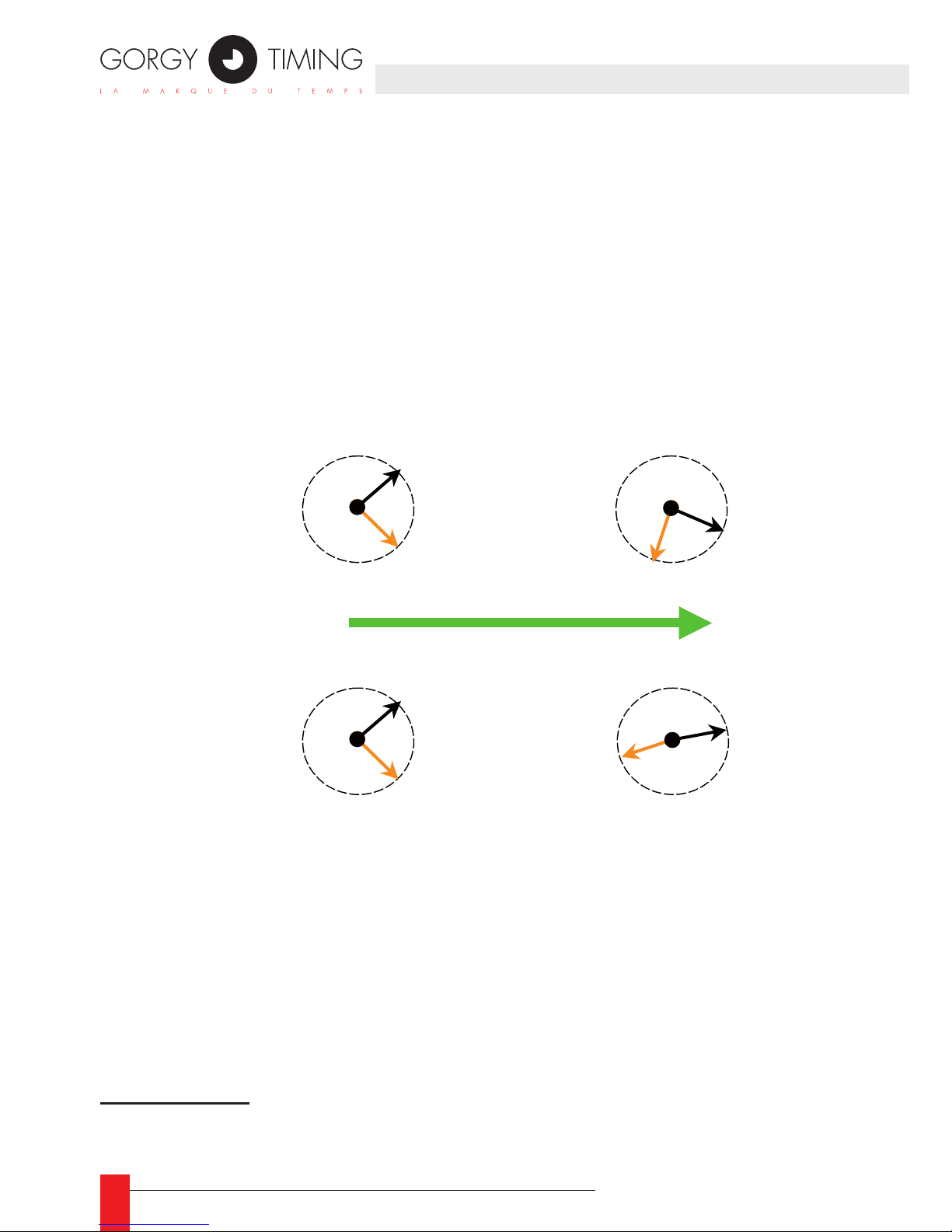
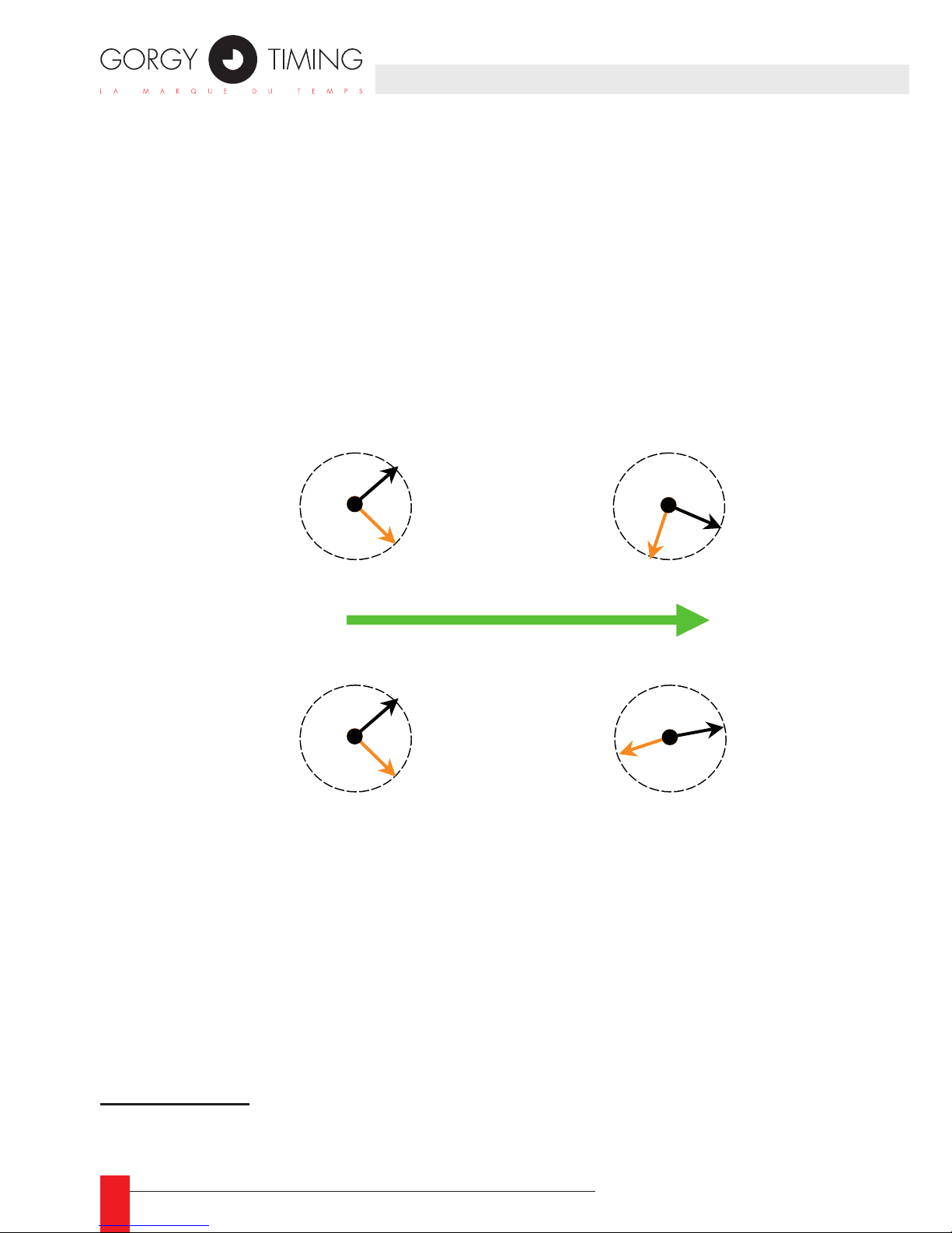
Le schéma suivant montre l’évolution des deux horloges avec et sans décalage :
L’objectif de la synchronisation d’un client NTP sur un serveur NTP est de réduire autant
que possible le décalage et la dérive. La précision et la stabilité de l’horloge du client
sont étroitement liés à l’efcacité de ce processus de réduction.
3/ La présence d’une dérive a plusieurs causes possibles. Généralement, elle est due à la différence de température entre les deux horloges.
Heure serveur
Heure client
Heure serveur
Heure client
Heure serveur
Heure client
Heure serveu
r
Heure client
Dérive nulle
Dérive constante
Evolution dans le temps
Page 9

9
MDE-LEDI-NETWORK-IN-4065V1.0
B/ Dialogue réseau
Le décalage et la dérive réel de l’horloge du LEDI Network IN par rapport à celle du
serveur NTP sont estimés d’après un décalage mesuré. Ce décalage est calculé en
soustrayant la date de l’horloge client à celle de l’horloge serveur.
Périodiquement, le client estime le décalage actuel d’après le serveur. Cette mesure
est effectuée grâce à un mécanisme de transmission de messages, tel qu’on peut le
voir ci-dessous :
Sur un LAN, il suft de quelques millisecondes entre la requête de la date par le client,
et le moment où il reçoit la réponse. Ce retard est dû au délai de transmission sur le
réseau. Il peut varier en fonction de la charge du réseau ou de la charge du serveur
NTP. Plus grave, le temps de transmission du client au serveur n’est généralement pas
le même que du serveur au client.
En réalité, sur une grande période de temps, la somme des différences entre les délais
de transmission client-serveur et serveur-client vaut zéro. L’algorithme du client NTP
inclue dans le LEDI Network IN est conçu pour compenser les délais de transmission
et pour moyenner les mesures.
C/ Travailler avec plusieurs serveurs
Le logiciel client NTP a le possibilité de travailler avec plusieurs serveurs NTP (jusqu’à 3). Quand un serveur ne répond pas, répond trop lentement ou n’envoie pas sufsamment de réponses, le logiciel client NTP utilise un autre serveur.
Demande l’heure
du serveur
Reçoit la réponse
Coté client
Coté server
Réseau
Envoie l’heure serveur
actuelle
1. INTRODUCTION
FRANCAIS
Page 10

10
MDE-LEDI-NETWORK-IN-4065V1.0
1.3.2. Le logiciel client NTP
Etats du logiciel NTP
Voici les différents états du logiciel client NTP :
Voici la signication de ces états:
Démarrage : ►
Le logiciel démarre, il initialise et vérie le matériel si besoin .
Auto-détection : ►
L’autodétection des serveurs est activée. Le client essaie de trouver des serveurs
Gorgy Timing. Il faut détecter au moins un serveur pour quitter cet état .
Apprentissage : ►
Le logiciel client NTP a détecté un ou plusieurs serveurs Gorgy Timing (auto-dé-
tection activée) ou travaille avec des serveurs congurés. Dans cet état, le logiciel
étudie les propriétés du réseau. Jusqu’à 3 minutes sont nécessaires pour terminer
cette étape.
Travail : ►
Fonctionnement normal, le client NTP évalue en permanence son décalage et sa
dérive par rapport au serveur:
Commutation : ►
Comme trop peu de réponses sont reçues du serveur actuel, le client essaie un
autre serveur. Attention ! Le LEDI Network IN peut fonctionner seulement un certain temps sans synchronisation. Passé un certain délai, il désactive toutes les cartes de sortie et retourne à l’état de démarrage.
4
4/ L’autonomie du LEDI Network IN dépend du temps écoulé depuis son démarrage, les caractéristiques du
réseau, et de la précision désirée.
Démarrage
Auto-détection
Apprentissage
Travail
Commutation
Erreur
Apprentissage
du milieu
Recherche les
serveurs .
Activer les sorties
Pas de réponse
Commutation OK
Apprentissage
du milieu
1. INTRODUCTION
Page 11

11
MDE-LEDI-NETWORK-IN-4065V1.0
2. CONFIGURATION COMPLÈTE
2
Cette partie contient les informations pour la conguration complète du produit. Elle
doit être utilisée pour la conguration ne du réseau, et pour l’activation des cartes
de sortie.
2.1. CONFIGURATION RÉSEAU
2.1.1. Conguration par défaut
Le LEDI Network IN est conguré pour récupérer automatiquement une adresse IP
d’un serveur DHCP. Au démarrage, le produit émet une requête DHCP pour obtenir une
adresse IP. Cette requête contient un identicateur DHCP. Deux cas se présentent :
Si un serveur DHCP est installé sur le réseau, il enregistre l’identicateur DHCP et ►
renvoie une adresse IP. Le LEDI Network IN commence alors à travailler avec cette
adresse.
Si aucun serveur DHCP n’est installé, le LEDI Network IN utilise automatiquement ►
une adresse IP par défaut, de type 169.254.x.y (avec x et y compris entre 0 et 255).
L’identicateur DHCP par défaut du produit est CRnnnnnn, avec nnnnnn le numéro de
série sur 6 chiffres. Le numéro de série est indiqué sur d’étiquette d’identication sur le
dessus ou sur le dessous du produit.
L’identicateur SNMP par défaut du produit (visible à partir d’un navigateur SNMP (voir
partie 6) ou d’un navigateur WEB) est LediNtpRacknnnnnn, avec nnnnnn le numéro
de série sur 6 chiffres.
2.1.2. Changement des paramètres réseau
Utiliser le logiciel GTNetMng fourni sur le CD-ROM pour congurer votre appareil:
Insérer le CDROM dans le lecteur. Lancer le logiciel GTNetMng localisé dans le ►
répertoire Common\Conguration
5
5/ Par exemple, si votre lecteur CD a la lettre E:, le logiciel GTNetMng se trouve en
E:\Common\Conguration\GTNetMng.exe
FRANCAIS
Page 12
12
MDE-LEDI-NETWORK-IN-4065V1.0
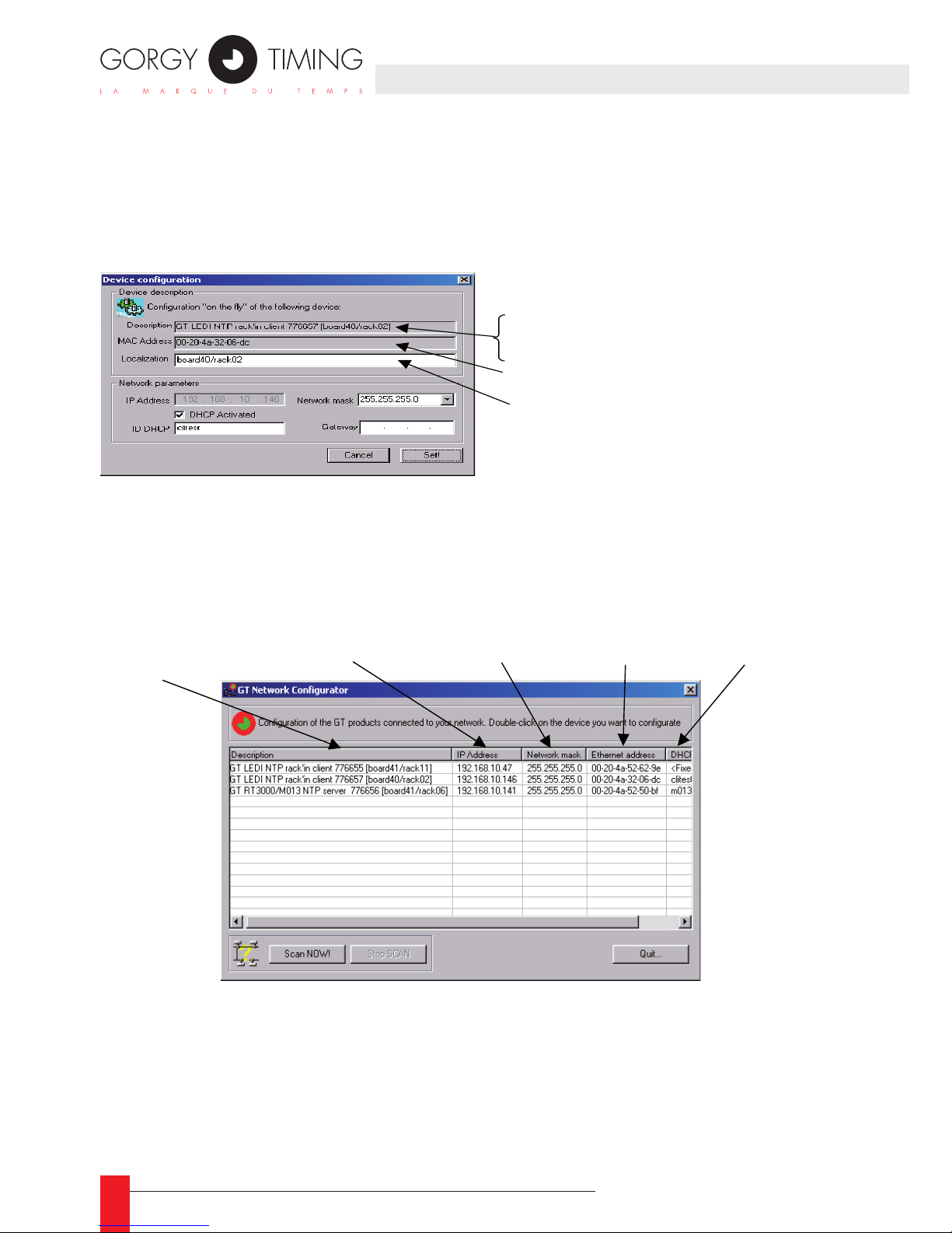
L’outil ► GTNetMng afche automatiquement les produits Gorgy Timing installés sur
votre réseau. Chaque ligne contient des informations sur un produit connecté, comme montré ci-dessous:
Double-cliquez sur la ligne du produit que vous souhaitez congurer. La fenêtre ►
suivante s’afche :
Entrez les paramètres réseau et la localisation physique et cliquez sur le bouton ►
Set!.
Nom, numéro de
série et localisation
Adressse IP actuelle
Masque de sousréseau
Identificateur DHCP
Adresse MAC
Nom de l’appareil (
GT LEDI NTP in’rack client
)
Numéro de série (
776657
)
Localisation (
board40/rack02
)
Adresse Ethernet (MAC) de l’appareil
Localisation du produit
Page 13

13
MDE-LEDI-NETWORK-IN-4065V1.0
2.1.3. Intégration dans votre réseau
Vous n’avez à changer aucun réglage réseau pour les cas suivants :
Vous avez un serveur DHCP et sufsamment d’adresses IP réservées pour le produit. ►
Vous n’avez pas de serveur DHCP mais vous n’avez pas besoin d’accéder à l’appa- ►
reil par son interface WEB ou SNMP. Dans ce cas, le mécanisme AutoIP affectera
automatiquement une adresse IP, mais cette adresse sera probablement incompatible avec votre réseau.
Certains serveurs DHCP ont la capacité d’enregistrer l’appareil dans le DNS. Dans ce
cas, le nom enregistré est l’identicateur DHCP. Vous pouvez ensuite accéder à l’appareil au travers d’un navigateur WEB ou SNMP. Par exemple, si vous donnez comme
nom DHCP inrack3 à votre LEDI Network IN, il vous suft de taper inrack3 dans le
champs d’adresse de votre navigateur WEB.
Si vous avez plusieurs produits connectés à votre installation, il est fortement recommandé de suivre les étapes suivantes :
Utilisez le document fourni dans Annexe E – Documents complémentaires (Vue ►
résumée de l’installation) et inscrivez le numéro de série et la localisation physique
pour chaque produit pendant l’installation et la connection.
Lancez GtNetMng sur un PC connecté sur le même réseau que celui du produit. ►
Tous les produits GT devraient apparaître avec leurs numéros de série. Entrez le
numéro de série et la localisation en utilisant le document rempli à l’étape précédente.
Vous pouvez garder ce document pour une prochaine utilisation. ►
Vous trouverez le document Vue résumée de l’installation au format ☛
WORD sur le CD-ROM, dans le répertoire English\LEDI Network IN\docs\
installation.doc.
2. CONFIGURATION COMPLÈTE
FRANCAIS
Page 14

14
MDE-LEDI-NETWORK-IN-4065V1.0
2.2. CONFIGURATION DES CARTES DE SORTIE
2.2.1. Introduction
Votre LEDI Network IN est fourni avec jusqu’à 4 cartes de sortie. Chaque carte de sortie
est étroitement synchronisée sur le code horaire NTP reçu du serveur NTP. Chaque
carte agit comme une sorte de traducteur qui reçoit l’heure du logiciel NTP et fournit un
code horaire spécique.
Il existe 2 types de cartes:
ASCII+TOP (carte type ‘A’). ►
AFNOR (carte type ‘B’). ►
Vous pouvez librement utiliser et copier le tableau Conguration des appareils dans
l’Annexe E – Documents complémentaires.
2.2.2. Conguration par défaut
Quand vous recevez ce produit Gorgy Timing, toutes les cartes de sortie sont congurées pour fournir l’heure UTC et le temps est constant toute l’année (pas de change-
ment d’heure été/hiver, ou DST Day Saving Time). L’afcheur en face avant est géré
comme une carte de sortie et peut-être congurée de la même manière.
2.2.3. Changer les réglages
Ouvrez le site WEB du LEDI Network IN (voir partie 5). Cliquez sur le bouton .
La conguration actuelle de votre produit apparaît sur l’écran (montré ci-dessous pour
le modèle 9257/ A):
Dans cet écran, vous pouvez régler chaque carte indépendamment (voir la partie 52.5).
Quand vous avez changé les réglages, cliquez sur le bouton .
La modication devrait apparaître immédiatement à la sortie ou à l’écran.
Page 15

15
MDE-LEDI-NETWORK-IN-4065V1.0
2.2.4. Paramètres génériques
Toutes les cartes de sorite et l’afcheur peuvent être congurés indépendamment. Le
fuseau horaire et la politique de changement d’heure (DST) peuvent être réglées. A
l’exception de l’afcheur, toutes les cartes de sortie peuvent être désactivées.
A/ Fuseau horaire
Le fuseau horaire est un décalage de temps qui peut être ajouté ou retiré du temps
reçu grâce au protocole NTP (qui est en heure UTC) pour générer l’heure locale.
Par exemple, en France, l’heure locale est GMT + 1:00. Si vous souhaitez qu’une
carte génère l’heure locale, utilisez l’interface WEB et réglez le décalage à GMT
+1:00.
B/ Politique de changement d’heure (DST : Day Saving Time)
En plus du fuseau horaire, beaucoup de pays appliquent leur politique de changement d’heure. L’année est ainsi coupée en 2 parties : en été, 1 heure est ajoutée
au temps (après la correction du fuseau horaire), en hiver seule est appliquée la
correction du fuseau horaire.
N’oubliez pas de sélectionner le pays approprié dans l’interface WEB. ☛
C/ Désactivation des sorties
Vous pouvez également désactiver la sortie d’une care si besoin. La désactivation
a les effets suivants :
Pour la carte ASCII + TOP, la trame de temps n’est plus générée, et la sortie TOP ►
est à l’état ouvert (relais et collecteur ouvert).
Pour la sortie AFNOR, la porteuse n’est plus modulée. ►
2. CONFIGURATION COMPLÈTE
FRANCAIS
Page 16
16
MDE-LEDI-NETWORK-IN-4065V1.0
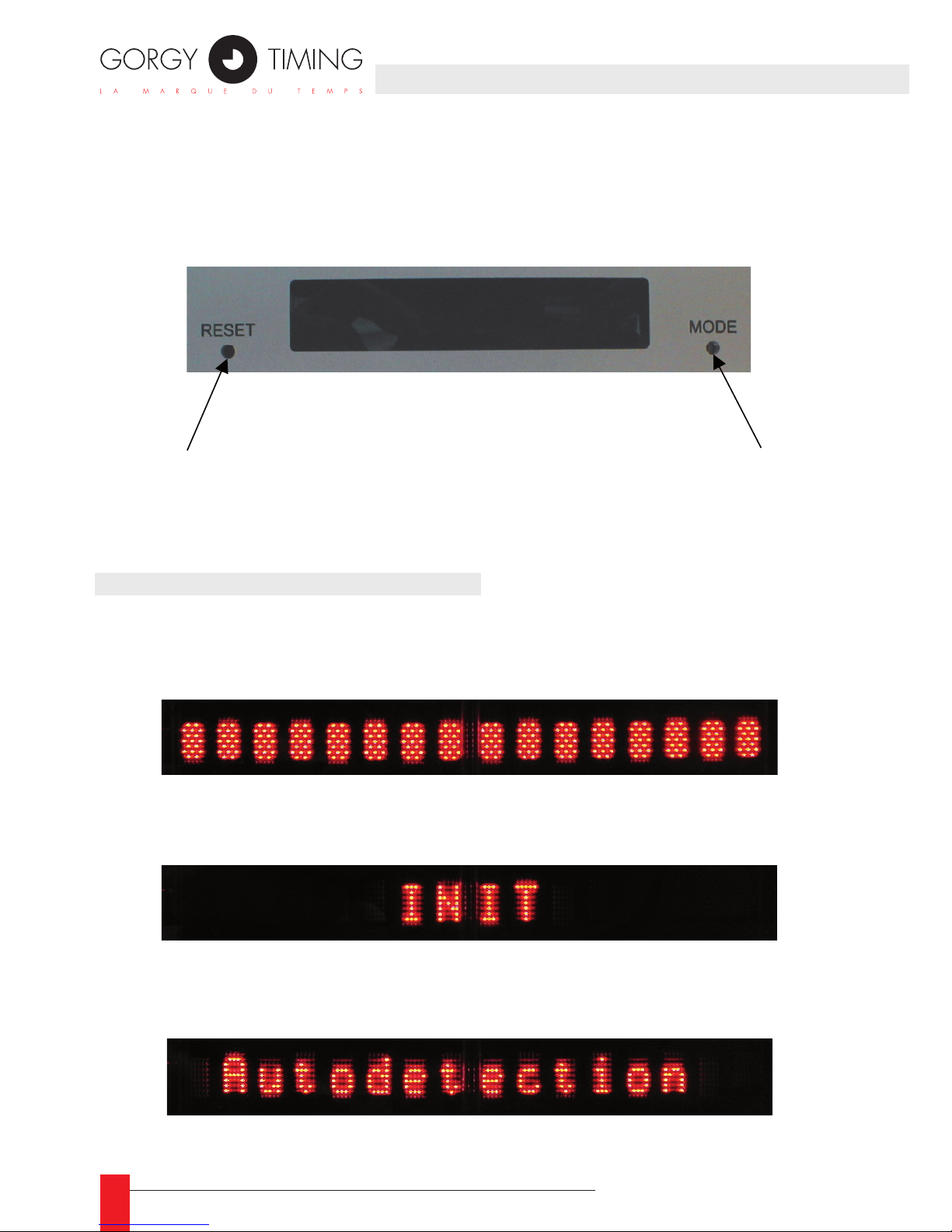
L’interface de l’écran en face avant peut afcher jusqu’à 16 caractères. Deux boutons vous permettent soit d’afcher la conguration, soit d’effectuer un redémarrage global. L’afcheur est utilisé par le LEDI Network IN pour montrer l’heure actuelle
et les différentes conditions d’alarmes.
3.1. CONDITIONS AU DÉMARRAGE
Au démarrage, l’heure et la date du LEDI Network IN ne sont pas valides et ne sont dons
pas afchés. Ainsi, vous voyez les messages suivant :
Quand l’appareil démarre, tous les points de l’afcheur sont allumés. ►
Durant l’initialisation du matériel, le texte suivant est afché: ►
Si aucun serveur n’est conguré par l’utilisateur, le LEDI Network IN essaie de dé- ►
tecter les serveurs GT, et afche ce message:
Redémarrer le LEDI
NTP in’rack
Commuteraffichage
heure UTC/heure locale
Page 17
17
MDE-LEDI-NETWORK-IN-4065V1.0
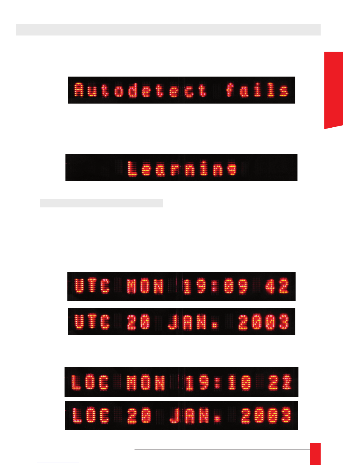
Si l’étape d’auto-détection échoue, le message suivant apparait, jusqu’à ce qu’un ►
serveur GT soit disponible sur réseau:
S’il y a au moins un serveur GT ou que l’utilisateur a conguré manuellement les ►
serveurs, le LEDI Network IN entre dans son étape d’apprentissage et afche le
texte suivant :
3.2. AFFICHAGE DE L’HEURE
Quand aucune alarme n’est activée et que le LEDI Network IN est correctement synchronisé sur un serveur, l’heure actuelle du serveur est afchée en permanence. L’écran afche
alternativement l’heure et la date comme montré ci-dessous :
• Quand l’afcheur est conguré pour montrer l’heure UTC, les informations suivantes sont afchées alternativement :
• Quand l’afcheur est conguré pour montrer l’heure locale, les informations suivantes sont afchées alternativement :
3. INTERFACE FACE AVANT
FRANCAIS
Page 18
18
MDE-LEDI-NETWORK-IN-4065V1.0
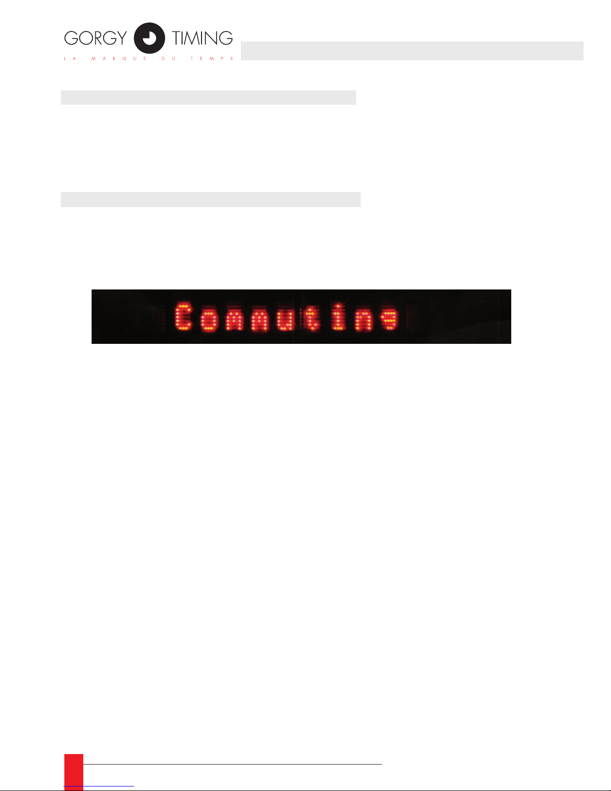
3.4. CONDITIONS D’ALARMES MINEURES
L’unique alarme mineure indique que le serveur actuellement utilisé pour la synchronisa-
tion ne répond pas (ou pas correctement). Dans ce cas, le LEDI Network IN essaie d’autres
serveurs, et l’afcheur indique alternativement l’heure (comme décrit dans la partie précé-
dente) et les informations suivantes :
3.5. CONDITIONS D’ALARMES MAJEURES
Il existe deux alarmes différentes:
Si la LEDI Network IN ne peut pas contacter un serveur NTP, il afche en alternance ►
le message suivant et l’heure et la date:
Si aucun serveur NTP n’a été trouvé au bout d’un certain temps, le LEDI Network ►
IN désactive ses sorties et afche le message clignotant suivant:
Page 19

19
MDE-LEDI-NETWORK-IN-4065V1.0
4.1. PRÉSENTATION
Le LEDI Network IN peut être conguré et supervisé à travers une inerface WEB. Cette
interface vout permet de :
gérer les paramètres réseau. ►
gérer les paramètres SNMP. ►
gérer et diagnostiquer le logiciel client NTP lui-même. ►
gérer et diagnostiquer les cartes de sortie. ►
Chaque LEDI Network IN intègre son propre serveur WEB qui délivre une page WEB. Ce
site WEB est un applet JAVA . si besoin une JVM (Java Virtual Machine) vous est fournie
sur le CD-ROM, dans le répertoire Common\JAVA.
Pour accéder au site WEB, entrez l’adresse du LEDI Network IN dans le champs d’adresses de votre navigateur WEB (comme ci-dessous), et appuyez sur Entrée.
6
Le chargement de l’applet JAVA prend environ 20 secondes. Si le chargement échoue, il
peut y avoir plusieurs raison à cela :
1. l’adresse IP n’est pas valide.
2. un problème sur le réseau 7 empèche votre PC de se connecter au LEDI Network IN.
3. vous n’avez pas de JVM (Java Virtual Machine) installée sur votre PC.
Dans les deux premiers cas, vériez l’adresse IP de votre LEDI Network IN et votre conguration réseau. Dans le dernier cas, vous devez installer la JVM (voir Common\JAVA sur
le CDROM).
6: Si vous avez conguré votre LEDI Network IN en mode DHCP et que votre serveur enregistre automatiquement
l’identicateur DHCP dans le DNS, vous pouvez entrer le nom DHCP au lieu de l’adresse IP
7/ Vériez en particulier la conguration de votre navigateur WEB.
4. INTERFACE WEB
FRANCAIS
Page 20
20
MDE-LEDI-NETWORK-IN-4065V1.0
4.2. DESCRIPTION DE L’INTERFACE WEB
4.2.1. Ecran Principal
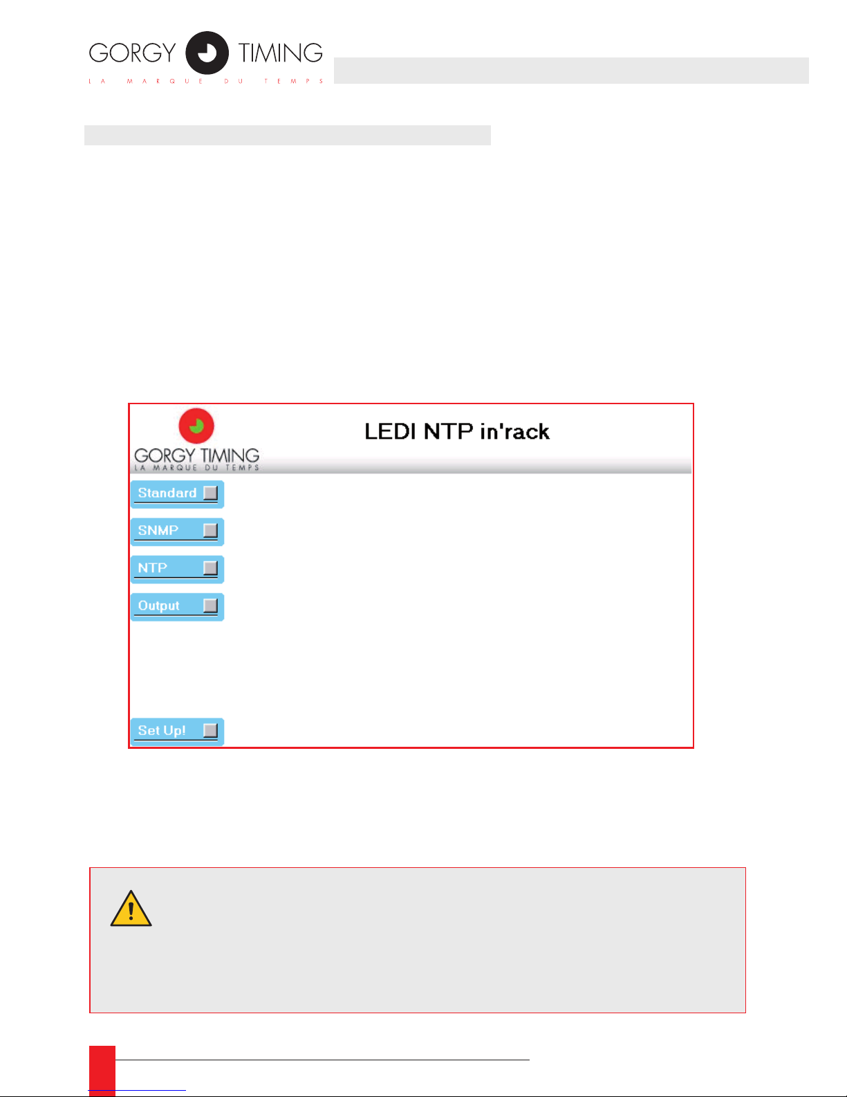
Voici l’écran qui doit apparaître lorsque vous accédez au sit WEB du LEDI Network IN.
Les quatre premiers boutons à gauche de l’écran permettent d’accéder aux panneaux
suivants:
1. Standard: informations concernant le produit et conguration des paramètres ré-
seau. Voir la partie 2.2.
2. SNMP: conguration des paramètres SNMP.
3. NTP: diagnostic et conguration du comportement du logiciel NTP.
4. Output: diagnostic et conguration des cartes de sortie et de l’afcheur.
Le bouton Set Up! rafraichit instantanément la conguration du LEDI Network IN avec
les nouveaux paramètres entrés. Ces paramètres sont alors stockés en permanence
dans une EEPROM.
ATTENTION. La modication de certains paramètres nécessitent le
redémarrage du LEDI Network IN. Si vous changez ces paramètres
et cliquez sur le bouton Set Up!, le LEDI Network IN redémarre avec
les nouveaux paramètres et il faut attendre 3 minutes avant que les
sorties ne soient réactivées.
Page 21
21
MDE-LEDI-NETWORK-IN-4065V1.0
4.2.2. Réglages standards
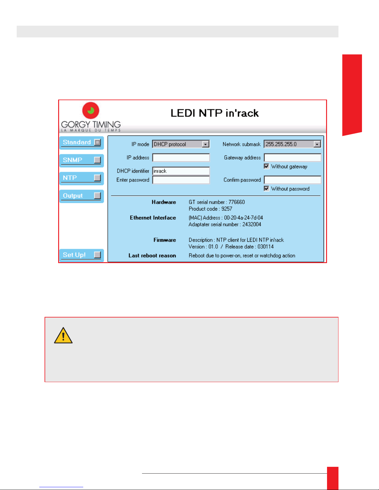
Lorsque vous cliquez sur le bouton Standard, les paramètres réseau et les informa-
tions sur le produit sont afchés ainsi :
En haut, vous pouvez contrôler les paramètres réseau et le mot de passe WEB. En bas
se trouvent des informations sur le produit.
PARAMÈTRES RÉSEAU
Voici les différents paramètres:
IP mode ►
Indique si le LEDI Network IN fonctionne en adresse IP xe (entrée dans le champs
IP address) ou avec le protocole DHCP (l’identicateur DHCP est entré dans le
champs DHCP identier).
ATTENTION. Si vous cliquez sur Set Up! Après avoir changé un ou
plusieurs paramètres réseau, le LEDI Network IN doit redémarrer
pour utiliser ces nouveaux paramètres. Pendant le redémarrage, et
3 minutes après, les sorteis sont désactivées.
4. INTERFACE WEB
FRANCAIS
Page 22

22
MDE-LEDI-NETWORK-IN-4065V1.0
IP address ►
Indique l’adresse IP affectée au réseau. Une adresse IP est composée de 4 numéros séparés par un point. Chaque numéro s’étend de 0 à 255.
DHCP identier ►
Identicateur utilisé quand le LEDI Network IN est conguré en mode DHCP. Il est
composé d’au maximum 8 lettres. Sa valeur par défaut est CRnnnnnn (où nnnnnn
est le numéro de série sur 6 chiffres).
Network submask ►
Indique la taille du réseau que vous utilisez. Par exemple, un masque se sousréseau de 255.255.255.0 indique que seul le dernier numéro de l’IP change (dans
l’exemple ci-dessus, l’adresse dans le réseau peut varier entre 192.168.10.1 à
192.168.10.254)8.
Gateway address ►
Si vous voulez que le LEDI Network IN communique avec d’autres appareils en dehors du réseau local, vous devez indiquer une passerelle (gateway) qui sera utilisée
pour sortir du réseau local.
Without gateway ►
Cochez cette case si vous n’avez pas de passerelle sur votre réseau ou que vous
ne souhaitez pas l’utiliser.
INFORMATIONS SUR LE PRODUIT
Voici une description de la zone d’informations sur le produit::
Hardware ► GT serial number
Afche le numéro de série Gorgy Timing du produit. C’est un numéro à
6 chiffres qui doit être identique à celui collé sous ou dernière le rack .
Hardware ► Product code
Afche le code de base Gorgy Timing du produit sans option (9257 pour un LEDI
Network IN).
Ethernet Interface ► (MAC) Address
Indique l’adresse MAC de l’interface Ethernet du LEDI Network IN.
Ethernet Interface ► Adapter Serial number
Indique le numéro de série de l’interface Ethernet du LEDI Network IN. Cette infor-
mation peut être utile pour la maintenance.
8/ Si vous congurez plusieurs appareils pour communiquer sur le même réseau, vous devez avoir le même
masque de sous-réseau.
Page 23
23
MDE-LEDI-NETWORK-IN-4065V1.0
Firmware ► DescriptionCourte description du logiciel fonctionnant sur le produit.
Firmware ► Version/Release Date
Version du logiciel fonctionnant sur le LEDI Network IN et la date du dernier logiciel produit (au format anglais yymmdd, par exemple 021010 pour le 10 Octobre
2002).
Last reboot reason ►
Indication sur la raison du dernier redémarrage du LEDI Network IN.
PROTECTION DE L’ACCÈS AU SITE WEB
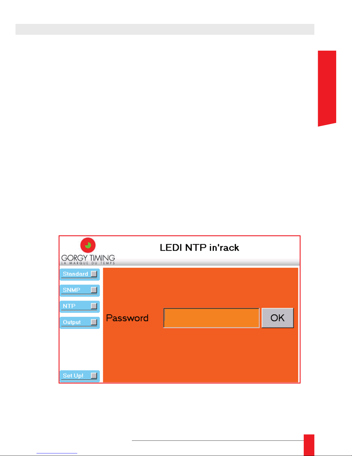
Si vous souhaitez protéger l’accès aux paramètres du LEDI Network IN, vous pouvez spécier un mot de passe. Vous devez pour cela entrer le même mot de passe dans les zones
Enter password et Conrm password.
Si vous ne voulez pas protéger les paramètres, cochez la case Without password.
Quand un mot de passe est activé, il sera demandé à la prochaine connexion. Dans ce
cas, l’écran principal a cette apparence
4. INTERFACE WEB
FRANCAIS
Page 24
24
MDE-LEDI-NETWORK-IN-4065V1.0
4.2.3. Conguration SNMP
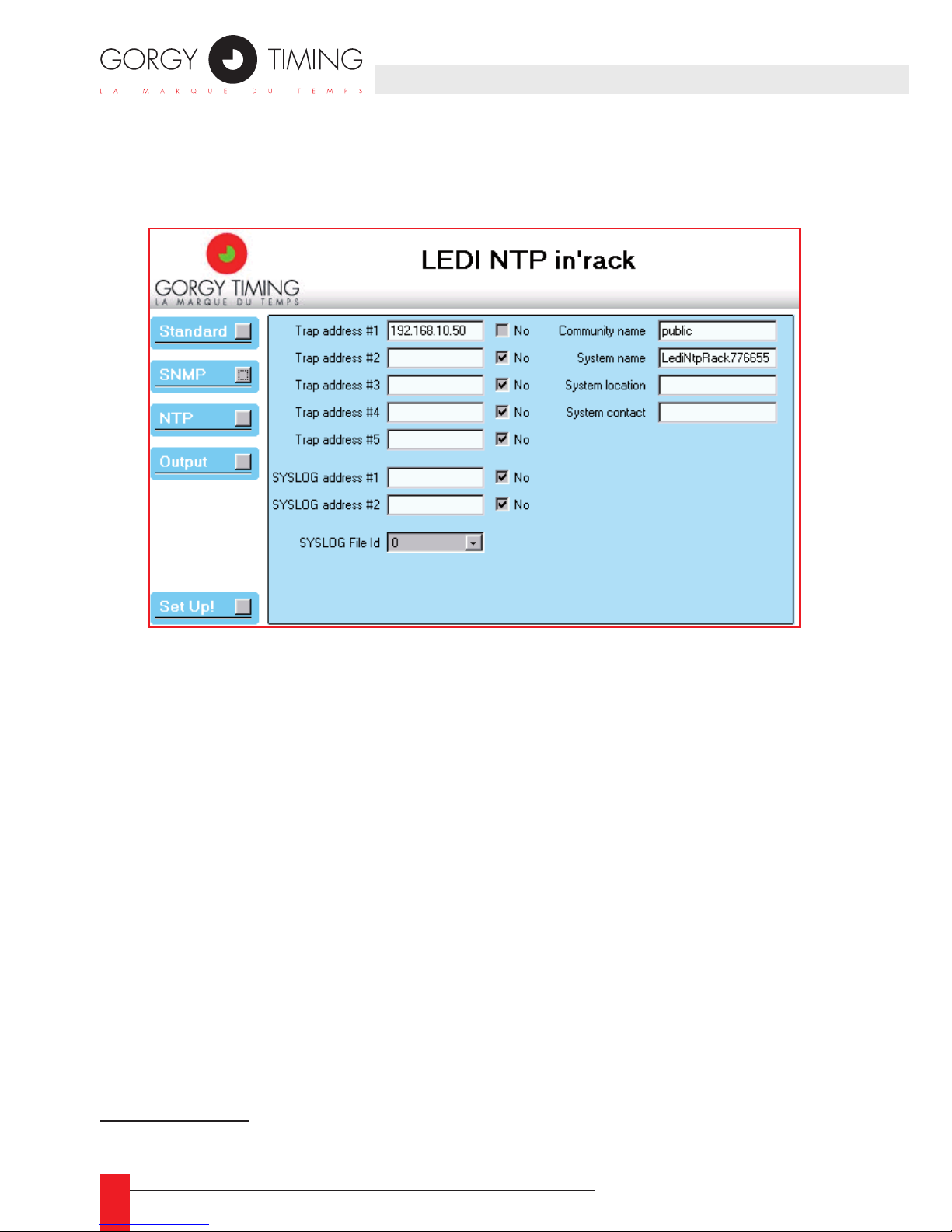
Quand vous cliquez sur le bouton SNMP, les paramètres SNMP sont afchés ainsi :
Le protocole SNMP standardisé fournit un moyen de récupérer des informations et des
alarmes du LEDI Network IN.9 L’accès à ces informations (la MIB) peut être “protégé”
par un mot clé, le Community Name.
Les alarmes sont envoyées à un navigateur SNMP localisé sur un ordinateur identié
par son adresse IP. Jusqu’à 5 adresses IP de “traps” (Trap address) peuvent-être spé-
ciées, ce qui permet de gérer les alarmes sur 5 ordinateurs différents.
Le nom du système SNMP, sa localisation, et un contact peuvent être congurés sur
cet écran. Ces informations sont enregistrées dans la branche système de la MIB et
peuvent être afchées grâce à un navigateur SNMP, ou avec l’outil GTNetMng (voir la
partie 31.2).
Par convenance, les alarmes peuvent être envoyées par le protocole SYSLOG qui est
implémenté le plus souvent sous UNIX®.
9/ Voir la partie 6 pour plus d’informations sur le SNMP
Page 25

25
MDE-LEDI-NETWORK-IN-4065V1.0
DESCRIPTION
Voici une description des champs de cet écran:
Trap address #1..#5 ►
Adresses des ordinateurs auxquels vont être envoyées les alarmes SNMP. Si vous
n’utilisez pas une adresse, cochez la case No.
SYSLOG address #1..#2 ►
Adresses des ordinateurs auxquels vont être envoyées les alarmes SYSLOG. Si
vous n’utilisez pas une adresse, cochez la case No.
SYSLOG File Id ►
dentie le chier à utiliser sur l’ordinateur distant pour le protocole SYSLOG.
Community name ►
Un simple mot clé nécessaire dans un navigateur SNMP pour accéder aux informations SNMP. Un mot clé doit avoir 8 lettres au maximum.
System name ►
Un nom que vous pouvez donner au LEDI Network IN. Ce nom apparaît dans la
variable sysName de la branche système de la MIB. La valeur initiale est LediNtpRacknnnnnn (où nnnnnn est le numéro de série du produit).
System location ►
Une éventuelle description de la localisation physique du LEDI Network IN. Ce nom
apparaît dans la variable sysLocation de la branche système de la MIB. Il n’y a
pas de valeur par défaut.
System contact ►
Personne à contacter en cas de problème avec le LEDI Network IN. Cette information apparaît dans la variable sysContact de la branche système de la MIB. Il n’y a
pas de valeur par défaut.
4. INTERFACE WEB
FRANCAIS
Page 26
26
MDE-LEDI-NETWORK-IN-4065V1.0
4.2.4. Conguration NTP
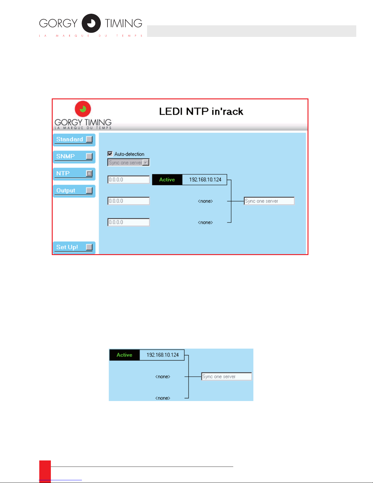
Quand vous cliquez sur le bouton NTP, la conguration de la synchronisation du LEDI
Network IN est afchée comme ci-dessous:
Le LEDI Network IN peut être synchronisé sur trois serveurs NTP au plus. En réalité,
le logiciel client NTP n’utilise qu’un seul serveur à la fois, mais peut commuter sur un
autre serveur s’il n’y a pas ou trop peu de réponses.
Le panneau de conguration NTP montre le mode de synchronisation utilisé par le
serveur ou sélectionné par le logiciel client NTP. Il montre ainsi les serveurs dénis par
l’utilisateur ou détectés par le logiciel.
DESCRIPTION
La partie droite de cet écran montre la conguration actuelle utilisée par le logiciel client NTP:
Il afche les différents serveurs utlisés pour la synchronisation et le mode actuel
de synchronisation (sur l’écran ci-dessus, il n’y a qu’un seul serveur à l’adresse IP
192.168.10.124). De plus, cet partie de l’écran montre le serveur actuellement utilisé
pour la synchronisation (avec un bandeau afchant Active). Si une commutation est en
cours, le bandeau afche Trying.
Page 27
27
MDE-LEDI-NETWORK-IN-4065V1.0
La partie gauche de l’écran NTP vous permet de congurer le mode de synchronisation
et les serveurs NTP utilisés:
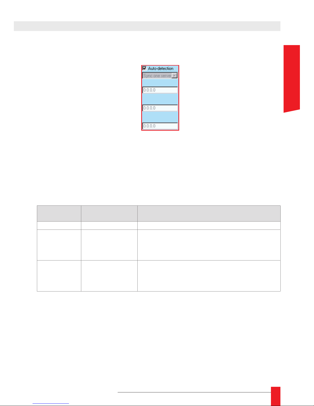
Si vous sélectionnez la case Auto-detection, le LEDI Network IN essai d’utiliser les serveurs GT NTP présents sur votre réseau et d’avoir le mode de synchronisation le plus
approprié. Si vous ne sélectionnez pas la case Auto-detection, vous devez indiquer
vous-même le mode de syncronisation et les serveurs NTP à utiliser.
La table suivante peut vous aider à choisir les paramètres les plus appropriés:
Mode
Nb de serveurs
NTP utilisés
Description
One server 1 Utilise un seul serveur pour la synchronisation
Two servers 2
Utilise le premier serveur au démarrage. Si ce ser-
veur est défaillant, commute sur le second serveur.
Si le second est défaillant, commute sur le premier,
et ainsi de suite…
Three servers 3
Utilise le premier serveur au démarrage. Si ce
serveur est défaillant, commute sur le second
serveur. Si le second est défaillant, commute sur le
troisième, et ainsi de suite…
4. INTERFACE WEB
FRANCAIS
Page 28
28
MDE-LEDI-NETWORK-IN-4065V1.0
4.2.5. Conguration des sorties
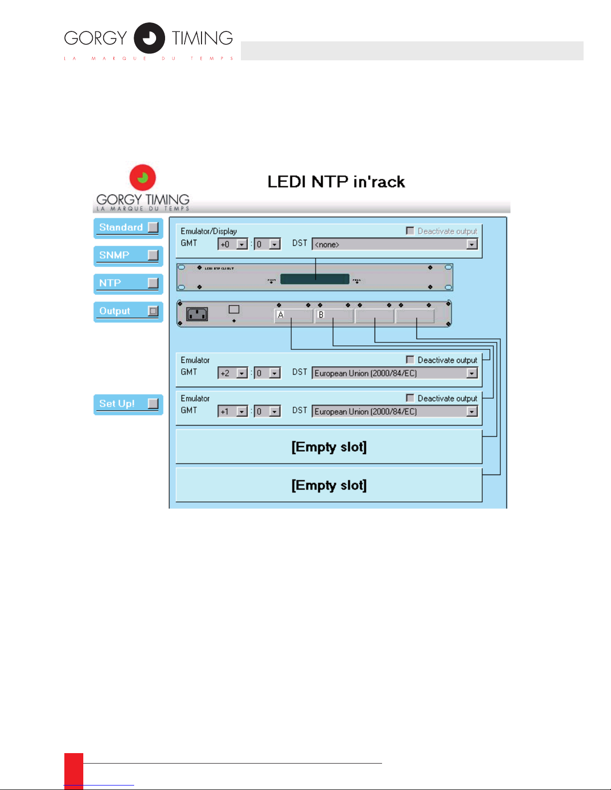
Quand vous cliquez sur le bouton Output, la conguration des sorties du LEDI Network
IN est afchée ainsi :
Ce panneau montre une vue synthétique des sorties du produit. Chaque sortie est pi-
lotée par une carte de sortie. L’afchage est considéré comme une sortie et est pilotée
par une carte d’afchage. Un LEDI Network IN peut contenir jusqu’à 4 cartes de sortie
en plus de la carte d’afchage.
Les cartes de sortie et d’afchage peuvent être contrôlées indépendamment. Dans
l’écran montré ci-dessus, chaque rectangle bleu clair sert à contrôler une carte de sor-
tie sur l’afcheur. Quand une carte de sortie est présente, elle peut-être congurée. Si
aucune carte n’est présente ou si elle est défaillante, un message est afché.
Page 29
29
MDE-LEDI-NETWORK-IN-4065V1.0
CONFIGURATION DE LA SORTIE STANDARD
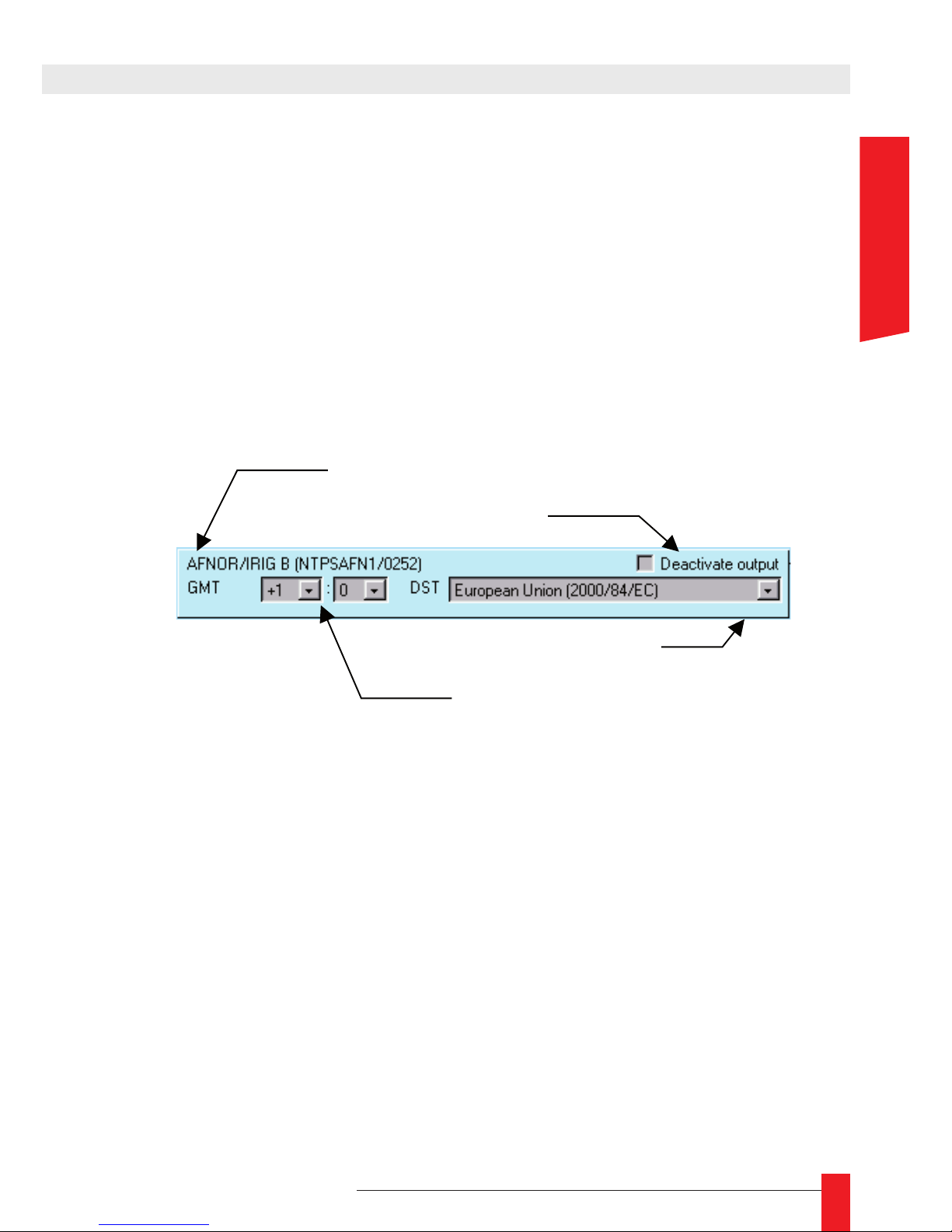
Chaque carte de sortie peut-être congurée grâce aux paramètres suivant:
Vous pouvez désactiver la carte de sortie. Quand une carte est désactivée, le code ►
horaire n’est plus généré en sortie. Pour désactiver la sortie, cochez la case Deac-
tivate output.
Vous pouvez spécier un fuseau horaire (un décalage) à appliquer sur la sortie de ►
la carte par rapport à l’heure UTC.
Vous pouvez spécier une politque de changement d’heure (DST) à appliquer sur ►
la sortie de la carte par rapport à l’heure UTC.
L’image ci-dessus montre le panneau de conguration pour une carte AFNOR/IRIG-B. De
plus, la description contient l’identication et la version du programme incorporé dans la
carte de sortie (ici, c’est le programme NTPSAFN1, version 0252).
Décalage par rapport à
l’heure UTC (fuseau horaire)
4. INTERFACE WEB
FRANCAIS
Page 30
30
MDE-LEDI-NETWORK-IN-4065V1.0
5.1. PRÉSENTATION
Le LEDI Network IN fournit une interface SNMP v1 pour la surveillance et le diagnostique.
Le protocole SNMP permet la supervision d’un appareil par le réseau. Deux types d’informations sont disponibles par l’interface SNMP :
Des variables peuvent être lue depuis un superviseur SNMP. Ces variables sont ►
stockées ensemble dans une base de données (MIB) organisée de manière hiérarchique. Les variables sont renseignées par le logiciel NTP pour reéter son état
interne.
Certains “traps” peuvent être générés par le logiciel NTP pour indiquer une impor- ►
tante modication d’état.
Il y a deux parties importantes dans la MIB:
Une branche générale appelée ► System. Cette branche est compatible MIB II.
Une branche privée qui contient des informations spéciques au produit LEDI ►
Network IN.
Les MIBs privées sont décrites avec des chiers .MIB. Deux chiers .MIB sont fournit sur
le CD-ROM dans le répertoire English\LEDINETWORKIN\MIB:
Le chier ► GtNtpOutBus.mib contient la description des informations concernant la
localisation des cartes de sortie dans la MIB:
iso(1).org(3).dod(6).internet(1).private(4).enterprises(1).gorgy(8955).hardware(2).ntpOutBus(1)
Le chier ► GtNtpClient.mib contient la description des informations concernant la
localisation du logiciel client NTP dans la MIB:
iso(1).org(3).dod(6).internet(1).private(4).enterprises(1).gorgy(8955).software(1).ntpClient(4)
Page 31
31
MDE-LEDI-NETWORK-IN-4065V1.0
5. INTERFACE SNMP
5.1.1. Structure de la MIB privée pour le LEDI Network IN
SOFTWARE
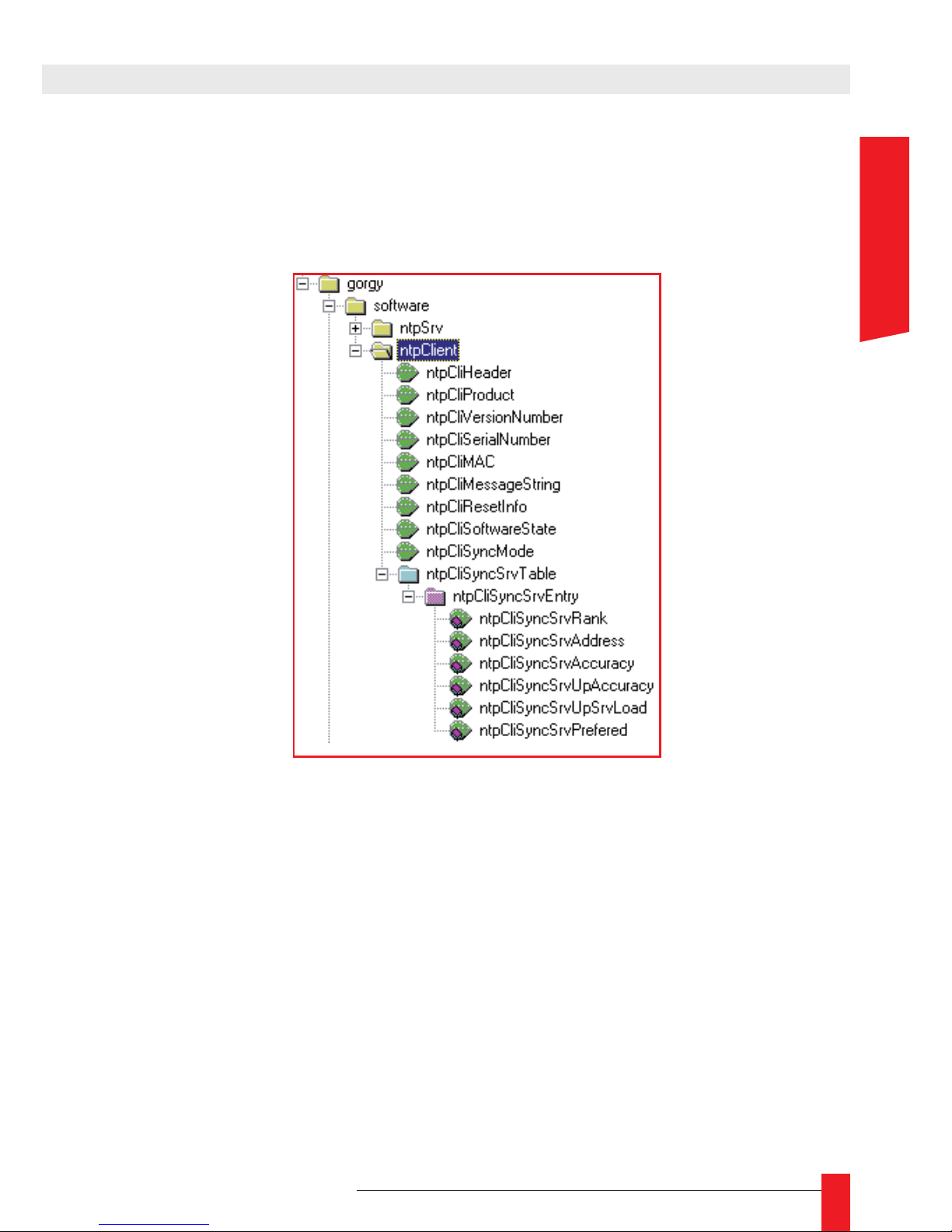
Cette branche contient toutes les informations concernant le logiciel client lui-même.
Voici la structure de la branche:
Les différents champs de cette branche sont décrit ci-dessous:
ntpCliHeader ►
Une courte description du produit. Il est du type GT LEDI Network IN client nnnnnn
Vxx.yy (aammjj) où xx.yy est la version courante du logiciel, aammjj est la date
d’émission du logiciel (jj/mm/aa) et nnnnnn est le numéro de série du produit.
ntpCliProduct ►
Une description du produit avec ses options qui doit être similaire au code produit
(décrit dans Annexe D – Guide des codes produits). Par exemple 9257/ AB........
D indique un LEDI Network IN avec des sorties IRIG-B et ASCII et un afcheur
(code D).
ntpCliVersionNumber ►
Version de ce produit. Il est du type Vxx.yy (aammjj) où xx.yy est la version actuelle
du logiciel, aammjj est la date d’émission du logiciel (jj/mm/aa)
FRANCAIS
Page 32
32
MDE-LEDI-NETWORK-IN-4065V1.0
ntpCliSerialNumber ►
Numéro de série sur 6 chiffres.
ntpCliMAC ►
Adresse matérielle de l’interface Ethernet du LEDI Network IN. Cette adresse est de
la forme aa:bb:cc:dd:ee (6 octets binaires).
ntpCliMessageString ►
Description du dernier “trap” généré. Ce texte est lié au trap.
ntpCliResetInfo ►
Indication sur la raison du dernier redémarrage (reconguration ou RAZ manuelle).
ntpCliSoftwareState ►
Ce champ donne l’état actuel du logiciel client NTP. Il peut prendre l’une de ces
valeurs:
Idle ► : Le produit vient de démarrer.
Autodetection ► : aucun serveur NTP n’a été spécié et le produit essaye de
détecter des serveurs NTP.
Autodetectfail ► : aucun serveur NTP trouvé pour la synchronisation – le produit
utilisera un serveur dès que vous en connecterez un sur le réseau.
Learning ► : le logiciel étudie actuellement les propriétés réseau.
ntpCliSyncMode ►
Le mode de synchronisation actif actuellement. Il peut prendre les valeurs suivantes :
Autodetect ► : aucun serveur NTP n’a été spécié et le produit essaye de détecter
des serveurs NTP.
Sync1server ► : travaille avec un seul serveur NTP.
Sync2server ► : travaille avec deux serveurs NTP. Quand un serveur est dé-
faillant, il utilise l’autre.
Sync3server ► : travaille avec trois serveurs NTP. Quand un serveur est défaillant,
il utilise un des autres serveur.
ntpCliSyncSrvTable ►
Ce tableau contient tous les serveurs utilisés pour la synchronisation et d’autres informations. Lma première entrée de la table est le serveur actuellement utilisé pour
la synchronisation. La seconde entrée est le second serveur préféré, etc. Chaque
entrée est de ce type :
ntpCliSyncSrvRank ► :
Rang du serveur. Un serveur de rang est est utilisé pour la synchronisation.
ntpCliSyncSrvAddress ► :
Adresse IP du serveur.
ntpCliSyncSrvAccuracy ► :
Précision du serveur comme fournit dans la trame NTP (du type 2^-x secon
des).
Page 33
33
MDE-LEDI-NETWORK-IN-4065V1.0
ntpCliSyncSrvUpAccuracy ► (Serveur Gorgy Timing seulement)
Précision du serveur fournit durant l’étape d’auto-détection.
ntpCliSyncSrvUpSrvLoad ► (Serveur Gorgy Timing seulement)
Charge du serveur (nombre moyen de requêtes par secondes) fournit durant
l’étape d’auto-détection.
ntpCliSyncSrvPrefered ► (Serveur Gorgy Timing seulement)
Un numéro dénit par l’utilisateur qui indique le rang de ce serveur. Quand
l’auto-détection est activée, le LEDI Network IN utilise le serveur de plus haut
rang.10
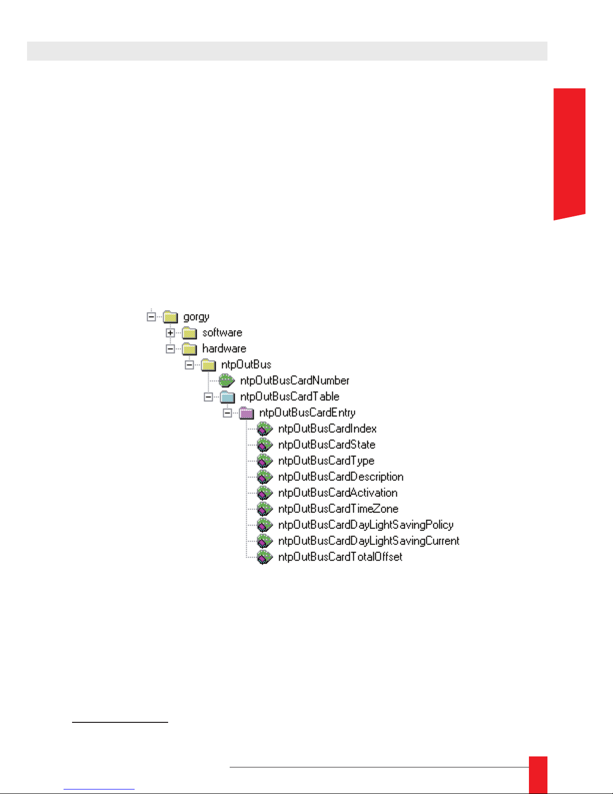
HARDWARE
La MIB décrit les cartes détectées et leurs congurations. Toutes les cartes de sortie et
l’afcheur sont connectés au même bus de sortie.
Voici la description des différents champs de cette branche:
ntpOutBusCardNumber ►
Nombre de cartes détectées sur le bus de sortie.
ntpOutBusCardTable ►
Une table qui montre toutes les cartes détéctées sur le bus de sortie. Chaque
carte est indéxéepar son adresse (1…9 pour les cartes de sortie et 9 pour l’afcheur). Chaque entrée est de ce type.
10/ Voir la documentation du serveur NTP que vous utilisez pour congurer la préférence
5. INTERFACE SNMP
FRANCAIS
Page 34
34
MDE-LEDI-NETWORK-IN-4065V1.0
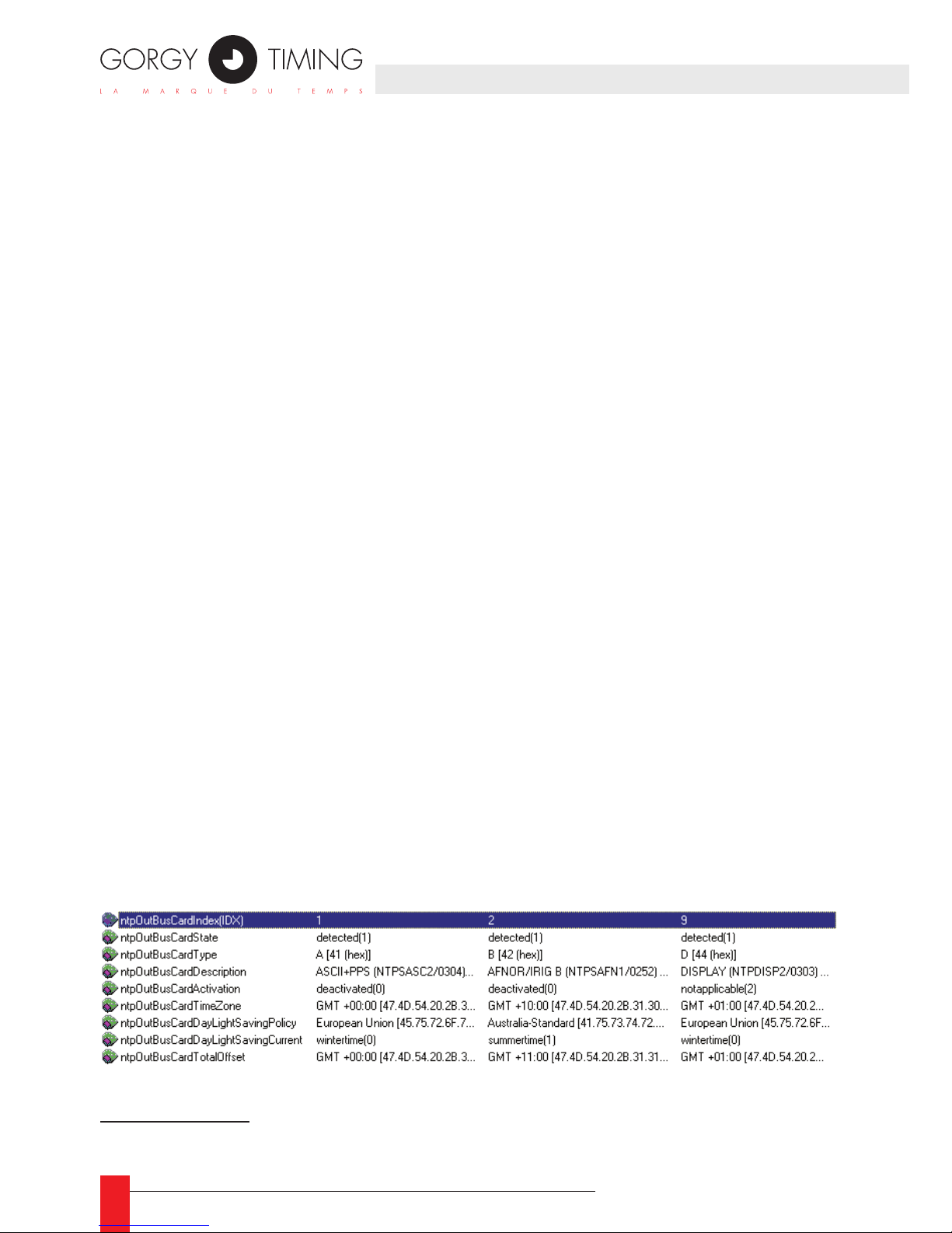
ntpOutBusCardIndex ► :
Index de cette entrée (adresse de la carte). Cette valeur peut prendre la valeur 1 à
8 pour une carte de sortie et 9 pour l’afcheur.
ntpOutBusCardState ► :
L’état de la carte. Il peut être detected pour indiquer que la carte fonctionne
correctement, failure si la carte ne répond pas ou scrambled si la réponse de la
carte est incorrecte.
ntpOutBusCardType ► :
Type de carte (voir Annexe D – Guide des codes produits pour la liste des types
de cartes de sortie possible).
ntpOutBusCardDescription ► :
Description de la carte.
ntpOutBusCardActivation ► :
Indique si la sortie de la carte est activée (activated) ou désactivée (deactivated) : l’activation de la carte peut être controllée par l’interface WEB.
Si la carte ne peut être désactivée, ce champs prend la valeur notapplicable.
11
ntpOutBusCardTimeZone ► :
Fuseau horaire pour cette sortie. Il est donné comme un offset par rapport au
temps universel. Il peut-être changé par l’interface WEB.
ntpOutBusCardDayLightSavingPolicy ► :
Indique quelle politique de changement d’heure (DST) est utilisée. S’il n’y a pas
de DST, ce champs a la valeur <none>. Cette politique peut être changée via
l’interface WEB.
ntpOutBusCardDayLighSavingCurrent ► :
Indique si la politique de changement d”heure (DST) est en fonctionnement
(valeur summertime) ou pas (valeur wintertime). Si le DST n’est pas activé, ce
champs, ce chanmps a la valeur notapplicable.
ntpOutBusCardTotalOffset ► :
Indique le décalage total actuel par rapport à l’heure universelle UTC.
Voici un exemple de la description de la carte de sortie afchée dans un navigateur
SNMP:
11/ L’afcheur ne peut être désactivé par exemple
Page 35
35
MDE-LEDI-NETWORK-IN-4065V1.0
Cette annexe contient une description des différents connecteurs du LEDI Network
IN. Toutes les prises sont localisées à l’arrière du produit. Actuellement, seuls deux
types de sorties sont disponibles.
1. CONNEXION POUR TOUS LES PRODUITS
1.1. Produits 230V et 115V AC (type ‘0’)
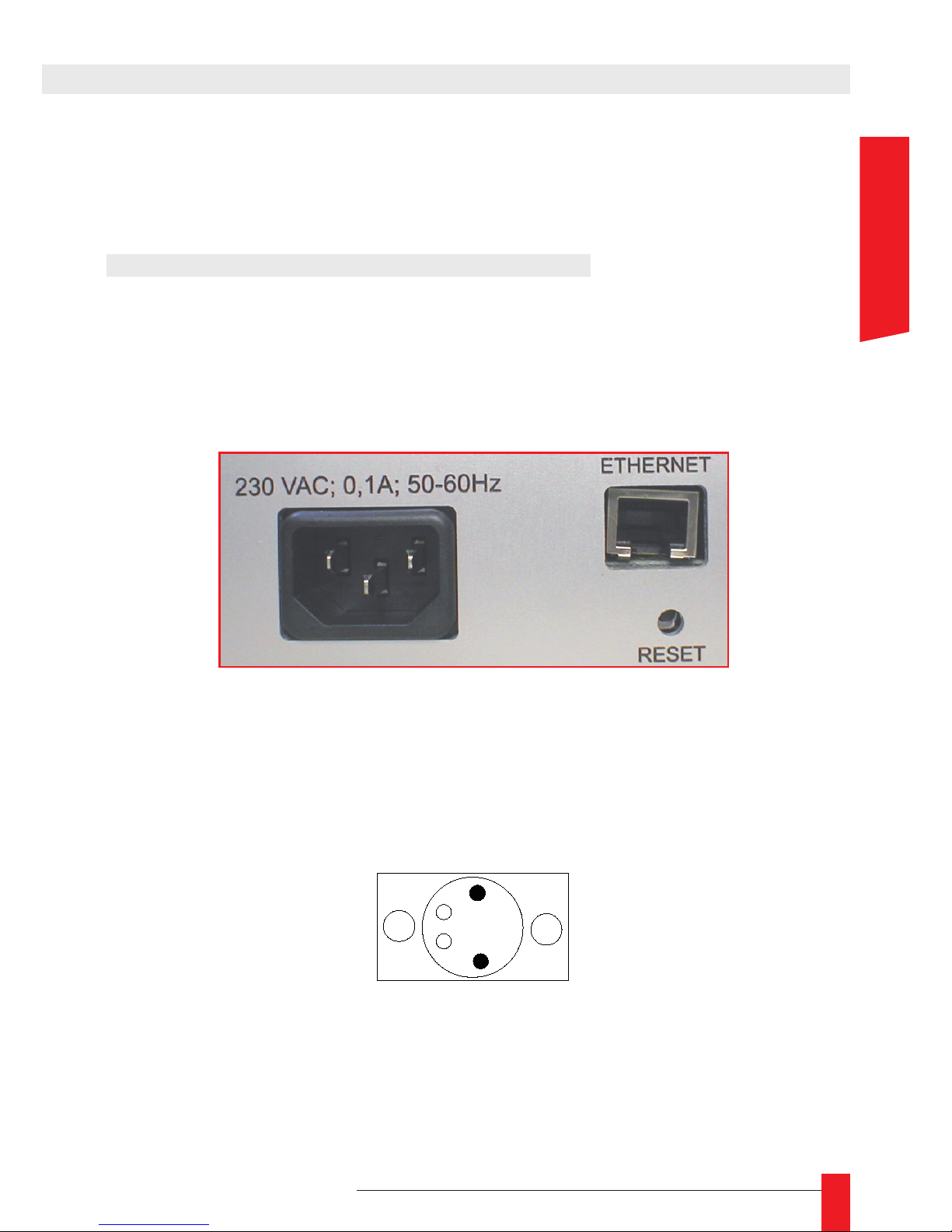
L’arrière du produit possède une prise d’alimentation standard, une prise Ethernet RJ45
et un bouton RESET comme ci-dessous:
1.2. 18/72V DC product (type ‘9’)
Le connecteur Ethernet et le bouton RESET sont identiques.
Seul le connecteur d’alimentation diffère.
6
ANNEXE A – CONNEXIONS
0V
+V DC
FRANCAIS
Page 36
36
MDE-LEDI-NETWORK-IN-4065V1.0
2. SORTIE POUR CARTE TYPE ‘B’
(SORTIE DOUBLE AFNOR/IRIG-B NFS87500)
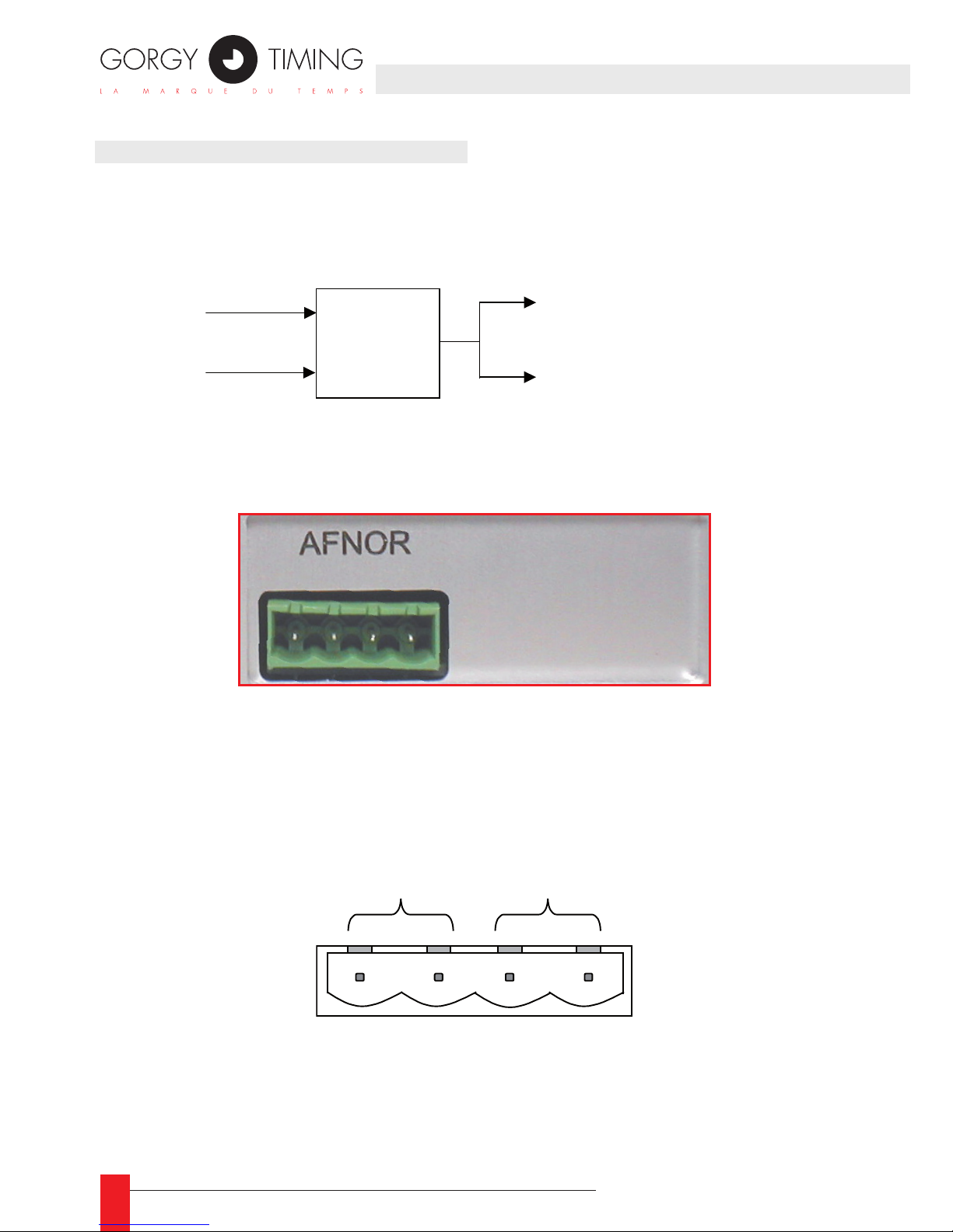
Cette carte a sa sortie sur une simple prise 4 points. Le code AFNOR est disponible en
double sur cette sortie. Voici une vue schématique de la carte de sortie AFNOR/IRIG-B:
Le connecteur de sortie est localisé sur la face arrière du rack comme ci-dessous:
Voici les pattes du connecteur (le même signal est généré sur les sorties ½ et ¾):
Code horaire
Modulateur
d’amplitude
Sortie 2
Sortie 1
1 2 3 4
Page 37
37
MDE-LEDI-NETWORK-IN-4065V1.0
3. SORTIE POUR CARTE TYPE ‘A’ (ASCII+TOP)
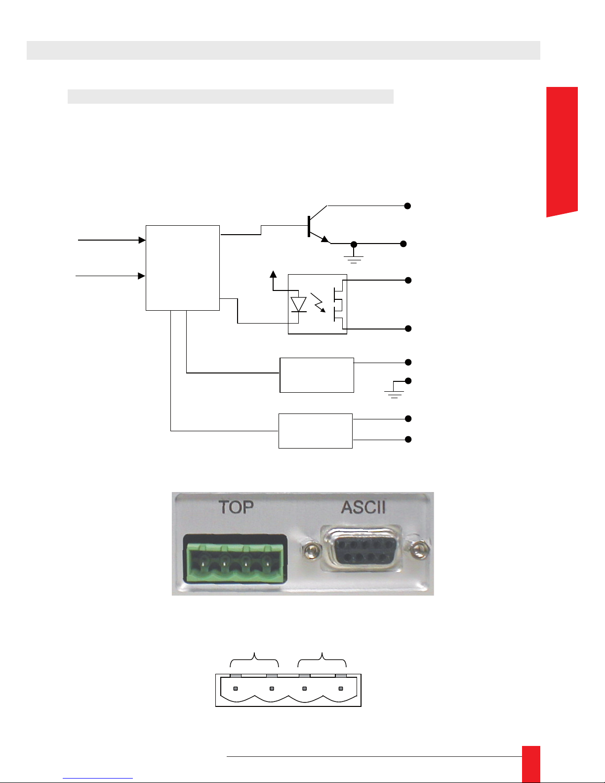
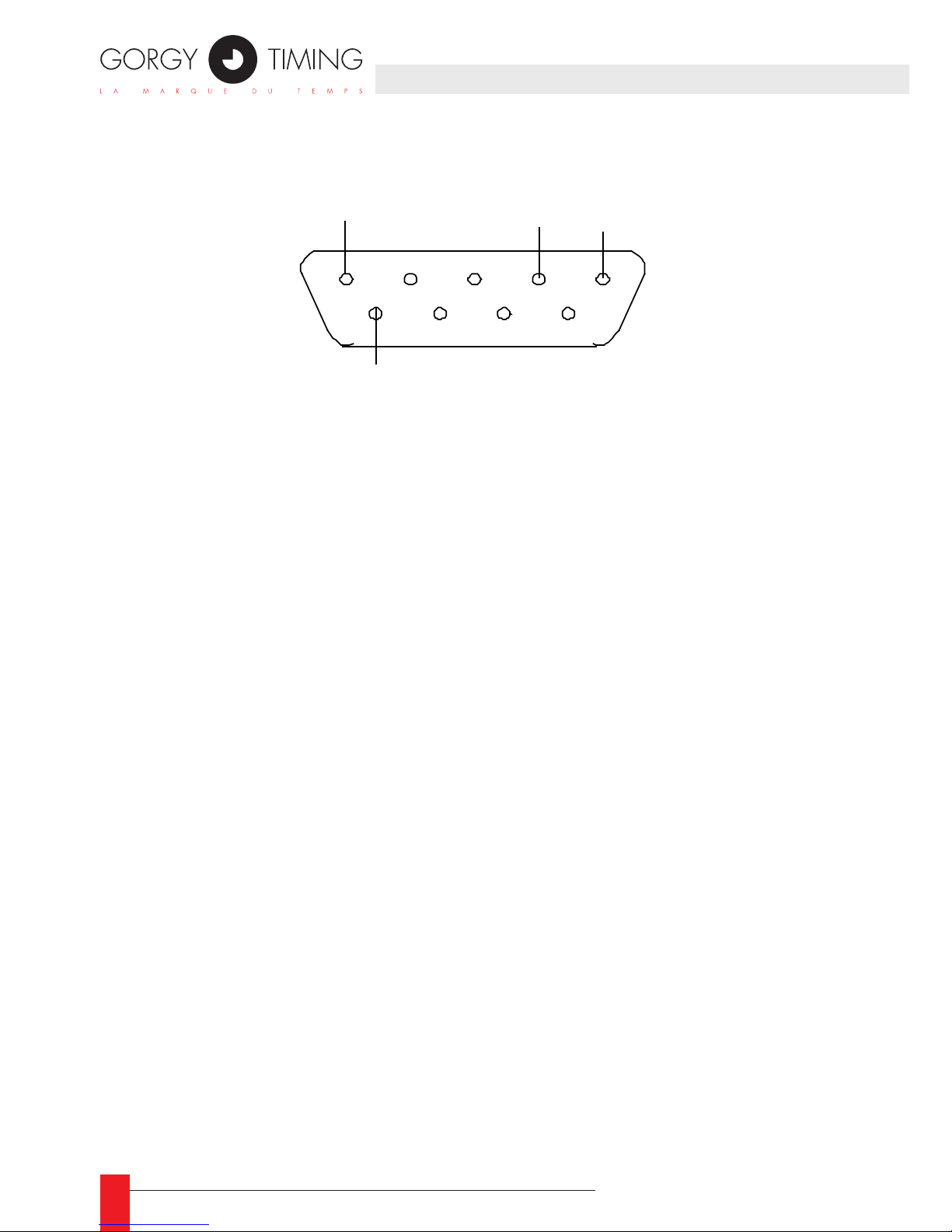
Cette carte possède une prise 4 points et un connecteur DB9 La prise 4 points sort le TOP
de deux manières différentes et la prise DB9 fournit la trame horaire en sortie en niveau
RS-232 ou RS-485.
Voici une vue schématique de la sortie ASCII+TOP:
Les connecteurs de sortie sont sur la face arrière du rack comme ci-dessous:
La prise 4 points a le format suivant :
Driver
Sortie collecteur ouvert
Sortie relais statique
Driver de
ligne RS-232
Driver de
ligne RS-485
TXD
TX+
TX-
Sortie RS-232
Sortie RS-485
Sortie collecteur ouvert
Sortie relais statique
1 2 3 4
6
ANNEXE A – CONNEXIONS
FRANCAIS
Page 38
38
MDE-LEDI-NETWORK-IN-4065V1.0
Le connecteur DB9 a le format suivant:
5 4 3 2 1
9 8 7 6
GND
TXD
TX+
TX-
Page 39
39
MDE-LEDI-NETWORK-IN-4065V1.0
Cette annexe contient une description du code horaire utilisé pour les différentes
sorties.
1. CARTE TYPE ‘A’ (SORTIE ASCII+TOP)
Voici la conguration par défaut :
La pulsation PPS est générée toutes les 30 secondes et dure 1 seconde. ►
La trame ASCII est générée au même moment que le PPS. Cette trame contient 23 ►
caractères avec le format suivant :
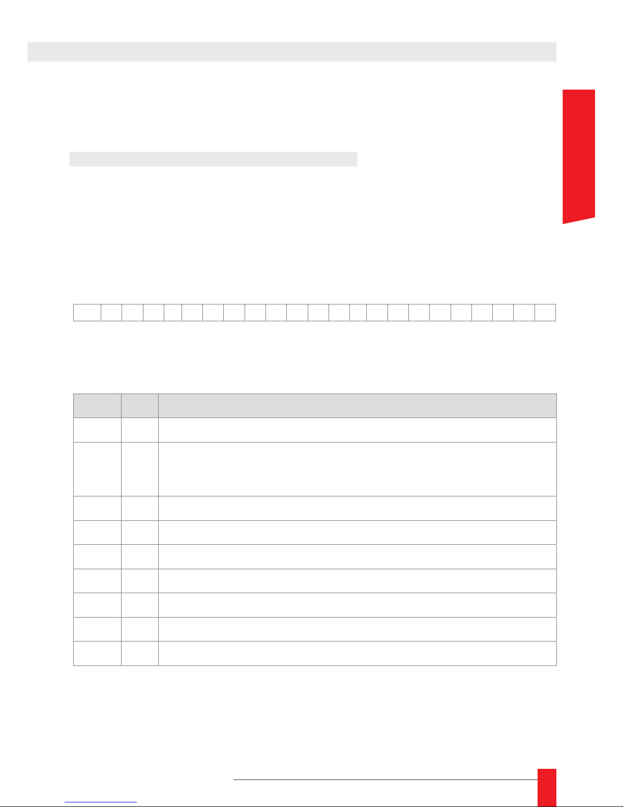
STX D A Y D D / M M / Y Y H H : M M : S S CR
Voici une description des différents champs de la trame :
Field Size Value/Meaning
STX 1 Un simple octet de valeur 2, qui signale le début de la trame.
DAY 3
Le jour de la semaine en anglais (MON pour Lundi, TUE pour Mardi,
WED pour Mercredi, THU pour Jeudi, FRI pour Vendredi, SAT pour
samedi, SUN pour Dimanche)
DD 2 Jour du mois en 2 caractères ASCII (01-31)
MM 2 Mois dans l’année en 2 caractères ASCII (01-12)
YY 2 Année en 2 caractères ASCII (00 for 2000 – 99 for 2099)
HH 2 Heure en 2 caractères ASCII (00 to 23)
MM 2 Minutes en 2 caractères ASCII (00 to 59)
SS 2 Secondes en 2 caractères ASCII (00 to 59)
CR 1 Un simple octet de valeur décimale 13, qui signale la n de la trame
ANNEXE B – FORMAT DU CODE DE SORTIE
FRANCAIS
Page 40
40
MDE-LEDI-NETWORK-IN-4065V1.0
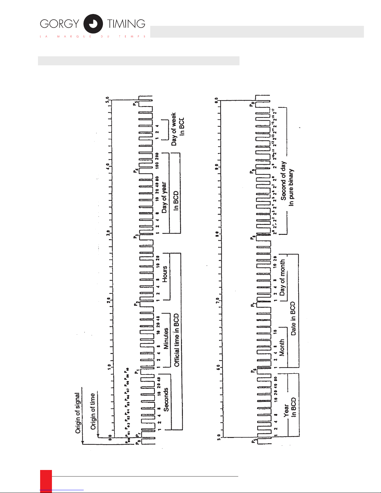
2. CARTE TYPE ‘B’ (AFNOR/IRIG-B NFS87500)
2.1. Format de la trame
Page 41
41
MDE-LEDI-NETWORK-IN-4065V1.0
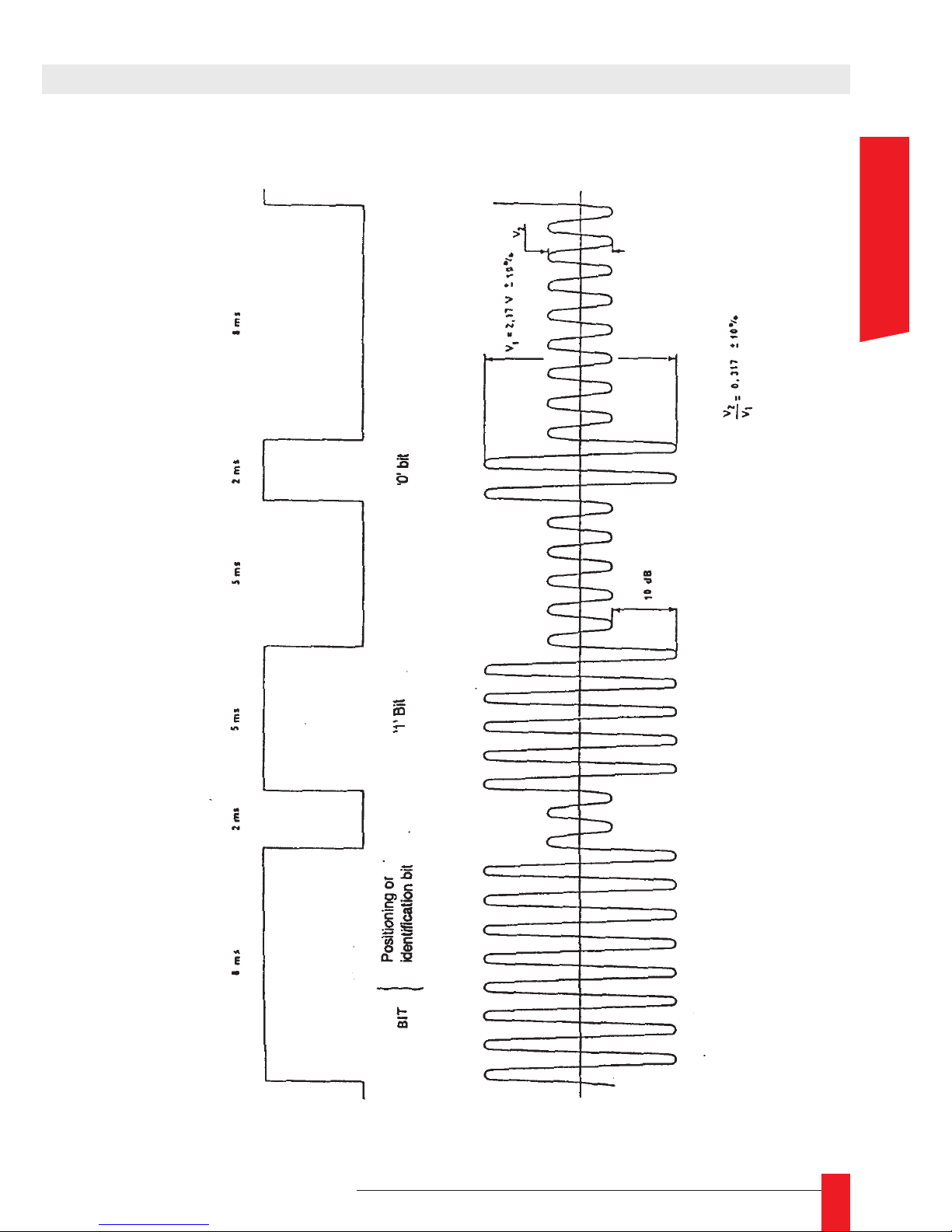
ANNEXE B – FORMAT DU CODE DE SORTIE
2.2. Encodage des bits
FRANCAIS
Page 42
42
MDE-LEDI-NETWORK-IN-4065V1.0
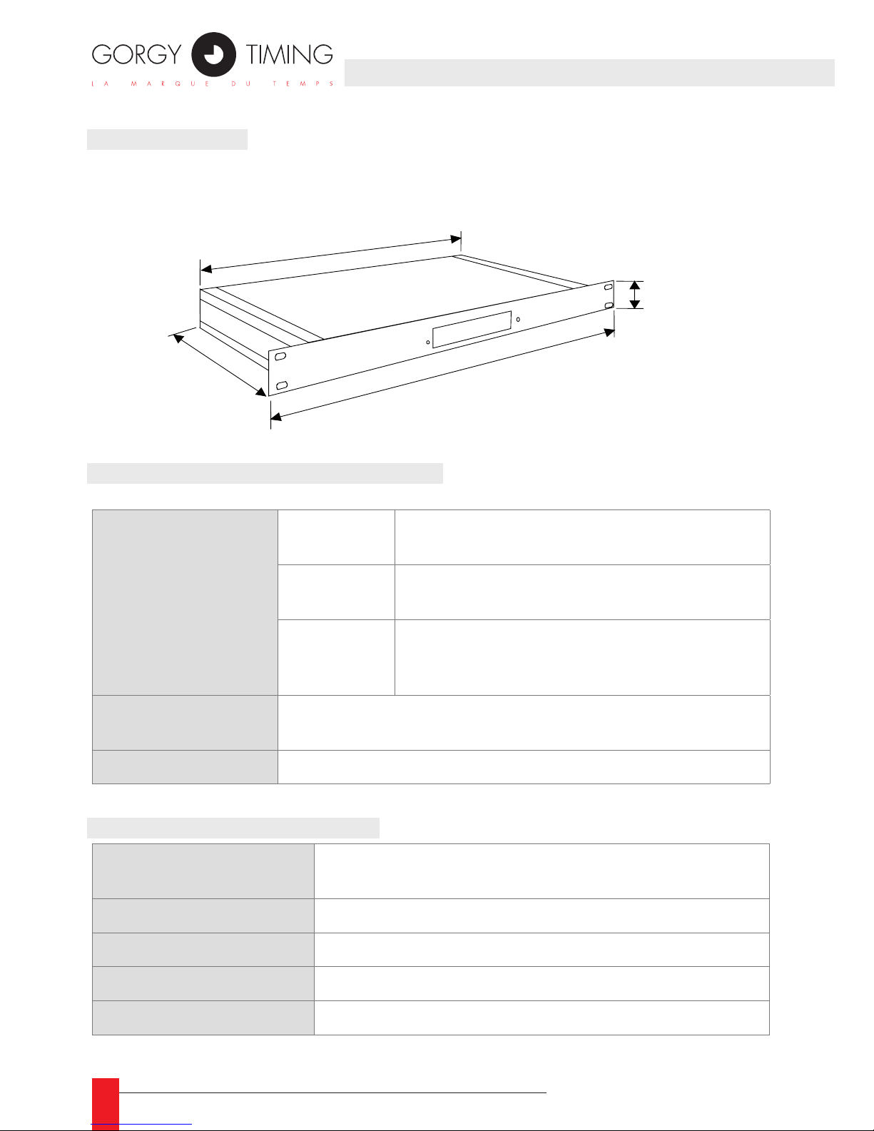
1. DIMENSIONS
Le rack est au format standard 19” 1U rack. Voici ses dimensions:
2. SPÉCIFICATIONS ÉLECTRIQUES
Consommation
électrique
230 V AC
Maximum: 0,1 A max.
Typique : 20 mA plus 2mA par sortie
115V AC
Maximum : 0,2 A max.
Typique : 40 mA plus 4mA par sortie
18-72V DC
Maximum : 0,6-0,15 A max.
Typique : 250mA plus 25 mA par sortie (18V)
62mA plus 7 mA par sortie (72V)
Environnement
Température de fonctionnement : 5 à 50°C (41 à 122°F)
Température de stockage : -40 à 70°C (-40 à 151°F)
Autonomie électrique 4 heures sur les batteries internes
3. AUTRES SPÉCIFICATIONS
Protocoles supportés
ARP,UDP,TCP,Telnet,ICMP,SNMP,DHCP,TFTP,
HTTP,ENDMI, AutoIP, JAVA, SNTP client
Interface réseau 10Base-T avec interface RJ-45
Management SNMP, serveur WEB, Telnet, ENDMI
Mise à jour Possible par le serveur TFTP
Mémoire ROM:512K, RAM:128K, EEPROM:2K
1U = 44 mm
424 mm
263 mm
482 mm
Page 43

43
MDE-LEDI-NETWORK-IN-4065V1.0
ANNEXE D – GUIDE DES CODES PRODUITS
1. LOCALISATION DE L’ÉTIQUETTE
L’étiquette qui identie le produit se situe sur le dessus ou la face arrière du produit.
2. INFORMATIONS DE L’ÉTIQUETTE
L’étiquette contient les informations suivantes:
GORGY TIMING
CODE 9257/Xopt
N° SERIE nnnnnn
La troisième ligne contient le numéro de série sur 6 chiffres (nnnnnn).
La seconde ligne est la description du produit:
9257/ X opt
Une ou plusieurs lettres (une lettre par sortie):
A ASCII+TOP
B IRIG-B/AFNOR NFS87500
Une lettre qui indique le type d’alimentation:
9 Pour courant continu 18 à 72V
0 Pour courant alternatif 230V 50Hz
Identication du produit LEDI Network IN
Par exemple, le code 9257/9AB identie un LEDI Network IN avec une alimentation courant continu 18/72V et deux sorties. La première sortie utilise le protocole ASCII, la secon-
deest une sortie IRIG-B/AFNOR.
FRANCAIS
Page 44
44
MDE-LEDI-NETWORK-IN-4065V1.0
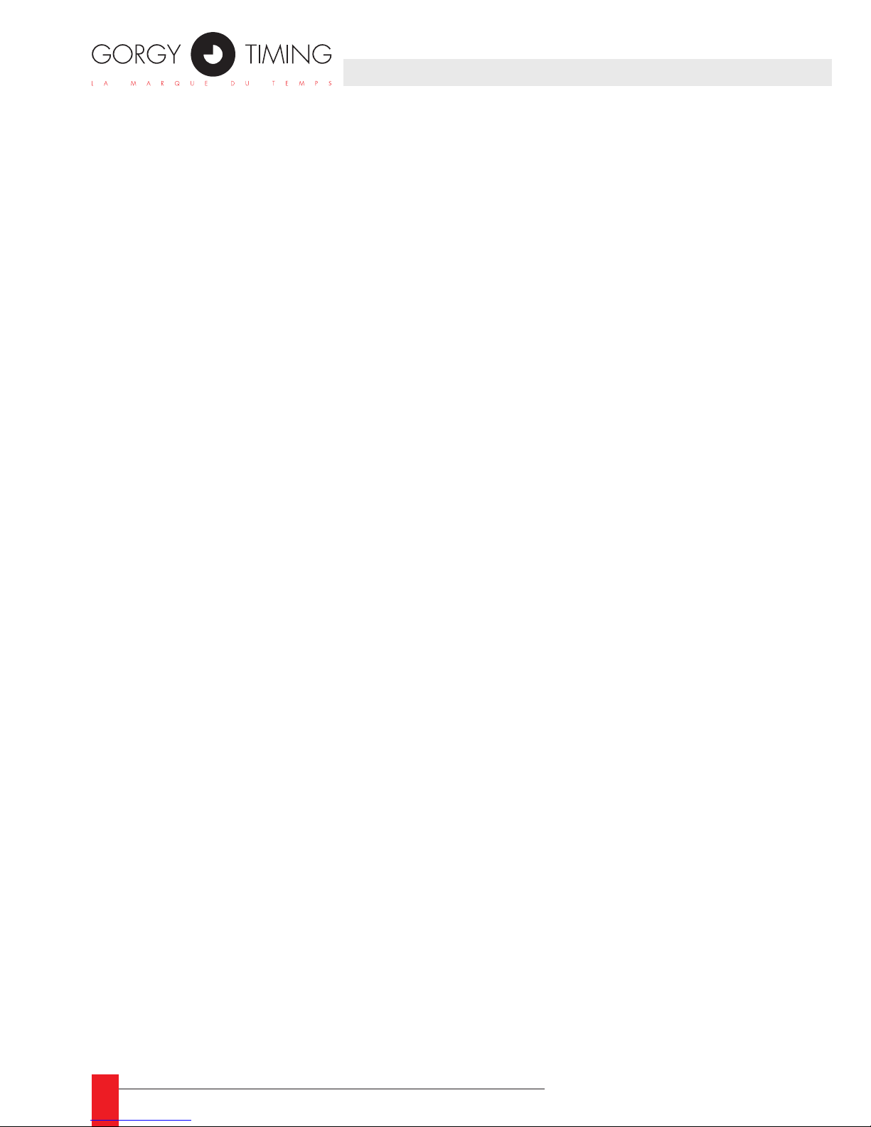
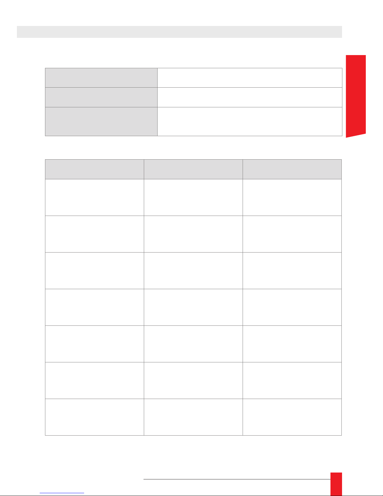
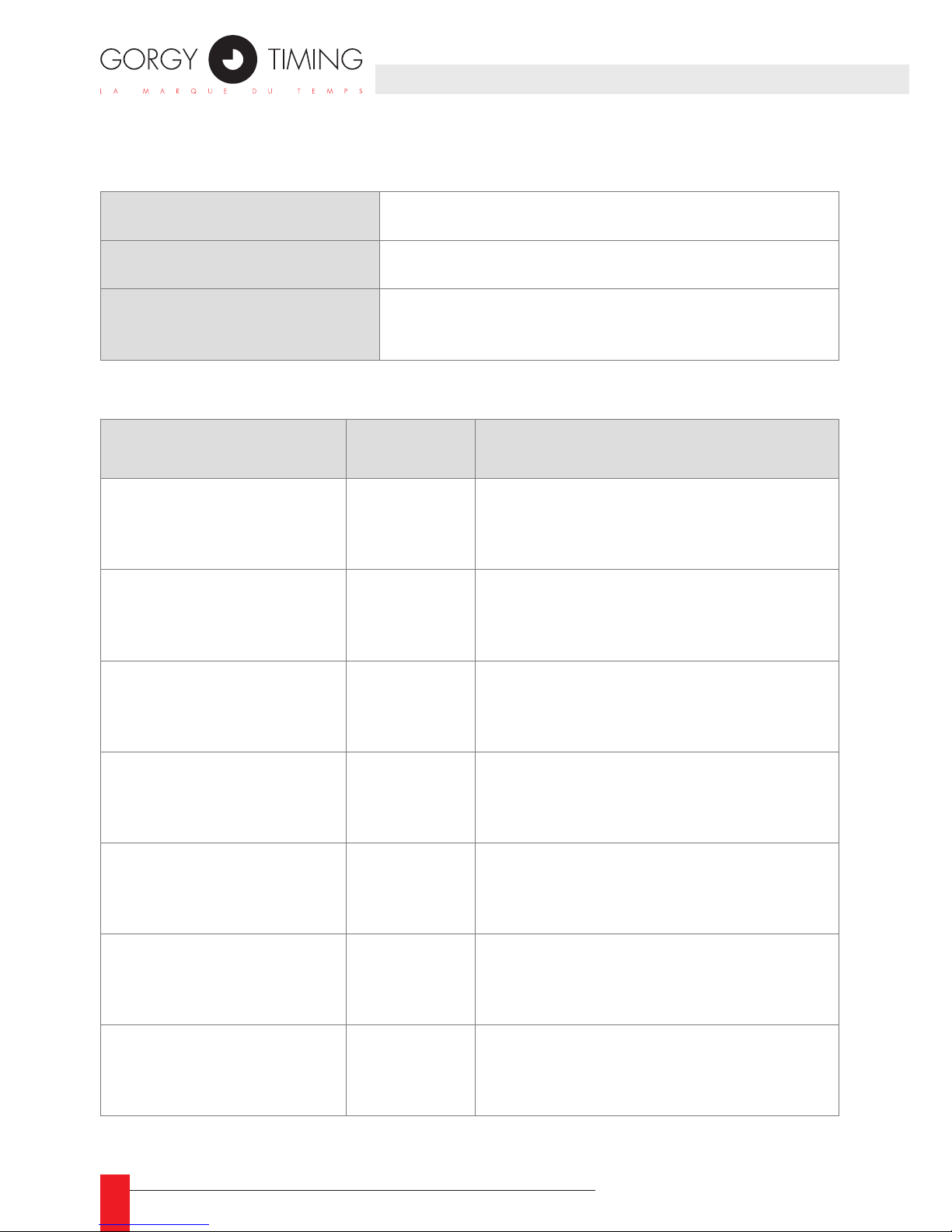
Cette annexe contient quelques documents utiles pour gérer un ensemble de produits GT dans vote installation. Chaque document est une table que vous pouvez
librement copier et distribuer:
Description de l’installation: vous pouvez utiliser cette table pour créer une vue ►
synthétique de toute votre installation.
Conguration de l’appareil : vous pouvez utiliser cette table pour enregistrer la ►
conguration des sorties et afcheur de chaque produit.
ANNEXE E – DOCUMENTS COMPLÉMENTAIRES
Page 45
45
MDE-LEDI-NETWORK-IN-4065V1.0
ANNEXE E – DOCUMENTS COMPLÉMENTAIRES
Vue résumée de l’installation
Description de l’installation
Date d’installation
Nom de l’installateur
Description du produit Numéro de série Localisation
FRANCAIS
Page 46
46
MDE-LEDI-NETWORK-IN-4065V1.0
Conguration des appareils
Description de l’installation
Date d’installation
Nom de l’installateur
Appareil Sortie
Fuseau horaire et politique
de changement d’heure
ANNEXE E – DOCUMENTS COMPLÉMENTAIRES
Page 47
47
MDE-LEDI-NETWORK-IN-4065V1.0
NOTES
FRANCAIS
Page 48
48
MDE-LEDI-NETWORK-IN-4065V1.0
5. OPTION CHRONOMÈTRE
RADIO TIMING®, LEDI ®, LEDI CA®, HANDI ® sont des marques déposées GORGY TIMING.
Numéro de déclaration d’activité de prestataire de formation : 82 38 04877 38
GORGY TIMING RC 74 B 38 - Toutes modications d'ordre technique ou esthétique peuvent être apportées sans préavis.
SUPPORT TECHNIQUE
DEPUIS LA FRANCE SUR UN POSTE FIXE :
GORGY TIMING SAS
Quartier Beauregard
38350 La Mure d'Isère (Grenoble France)
Phone: +33 4 76 30 48 20 Fax: +33 4 76 30 85 33
email: [email protected] - www.gorgy-timing.com
Page 49

49
MDE-LEDI-NETWORK-IN-4065V1.0
USER GUIDE
LEDI® NETWORK IN
ENGLISH
Page 50
50
MDE-LEDI-NETWORK-IN-4065V1.0
WARNING! Read the section that follows very carefully before installing your equipment. It gives the safety instructions to follow during installation.
The electrical installation to which the equipment is connected must comply with
the NF C 15-100 standard.
This device does not have a primary power switch. A power protection system
(circuit-breaker or disconnecting switch), that is easy to access must be built into
the wiring installation. This device must support the nominal voltage and current
values specied on the clock.
In Europe: to comply with European regulations on the protection of persons and
the environment, you must dispose of this equipment in a collection site provided
for this purpose (separately from household waste). Contact your reseller, collection site or the competent lcoal authorities for more information.
Toute modication ou ouverture du produit sans l’accord du SAV entraîne la perte
de la garantie.
All maintenance operation shall be conducted with power shut off, including systems connected on relay outputs if any.
Generally, the power cable (220V) and transmission cable (of time signal) shall
not be very close to each other, so as to avoid interference (keep the distance of
a few centimeters).
Gorgy Timing disclaims all responsibility in case of accident or damage caused by
an improper use of the product.
GORGY TIMING products are compliant with the following standards: CE, EN 60950,
EN 55022, EN 50024
IMPORTANT SAFETY INSTRUCTIONS
Page 51

51
MDE-LEDI-NETWORK-IN-4065V1.0
CONTENTS
1. INTRODUCTION .......................................................................................................... 53
1.1. Quick installation ................................................................................................................ 53
1.1.1. Check the package content .................................................................................... 53
1.1.2. Connect the product ............................................................................................... 54
1.2. Set-up your product ............................................................................................................ 54
2.1.1. Manual network conguration ................................................................................. 54
2.1.2. Output cards conguration ..................................................................................... 55
1.3. Basics ................................................................................................................................. 55
1.3.1. Synchronization concepts ....................................................................................... 55
A/ Clock Correction principles ..................................................................................... 55
B/ Network dialog ........................................................................................................ 57
C/ Working with several servers.................................................................................. 57
1.3.2. The NTP client software ......................................................................................... 58
2. FULL SETUP ............................................................................................................... 59
2.1. Network conguration ......................................................................................................... 59
2.1.1. Default conguration ............................................................................................... 59
2.1.2. Changing network parameters ............................................................................... 59
2.1.3. Integration in your network ..................................................................................... 61
2.2. Output cards conguration ................................................................................................ 62
2.2.1. Introduction ............................................................................................................. 62
2.2.2. Default conguration ............................................................................................... 62
2.2.3. Change the settings ................................................................................................ 62
3. FRONT DISPLAY INTERFACE .................................................................................... 64
3.1. Start-up conditions .............................................................................................................. 64
3.2. Time display ........................................................................................................................ 65
3.3. Alarm condition ................................................................................................................... 66
4. WEB INTERFACE ........................................................................................................ 67
4.1. Presentation ....................................................................................................................... 67
4.2. Description of the WEB interface ........................................................................................ 68
4.2.1. Ecran Principal ....................................................................................................... 68
4.2.2. Standard setup ....................................................................................................... 69
4.2.3. SNMP setup ........................................................................................................... 72
4.2.4. NTP Setup .............................................................................................................. 74
4.2.5. Output and display setup ........................................................................................ 76
4.3. WEB interface of NTP server output card .......................................................................... 79
4.3.1. Network and SNMP setup Status bar ..................................................................... 79
4.3.2 NTP setup Description ............................................................................................. 80
5. SNMP INTERFACE ...................................................................................................... 82
5.1. Presentation ....................................................................................................................... 82
5.1.1. Structure of the private MIB for LEDI Network IN ................................................... 83
5.1.2. Description of the SNMP traps ............................................................................... 87
5.2. SNMP interface for NTP server card .................................................................................. 88
5.2.1. Software information MIB for the NTP server outcard ............................................ 88
5.2.2. Description of the SNMP traps ............................................................................... 92
ENGLISH
Page 52
52
MDE-LEDI-NETWORK-IN-4065V1.0
APPENDIX A – CONNECTIONS ..................................................................................... 93
1. Connection for all products .................................................................................................... 93
1.1. 230V and 115V AC product (type ‘0’)......................................................................... 93
1.2. 18/72V DC product (type ‘9’) ..................................................................................... 93
2. Dual AFNOR/IRIG-B NFS87500 output (‘B’ type).................................................................. 94
3. Dual AFNOR/IRIG-B NFS87500 DCLS RS422 and TTL output (‘T’ type) ............................. 95
4. RS232 and 485/422 ASCII+TOP (‘A’ and ‘R’ type) ................................................................ 96
5. TOP / ALARM output (‘A’, ‘R’ type and ‘G’ type) ................................................................... 97
5.1. Pin-out ....................................................................................................................... 97
5.2. Examples of how to use the open collector output (pins 3-4) .................................... 98
5.3. Example of how to use the static relay output (pins 1-2) ........................................... 99
APPENDIX B – OUTPUT CODE FORMAT ................................................................... 100
1. ‘A’ and ‘R’ type cards (ASCII+TOP output) .......................................................................... 100
2. ‘B’ and ‘T’ type cards (AFNOR/IRIG-B NFS87500) ............................................................. 101
2.1. Frame format ........................................................................................................... 101
2.2. Bit encoding ............................................................................................................. 102
3. DCF and TDF time code description ................................................................................... 103
APPENDIX C – TROUBLESHOOTING ......................................................................... 104
I made a « Scan now ! » with GTNetManager ......................................................................... 104
but I cannot see the device ? ................................................................................................... 104
I cannot open the conguration WEB page ? .......................................................................... 104
An output is not visible in the conguration WEB page ? ........................................................ 105
The device stay in “Commuting” mode ? ................................................................................. 105
APPENDIX D – MAINTENANCE ................................................................................... 106
1. Procedure to follow to change the battery ........................................................................... 106
2. Output card switchs verication ........................................................................................... 107
3. Updating Firmware .............................................................................................................. 107
3.1. Obtaining Firmware ................................................................................................. 107
3.2. Reloading Firmware ................................................................................................ 108
APPENDIX E – DATA .....................................................................................................110
1. Measurements ..................................................................................................................... 110
2. Specications ...................................................................................................................... 110
3. Autres spécications ............................................................................................................ 110
3. Stamp contents .....................................................................................................................111
APPENDIX F – ADDITIONAL DOCUMENTS .................................................................112
Page 53

53
MDE-LEDI-NETWORK-IN-4065V1.0
This document is a user’s guide for the LEDI Network IN. This product is a NTP client. The
purpose of this device is to synchronize various equipments using a reference time from
one or several NTP servers. You can see this product as a kind of converter that translates
a “NTP signal” to a traditional synchronization signals (ASCII+TOP, AFNOR, IRIG-B for
example).
Using the LEDI Network IN for synchronization provides you with several advantages:
You can use the installed network architecture with the well-known protocols ►
Ethernet+TCP/IP
L’installation est simple. ►
You can change Simplied set-up. ►
The product is a 19” 1U rack that can be easily installed on your installation. ►
EBy using a Gorgy Timing server in combination with the LEDI Network IN you greatly
improve the ease of installation and use.
Jump directly to section 1.1 for quick installation ☛
1.1. QUICK INSTALLATION
This part contains the minimum information for the set-up of the LEDI Network IN. You can
nd additional information in part 3.
1.1.1. Check the package content
The package must contains the following items:
The product itself: a 19” 1U rack. ►
• The name of this product is LEDI NETWORK IN which is written on the front
side of the rack.
• The code and conguration of the product can be checked on the identication
stamp put on top or backside of the product. It must be 9257/opt (where opt de-
pends on the output cards – see Erreur ! Source du renvoi introuvable.)..
A power supply cable (only for 220V AC and 115V AC versions). ►
A network cable ►
A CDROM that contains set-up and management tools. ►
Contact your dealer if one of the items above isn’t in the package. ☛
1. INTRODUCTION
ENGLISH
Page 54
54
MDE-LEDI-NETWORK-IN-4065V1.0
1.1.2. Connect the product
It is highly recommended that you notice the serial number (written on identication ►
stamp), the localization and a short description for the product. The table in You can
use the table in Appendix F – Additional documents
Connect the synchronization outputs to your equipment (see Appendix A – Connec- ►
tions for more information).
Connect the LEDI Network IN to your network using the network cable. ►
Connect the LEDI Network IN to a power supply using the power supply cable when ►
it is present.
Your system should work immediately if you use Gorgy Timing NTP server(s) and there
is a DHCP server on your network. After a 2 minutes learning stage, the LEDI Network
IN activates its outputs and begin to delivers UTC time.
However, Gorgy Timing recommends you to ll-in for each product its physical localization. This is possible using the GTNetMng tool localized on the CD-ROM. For more
information, see part 31.2.
1.2. SET-UP YOUR PRODUCT
2.1.1. Manual network conguration
Gorgy Timing NTP products are congured in factory to automatically get an IP address.
Two mechanisms are used:
1.
If a DHCP server is present on your network, our products get an address automatically. This ensures that the IP address is compatible with your network.
2. If no DHCP server is present, the product automatically takes an IP address using
the AutoIP mechanism. In this case, the address is in the range 169.254.x.y (whe-
re x and y are in the 0…255 range).If both server and client have started in this
mode, they should work correctly together but their IP addresses may be incompatible with other devices on the network.
1
1/ For example, you may not have the possibility to congure the LEDI Network IN from a WEB navigator
Page 55

55
MDE-LEDI-NETWORK-IN-4065V1.0
The default DHCP identier is CRnnnnnn (nnnnnn is the serial number of the product).22
You can change this identier with the GTNetMng tool or through the WEB interface as
described in part 31.2 and 52.2
If you don’t have a DHCP server or you want to congure yourself the network parameters, use the GTNetMng tool on the CDROM to change the network parameter. Please
refer to part 31.2 for more information.
Don’t hesitate to contact your network administrator for the ☛
conguration of the LEDI Network IN.
He can help you to optimize your network installation.
2.1.2. Output cards conguration
The default conguration for all the output cards is to deliver UTC time. The time received from the NTP server is directly sent to the output.
Each card can be congured to output several local times. This conguration is done
through a WEB browser (see part 32).
1.3. BASICS
This part contains a description of the basic concepts of the product LEDI Network IN. It
helps you to understand the behavior of the product under various circumstances.
The NTP client software is the very heart of the LEDI Network IN. It performs all the synchronization, the management of the hardware and provides information for the WEB interface and the SNMP protocol.
1.3.1. Synchronization concepts
A/ Clock Correction principles
The objective of the synchronization is to make two clocks indicating the same time. In
the case of NTP based synchronization, the LEDI Network IN clock must indicate the
same time that the NTP server clock.
2/ Some DHCP servers have the ability to copy the DHCP name into the DNS. In this case, you can access the
LEDI Network IN directly by its DHCP name instead of its IP address.
1. INTRODUCTION
ENGLISH
Page 56
56
MDE-LEDI-NETWORK-IN-4065V1.0
To perform this synchronization, the NTP client software permanently compares the two
clocks and computes the following information:
Offset: ►
It’s the difference between the time of the server clock and the time of the client
clock. For example, if the server clock indicates 2:10:13 and the client clock indica-
tes 2:11:14, the offset is –1:01.
Drift: ►
It’s the frequency difference between the two clocks. When drift is not null and
without clock correction, the offset between the two clock increase or decrease
depending on the drift sign.
3
The following gure shows how the evolution of the two clocks with or without drift:
The objective of the synchronization of a NTP client to a NTP server is to reduce as
much as possible the drift and the offset. The accuracy and stability of the client clock
is tightly coupled to the efciency of the reduction process.
3/ There are several reasons for the presence of a drift between two clocks: generally the drift is due to the temperature difference between the two clocks.
Heure serveur
Heure client
Heure serveur
Heure client
Heure serveur
Heure client
Heure serveu
r
Heure client
Dérive nulle
Dérive constante
Evolution dans le temps
server time
client time
server time
client time
server time
client time
server time
client time
Drift is null :
Drift is constant :
Evolution during time
Page 57

57
MDE-LEDI-NETWORK-IN-4065V1.0
B/ Network dialog
The real drift and offset of the LEDI Network IN clock related to the NTP server are estimated from a measured offset. This offset is computed by subtracting the client clock
date from the server clock date.
Periodically, the client estimate current offset from the server. This measure is done
using a message-passing mechanism as shown on following gure:
On a LAN, it takes some milliseconds between the time when the client asks for the
date and the time when it receives the reply. This time is due to transmission delay
on the network. It can vary because of network load or NTP server load. Worse, the
transmission time from client to server is generally not the same that the one from the
server to client.
Actually, on a large period of time, the difference of sum of client-server and server-client
transmission delays is zero. The NTP client algorithm implemented in the LEDI Network
IN is designed to compensate transmission delay and to average the measures.
C/ Working with several servers
The NTP client software has the ability to work with several NTP servers (up to 3 servers). When not enough reply is received from a server or this server doesn’t reply or
reply too slowly, the NTP client software uses an other one.
1. INTRODUCTION
Query server date
Receive reply date
client side
server side
Network
Return current server date
ENGLISH
Page 58
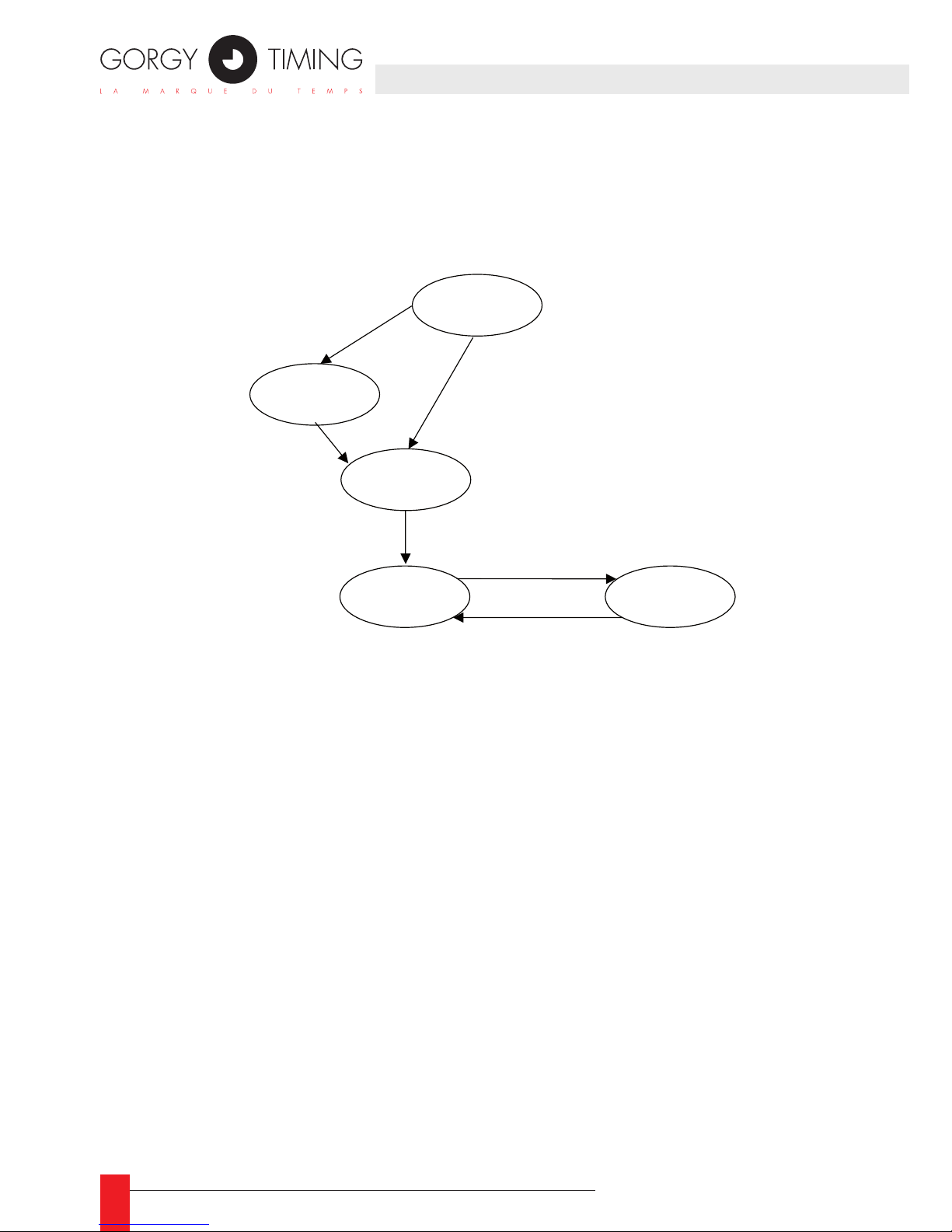
58
MDE-LEDI-NETWORK-IN-4065V1.0
1.3.2. The NTP client software
NTP software states
Here are the different states of the NTP client software:
Here is a description of these states:
Starting: ►
The software is starting, it initializes and check the hardware if needed.
Auto-detection: ►
Server auto-detection is activated. The NTP client tries to nd Gorgy Timing ser-
vers. At least one detected server is required to leave this state;
Learning: ►
The NTP client software has found one or several Gorgy Timing (auto-detection activated) or works with congured servers. In this state, the software learns network
properties. About 2 minutes are required to complete this stage;
Tracking: ►
Normal behavior, the NTP client permanently evaluate its offset and drift with the
server;
Commuting: ►
Not enough reply received from current server, trying another server.
1. INTRODUCTION
Starng
Auto-detecon
Learning
Tracking
Commung
Learning
environment
Searching servers
Enable outputs
No reply
Commuta�on OK
Learning
environment
Page 59

59
MDE-LEDI-NETWORK-IN-4065V1.0
2. FULL SETUP
This part contains information for a full conguration of the product. It should be
used for ne network conguration and output cards set-up
2.1. NETWORK CONFIGURATION
2.1.1. Default conguration
The LEDI Network IN is congured to automatically take an IP address from a DHCP
server. At startup, the product broadcast a DHCP query to get an IP address. This query
contains a DHCP name. There are two cases:
If a DHCP server is installed on the network, it record the DHCP name and return an ►
IP address. The LEDI Network IN starts working with this address.
If no DHCP server is installed, the LEDI Network IN automatically uses a default IP ►
address in the range 169.254.x.y (where x and y are between 0 and 255).
The default DHCP identier of the product is CRnnnnnn with nnnnnn, the serial number
on 6 digits. The serial number is written on the identication stamp on the top or on the
bottom of the product.
The default SNMP name of the product (that can be seen from a SNMP browser (see
part 6) or from a WEB browser) is LediNetwkINnnnnnn with nnnnnn, the serial number
on 6 digits.
2.1.2. Changing network parameters
Use the GTNetMng tool provided on the CDROM to congure your device:
Insert the CDROM in the drive. Start the GTNetMng tool that is localized in the ►
directory Common\Conguration
44
4/ For example, if your CD reader has letter E:, the GTNetMng tool is localized in E:\Common\Conguration\
GTNetMng.exe
ENGLISH
Page 60
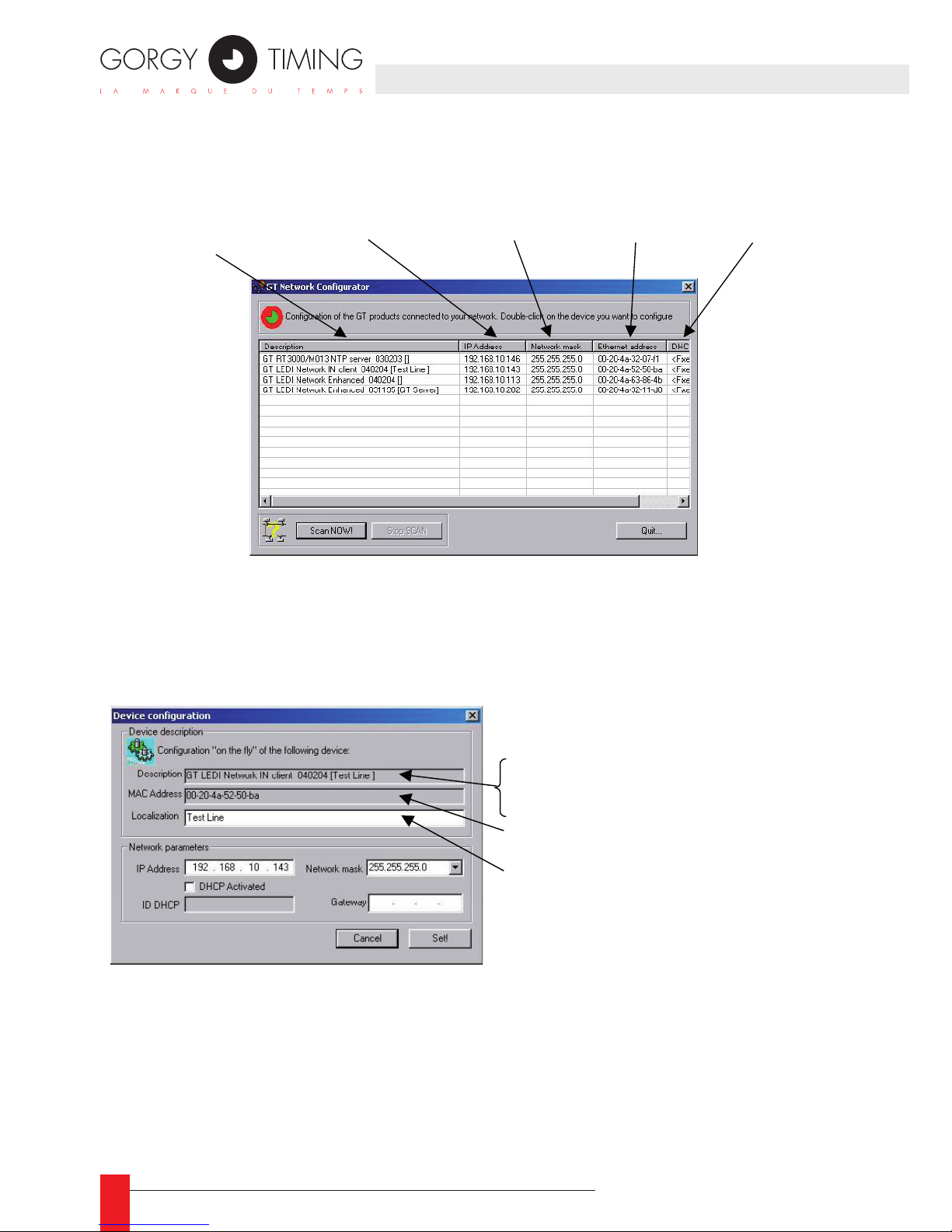
60
MDE-LEDI-NETWORK-IN-4065V1.0
The GTNetMng tool displays automatically the Gorgy Timing products installed ►
on your network. Each line contains information about one connected product as
shown below:
Double-click on the line related to the product you want to congure. The following ►
panel is displayed:
Set the network parameters and physical localization and click the Set! button. ►
Name, serial number
and localization
Current IP address
network mask
DHCP identifier
MAC address
Name of the device (GT LEDI Network IN)
Serial number (040204)
Localization (Test Line)
Ethernet (MAC) address of the
Localization of the product
Page 61

61
MDE-LEDI-NETWORK-IN-4065V1.0
2.1.3. Integration in your network
You don’t have to change any network setting for the following cases:
You have a DHCP server and enough reserved IP address for the product. ►
You don’t have a DHCP server but you don’t need to access to the device through ►
its WEB or SNMP interface. In this case, the AutoIP mechanism will automatically affect an IP address but this address will probably be incompatible with your
network.
Some DHCP servers have the capacity to register the device in the DNS. In this
case, the registered name is the DHCP identier. Then, you can access to the device
from your WEB or SNMP browser. For example if you give the DHCP name ntpin3 to
your LEDI Network IN, you can simply type ntpin3 in the address eld of your WEB
browser.
If you have several products to install on your installation, it is highly recommended to
follow the following steps:
Use the document provided in Appendix F – Additional documents (Summarized ►
installation view) and note the serial number and physical localization of each pro-
duct during the installation and connection;
On a PC connected on the same network that the products and start GTNetMng. All ►
the GT products should appears with their serial number. Set the network parameter
and localization using the document lled at previous step.
You can keep this document for further reference. ►
You can found the summarized installation view document in a WORD ☛
format on the CD ROM. Its full path is English\LEDI Network IN\docs\
installation.doc.
2. FULL SETUP
ENGLISH
Page 62
62
MDE-LEDI-NETWORK-IN-4065V1.0
2.2. OUTPUT CARDS CONFIGURATION
2.2.1. Introduction
Your LEDI Network IN is provided with up to 4 output cards. Each output card is tightly
synchronized on the NTP time code received from the NTP server. Each card acts as
a kind of translator that receives time from the NTP software and output specic time
code.
Currently, there are 6 kinds of cards:
ASCII+TOP RS232 (‘A’ type card) ►
ASCII+TOP RS485 (‘R’ type card). ►
AFNOR NFS 87500 / IRIGB (‘B’ type card). ►
AFNOR /IRIGB TTL / RS422 (‘T’ type card). ►
ALARM (‘G’ type card). ►
NTP server (‘N’ type card). ►
You can freely use and copy the table Devices conguration in Appendix F – Additional
documents.
2.2.2. Default conguration
When you receive this product from Gorgy Timing, all the output cards are congured to
output UTC time and time is constant all along the year (no Day Saving Time correction).
The display is managed as an output cards and can be congured in the same way..
2.2.3. Change the settings
Open the WEB site of the LEDI Network IN (see part 5). Click on the button.
The current conguration of your product appears at the screen (shown below for a 9257/
A model):
Page 63
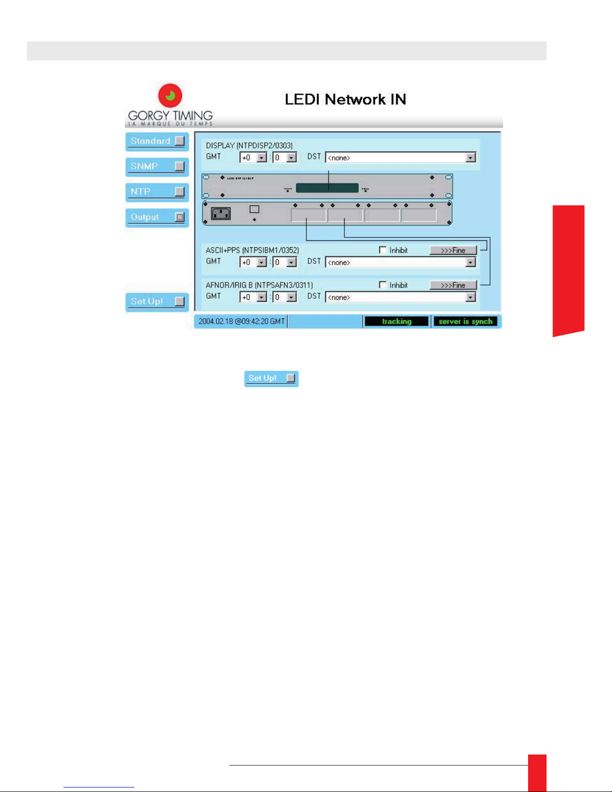
63
MDE-LEDI-NETWORK-IN-4065V1.0
In this screen you can tune each card independently (see part 5.2.5). When you have
change.the settings, click on the . button. The modication should appear immediately at the outputs or on the display.
2.2.4. NTP server output card conguration
You can add a NTP server output card to your LEDI network IN. By this way, you can
synchronize your local network on this card, which is itself synchronized by the NTP
client on a remote Internet NTP server.
The NTP server card has to be congured by the same way than the NTP client of the
LEDI Network IN. Its default network conguration is DHCP mode with identier SCnnnnnn with nnnnnn, the serial number on 6 digits.
The default SNMP name of the NTP server (that can be seen from a SNMP browser or
from a WEB browser) is NTPServnnnnnn with nnnnnn, the serial number on 6 digits.
To change the network parameters of the NTP server card, use the GTNetMng tool :
see page 10). Like the NTP client, the NTP server card provides a WEB page for ne
conguration (see page 31) and a SNMP MIB for supervision through the network (see
page 40).
2. FULL SETUP
ENGLISH
Page 64
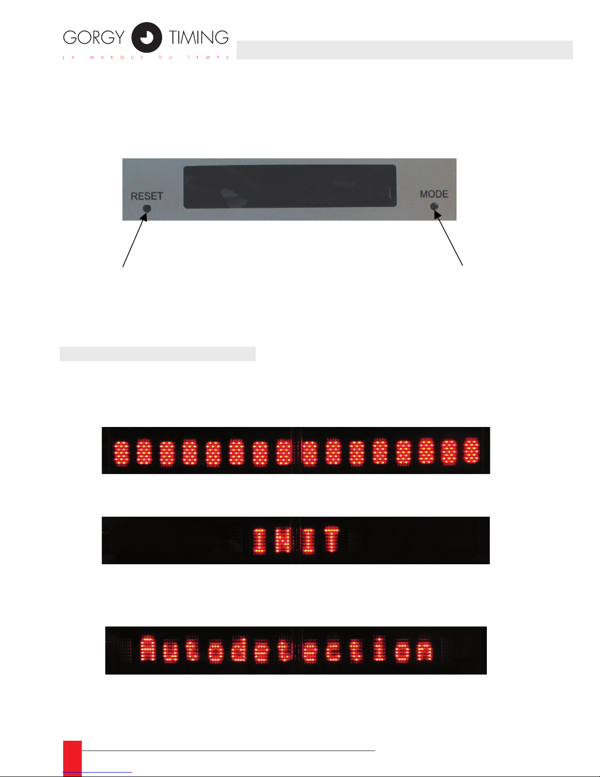
64
MDE-LEDI-NETWORK-IN-4065V1.0
The front display interface can display up to 16 characters. Two buttons provides
you with display conguration and global reset. The LEDI Network IN uses the front
display to show current time and different alarm condition.
3.1. START-UP CONDITIONS
During start-up, the time and date of the LEDI Network IN are not valid and are not displayed. Then, you can see the following texts:
When the device start, all the dots of the displays are lightened. ►
During hardware initialization, the following text is displayed. ►
If no server is congured by the user, the LEDI Network IN try to detect GT servers ►
and display the following message:
If the auto detection stage fails, the following text is displayed until a GT server is ►
available on the network:
Reset the LEDI
Network Enhanced
Switch between
UTC and LOCAL
time display
Page 65
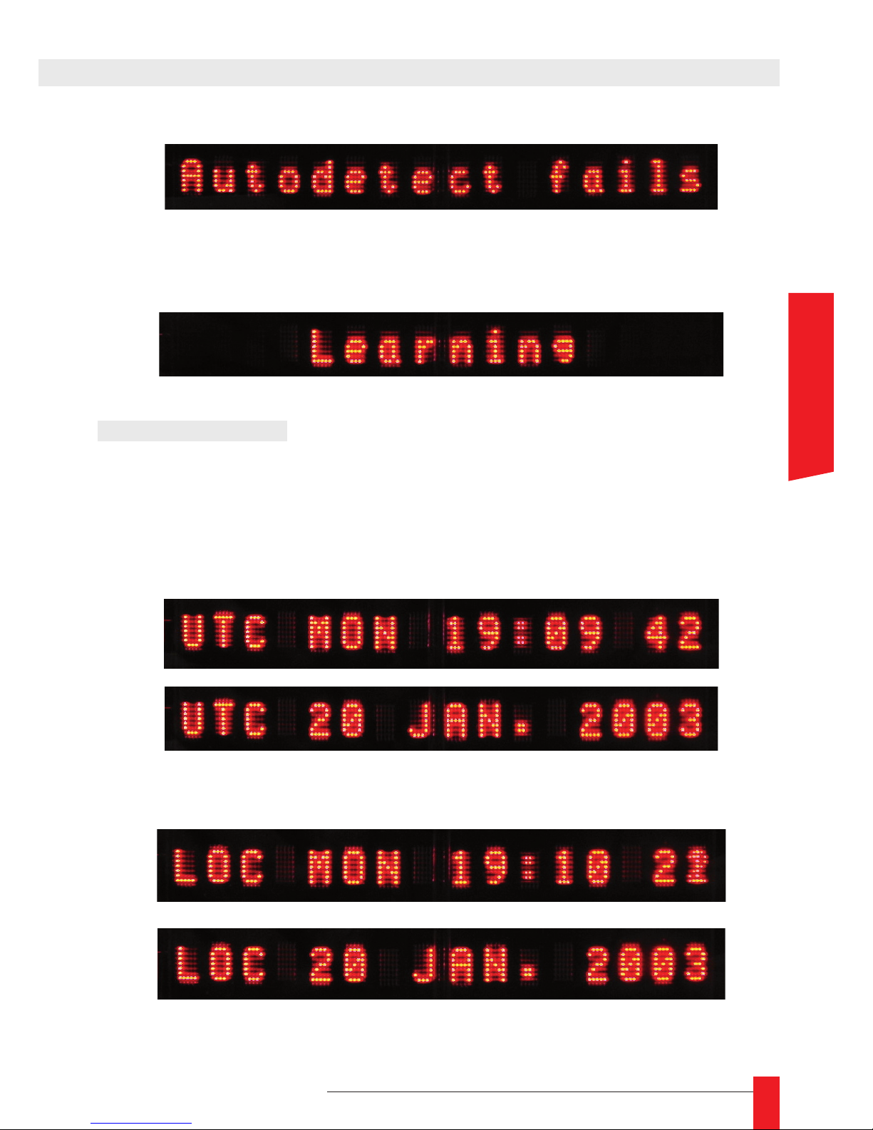
65
MDE-LEDI-NETWORK-IN-4065V1.0
If there is at least one GT server or the user has congured manually the servers, ►
the LEDI Network IN enters learning stage and displays the following text:
3.2. TIME DISPLAY
When no alarm is present and the LEDI Network IN is correctly synchronized on a server,
the current time of the server is permanently displayed. The display alternatively shows
time and date as shown below:
When displayed is congured to display UTC time, the following information are ►
alternatively displayed:
When displayed is congured to display local time, the following information are ►
alternatively displayed:
3. FRONT DISPLAY INTERFACE
ENGLISH
Page 66
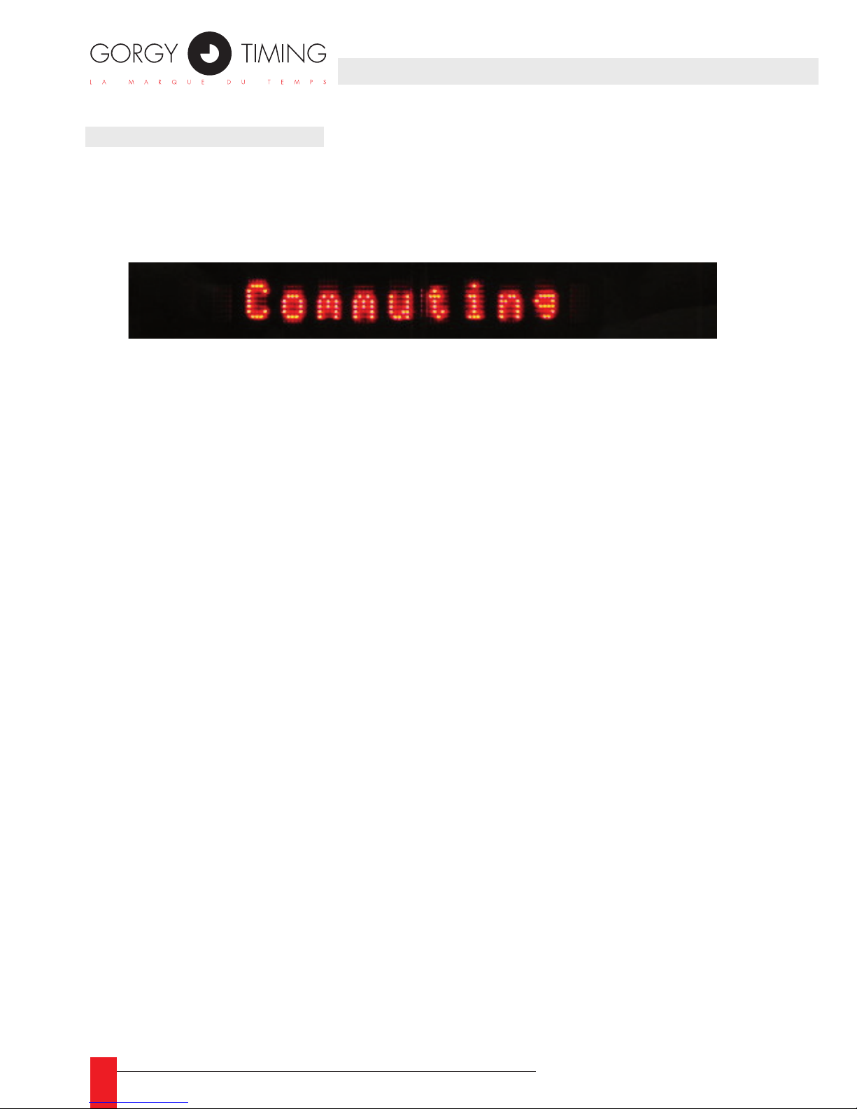
66
MDE-LEDI-NETWORK-IN-4065V1.0
3.3. ALARM CONDITION
The commuting alarm indicates that the server currently used for synchronization does not
reply (or does not reply correctly). In this case, the LEDI Network IN tries another server.
The display alternatively shows time (as described in previous part) and the following text:
Page 67
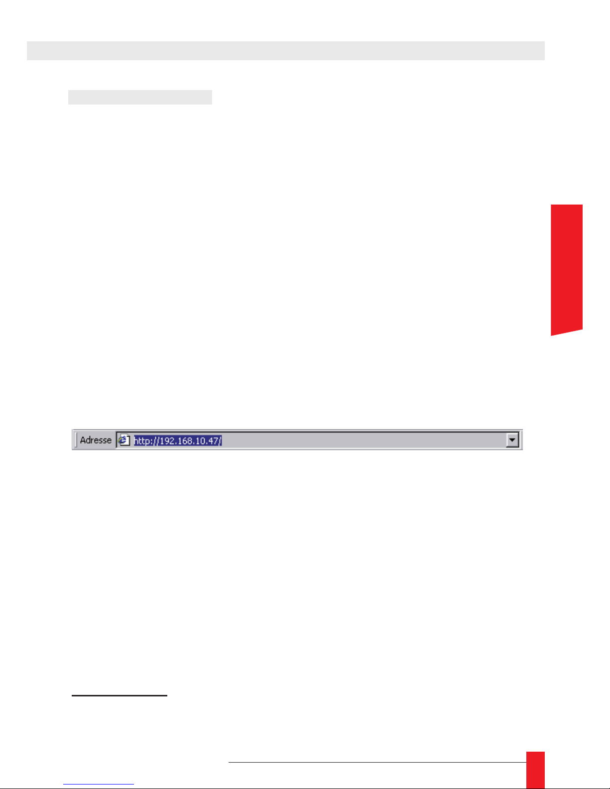
67
MDE-LEDI-NETWORK-IN-4065V1.0
4.1. PRESENTATION
The LEDI Network IN can be congured and supervised through a WEB interface. This
interface provides you with the following features:
Management of network parameters ►
Management of SNMP parameters ►
Management and diagnostic of NTP client software itself ►
Management and diagnostic of output cards. ►
Each LEDI Network IN has its own WEB server that delivers WEB pages. The WEB site
is a JAVA applet; if needed, you can nd a JVM on the CDROM in the directory Common\
JAVA.
To access the WEB site, type-in the address of the LEDI Network IN in the address eld of
your WEB browser (as shown below) and validate the input5.
It takes about 20 seconds to load of the JAVA applet. If the load fails, it can be for one of
the following reasons:
1. The IP address is invalid;
2. A network problem6 prevent your computer to contact the LEDI Network IN;
3. You don’t have a JVM engine installed on your computer.
For the rst two reasons, you have to check for the IP address of the LEDI Network IN and
your network conguration. For the last reason, you have to install the JVM (see directory
Common\JAVA on the CDROM).
5/ If you have congured your LEDI Network IN in DHCP mode and that your server automatically register DHCP
name in the DNS, you can also use the DHCP name instead of the IP address
6/ Check especially the conguration of your Internet Explorer.
4. WEB INTERFACE
ENGLISH
Page 68
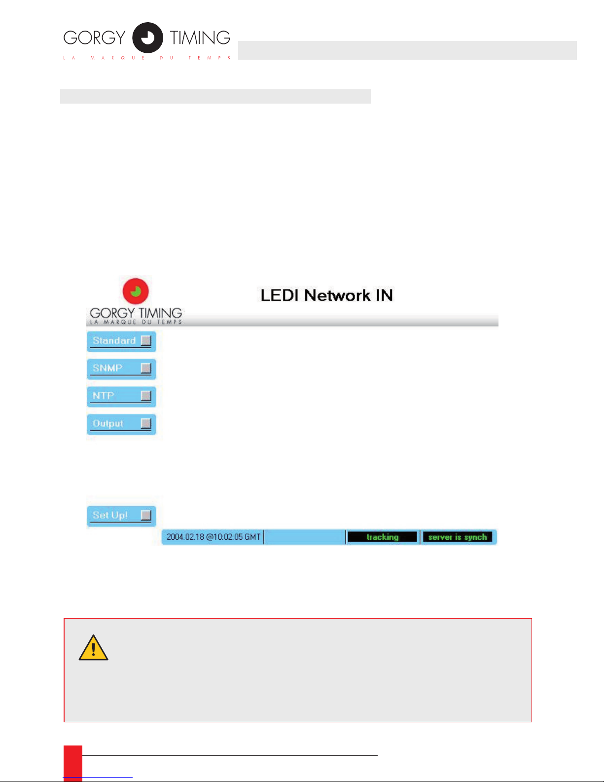
68
MDE-LEDI-NETWORK-IN-4065V1.0
4.2. DESCRIPTION OF THE WEB INTERFACE
4.2.1. Ecran Principal
This is the screen that appears when accessing the WEB site of the LEDI Network
IN. The rst four buttons at the left of the screen provide an access to the following
panels:
1. Standard: information about the product and conguration of network parameters
See part 2.2.
2. SNMP: conguration of SNMP parameters;
3. NTP: diagnostic and conguration of the NTP software behavior;
4. Output: diagnostic and conguration of output cards and display.
The Set Up! button updates immediately the LEDI Network IN conguration. The con-
guration is stored permanently in an EEPROM.
WARNING. Some parameters cannot be modied without restarting
the LEDI Network IN. If you change these kind of parameters and
click on the Set Up! button, the LEDI Network IN restarts with the
new parameters and needs 2 minutes before re-enable its outputs.
Page 69
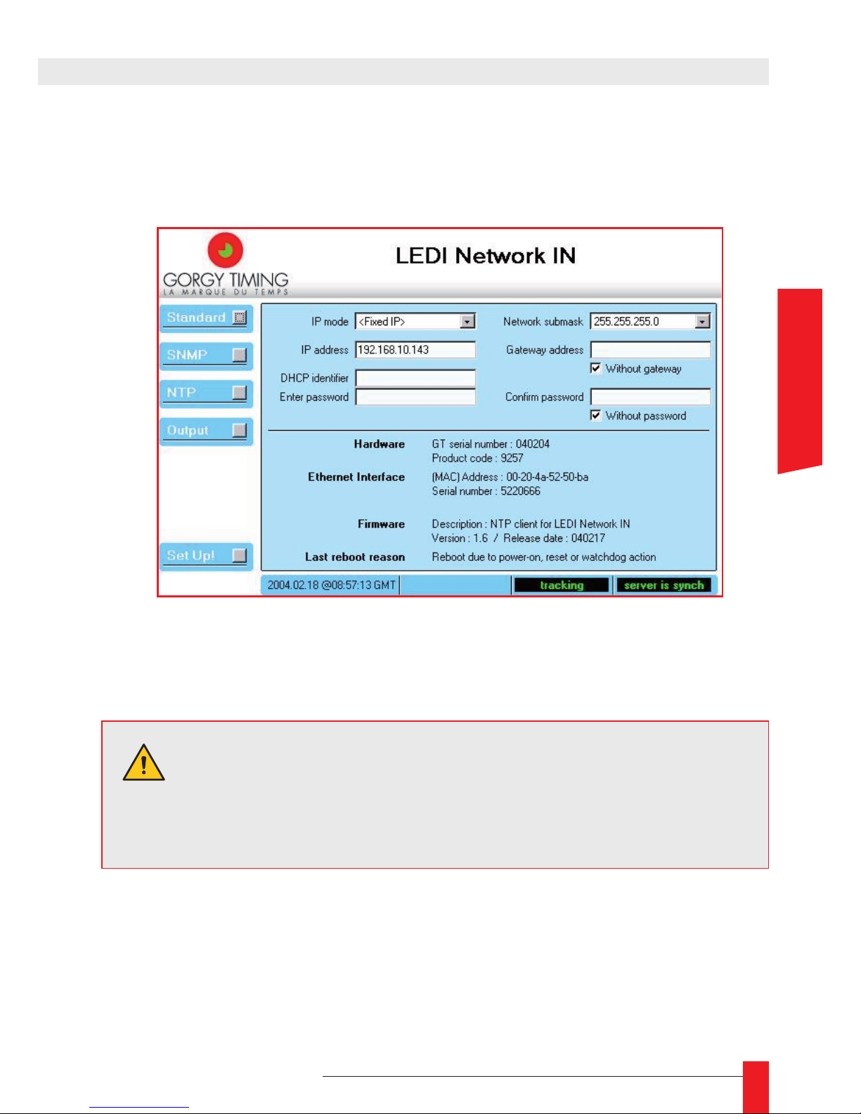
69
MDE-LEDI-NETWORK-IN-4065V1.0
4.2.2. Standard setup
When you click the Standard button, the network parameters and product information
are displayed as shown below:
In the top of the panel, you can control the network parameters and the WEB access
password. In the bottom of the panel, you have information about the product.
NETWORK PARAMETERS
Here are the different parameters:
IP mode ►
Indicate if the LEDI Network IN works with a xed IP (set in the eld IP address) or
use DHCP protocol (the DHCP identier is set in the eld DHCP identier);
WARNING. If you click on the Set Up! button after changing one or
several network parameter(s), the LEDI Network IN must restart to
use the network parameters. During the reset and 2 minutes after,
the output(s) of the product is(are) disabled.
4. WEB INTERFACE
ENGLISH
Page 70
70
MDE-LEDI-NETWORK-IN-4065V1.0
IP address ►
Indicate the network address affected to the device. An IP address is made of four
numbers separated by a dot. Each number range from 0 to 255;
DHCP identier ►
Identier to be used when the LEDI Network IN is congured in DHCP mode. This
identier has 8 letters maximum. The default value is CRnnnnnn (where nnnnnn is
the serial number on 6 digits);
Network submask ►
Indicate the width of the network you use. For example, a network submask
255.255.255.0 indicates that only the last number change (in the example above,
address in the network can change between 192.168.10.1 to 192.168.10.254)7.
Gateway address ►
If you want the LEDI Network IN to communicate with devices outside the local
network, you must indicate a gateway that will be used to go outside local network;
Without gateway ►
Check this box when you don’t have a gateway on your network (or don’t want to
use it);
PRODUCT INFORMATION
Here is a description of the product information area:
Hardware ► GT serial number
Display the Gorgy Timing serial number of the product. This is a 6 digits number
which is the same than the one stamped on the bottom or background of the rack
Hardware ► Product code
Display the Gorgy Timing base code of the product without option (9257 for a LEDI
Network IN)
Ethernet Interface ► (MAC) Address
Indicate the Medium Access address of the Ethernet interface of the LEDI Network IN
Ethernet Interface ► Adapter Serial number
Indicate the serial number of the Ethernet interface of the LEDI Network IN. This
information can be useful for maintenance;
Firmware ► Description
Short text that describes which software is running on your product
7/ If you congure several devices to communicate on the same network, you must have the same network submask.
Page 71
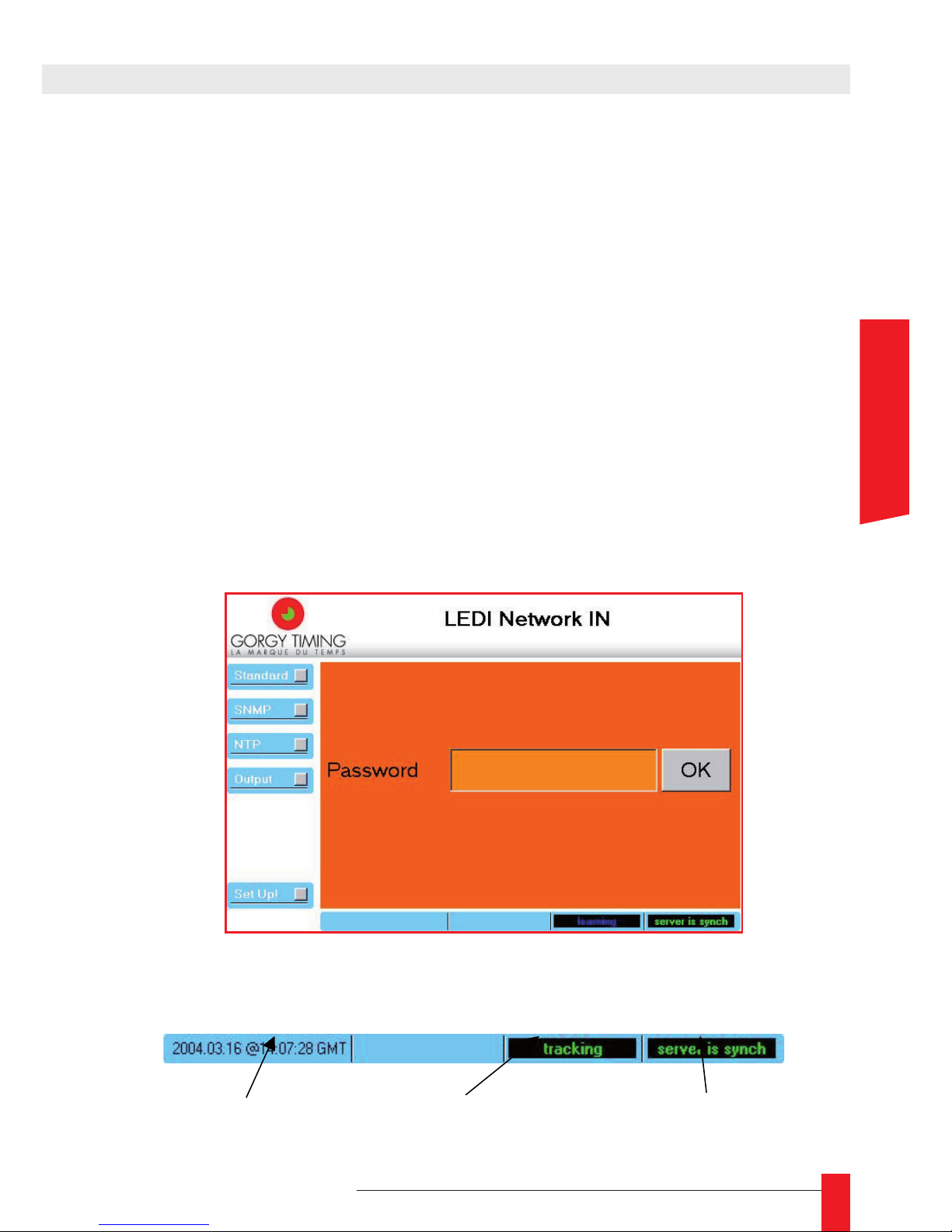
71
MDE-LEDI-NETWORK-IN-4065V1.0
Firmware ► Version/Release Date
Version of the software running in the LEDI Network IN and date of the last produced software (in English format yymmdd for example 021010 for 2002, October the
10th);
Last reboot reason ►
A text that Indicates why the LEDI Network IN has restarted the last time.
WEB SITE ACCESS PROTECTION
If you want to protect access to the parameters of the LEDI Network IN, you can specify
a password. This is done by enter the password twice in the area Enter password and
Conrm password (the same password in the two areas).
If you don’t want to protect the parameters, check the box Without password.
When a password is set, it will be asked to the user at the next connection. In this case, the
main screen looks like follows:
STATUS BAR
The status bar is positioned on bottom of the WEB page. It gives information about the NTP
client software. It contains the following information:
4. WEB INTERFACE
Current UTC time
received from NTP
Current state of
NTP software
Current state of remote NTP
server synchronization
ENGLISH
Page 72
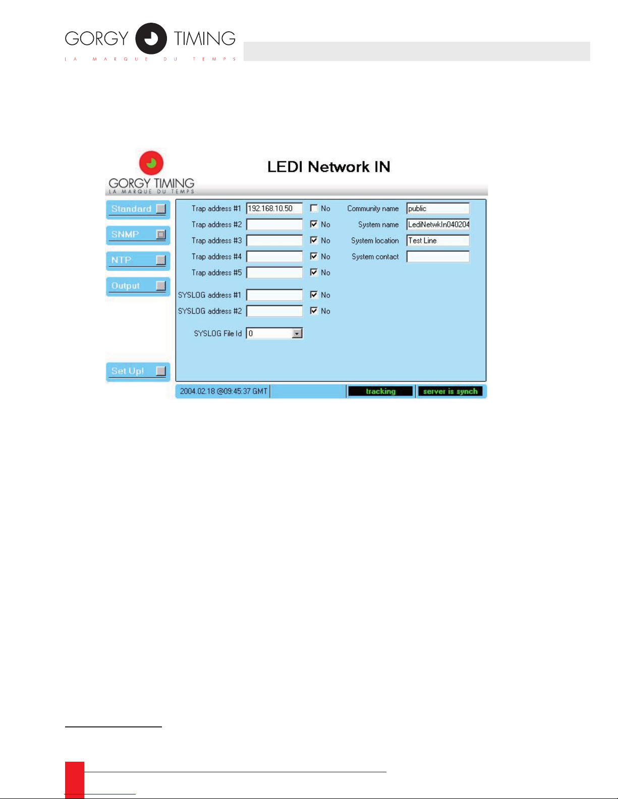
72
MDE-LEDI-NETWORK-IN-4065V1.0
4.2.3. SNMP setup
When you click the SNMP button, the SNMP parameters are displayed as shown below:
The very standardized SNMP protocol provides a means to get information and alarms
from the LEDI Network IN.8 Access to these information (the MIB) can be “protected” by
a keyword that is the Community Name.
Alarms are sent to a SNMP browser localized on a computer identied by its IP ad-
dress. Up to 5 IP Trap address can be specied that allows the alarm monitoring from
5 different computers.
Last, the SNMP related name, location and contact could be congured in this screen.
These information are stored in the system branch of the MIB and can be displayed in
a SNMP browser or in the GTNetMng tool (see part 31.2).
For convenience, alarms can be notied through the SYSLOG protocol that is more
often implemented under UNIX®.
8/ See part 6 for more information about SNMP
Page 73

73
MDE-LEDI-NETWORK-IN-4065V1.0
DESCRIPTION
Here is a description of the elds in this panel:
Trap address #1...#5 ►
Address(es) of the computer(s) to which will be sent the SNMP alarm notication.
When you don’t use an address, you must check the related No box;
SYSLOG address #1...#2 ►
Address(es) of the computer to which will be sent the SYSLOG alarm notication.
When you don’t use an address, you must check the related No box;
SYSLOG File Id ►
Identify the le to use on remote computer for SYSLOG protocol;
Community name ►
A simple keyword that is needed in a SNMP browser to access SNMP information.
This keyword must have 8 letter at the most;
System name ►
A text that you can use to give a name to the LEDI Network IN. This name appears
in the sysName variable of the system branch of the MIB. The initial value is Ledi-
NetwkINnnnnnn (where nnnnnn is the serial number of the product);
System location ►
A text that you can use to indicate the physical localization of the LEDI Network IN.
This name appears in the sysLocation variable of the system branch in the MIB.
There is no initial value.
System contact ►
A text that you can use to indicate the person to contact for any problem related to
this LEDI Network IN. This name appears in the sysContact variable of the system
branch in the MIB. There is no initial value.
dentie le chier à utiliser sur l’ordinateur distant pour le protocole SYSLOG.
4. WEB INTERFACE
ENGLISH
Page 74
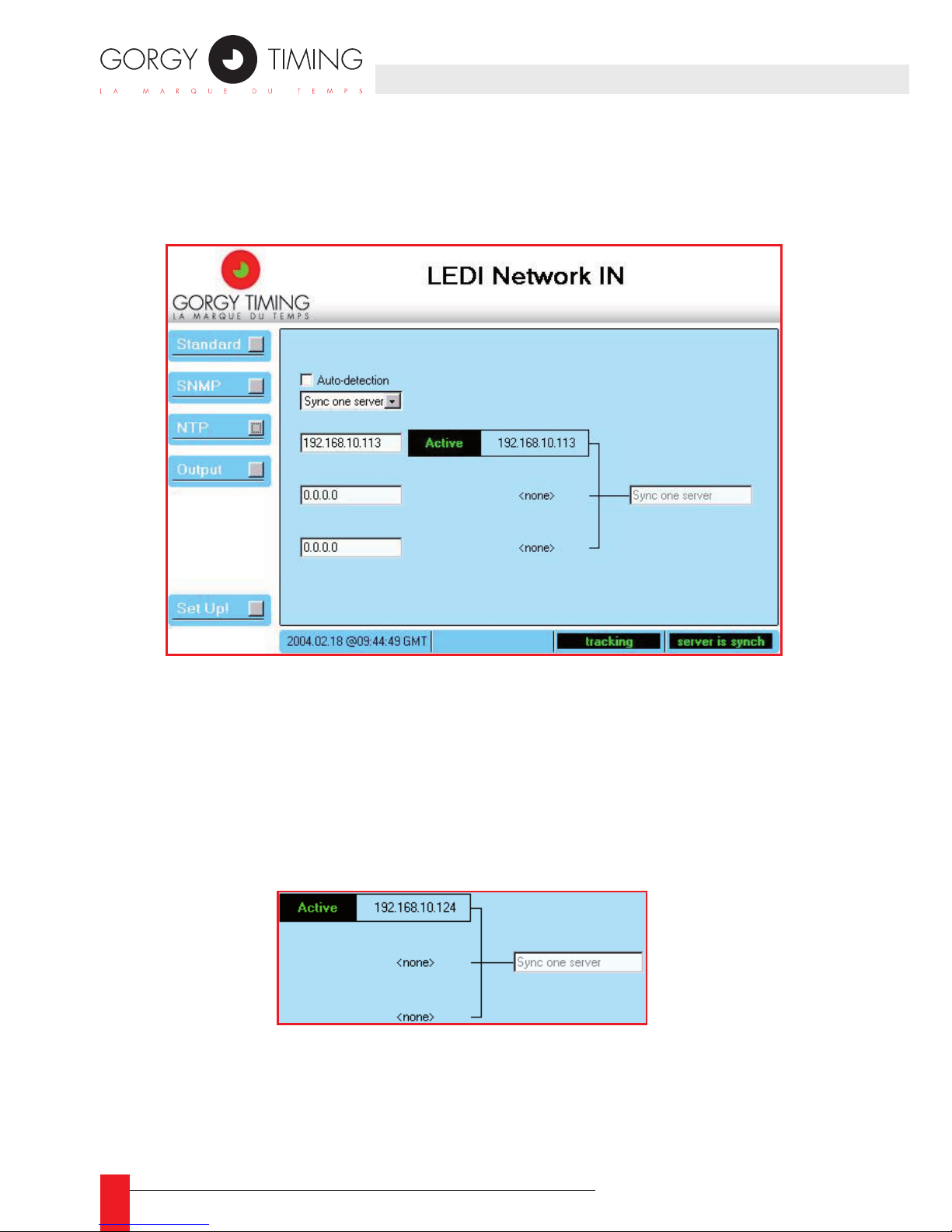
74
MDE-LEDI-NETWORK-IN-4065V1.0
4.2.4. NTP Setup
When you click the NTP button, the conguration of the synchronization of the LEDI
Network IN is displayed as shown below:
The LEDI Network IN can be synchronized on up to three NTP servers. In fact, the NTP
software uses only one server at the same time but can commute to another server
when there is no or not enough reply.
The NTP conguration panel shows what is the synchronization mode used by the
server or selected by the NTP software. It also shows the servers dened by the user
or detected by the software
DESCRIPTION
The right part of this screen shows the current conguration used by the NTP client
software:
IIt shows the different servers used for synchronization and the current synchronization
mode (on the screenshot above, there is only one server at IP address 192.168.10.124).
In addition, this screen part shows what is the server currently used for synchronization
(with a frame labeled Active). If a commutation is in progress, the label Trying is dis-
played nears the related NTP server. :
Page 75
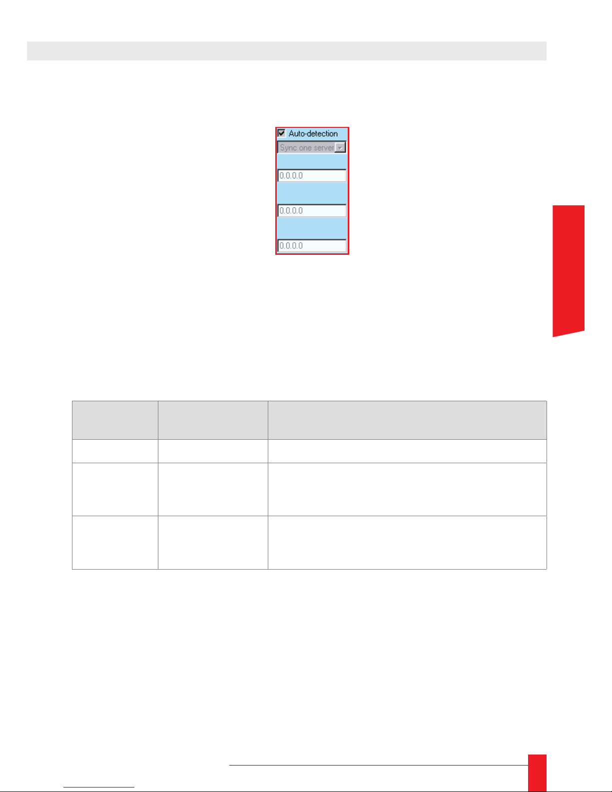
75
MDE-LEDI-NETWORK-IN-4065V1.0
The left part of the NTP screen allows you to congure the synchronization mode and
the NTP servers used:
If you select the checkbox Auto-detection, the LEDI Network IN try to use the GT NTP
servers present on your network and use the more appropriate synchronization mode.
If you don’t select the checkbox Auto-detection, you have to indicate the synchroniza-
tion mode and the NTP servers to use.
The following table can help you to select the more appropriate parameters:
Mode
# of NTP servers
used
Description
One server 1 Use only one server for synchronization
Two servers 2
Use the rst server at startup. If this server fails,
commute to the second server. If this server fails,
commute to the rst one and so on…
Three servers 3
Use the rst server at startup. If this server fails,
commute to the second server. If this server fails,
commute to the third one and so on…
4. WEB INTERFACE
ENGLISH
Page 76
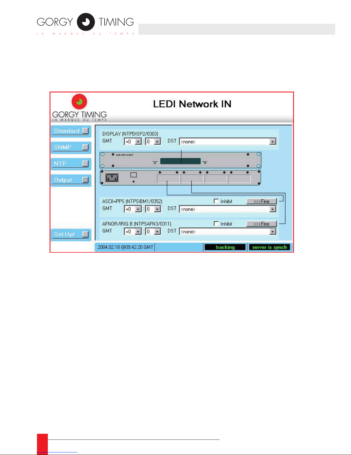
76
MDE-LEDI-NETWORK-IN-4065V1.0
4.2.5. Output and display setup
When you click on the Output button, the conguration of the output of the LEDI Network
IN is displayed as shown below:
This panel shows a synthetic view of the outputs of the product. The display is considered as an output and is driven by a display card. A LEDI Network IN can contain up to 4
output cards plus the display card.
The display and each output cards can be congured independently using the right
cyan box. When an output card is not present or in failure, its box doesn’t appear.
At this time, there are 6 kinds of output cards:
• ASCII+TOP RS232 (‘A’ type card).
• ASCII+TOP RS485 (‘R’ type card).
• AFNOR NFS 87500 / IRIGB (‘B’ type card).
• AFNOR /IRIGB TTL / RS422 (‘T’ type card).
• ALARM (‘G’ type card);
• NTP server (‘N’ type card).
You can freely use and copy the table Devices conguration in Appendix F – Additional
documents.
Page 77
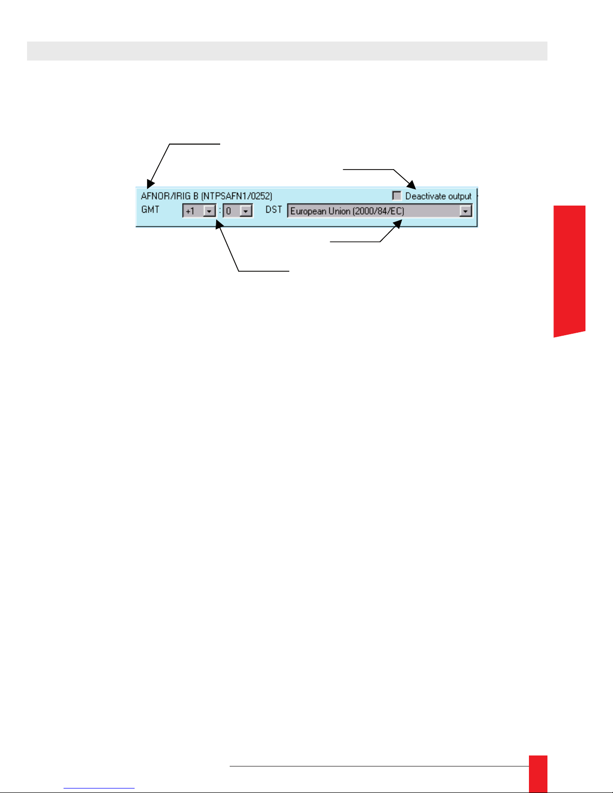
77
MDE-LEDI-NETWORK-IN-4065V1.0
STANDARD OUTPUT CONFIGURATION
The previous picture shows the conguration panel for an AFNOR/IRIG-B. In addition,
the description contains identication and version of the program embedded in the output card (there, it’s the program NTPSAFN1, version 0252).
Each output card can be congured independently through the following parameters :
Output deactivation ►
Except the display, all the output cards can be deactivated. The deactivation has
the following effects :
For ASCII+TOP card, the time frame is not generated and the TOP outputs are ►
in the open state;
For AFNOR output, the carrier is not modulated. ►
The ALARM output doesn’t generate warning signal. ►
Time Zone ►
The “Time Zone” is a time offset that can be added or subtracted from the time
received through the NTP protocol (which is UTC time) to generate local time. For
example in France, local time is GMT + 1:00.
Day Saving Time ►
In addition to the Time Zone, many countries apply a Day Saving Time correction.
The year is made of two areas: in summer time, 1 hour more is added to the time
(after Time Zone correction), in winter time only the Time zone correction is applied.
Don’t forget to select the appropriate country in the WEB interface.
4. WEB INTERFACE
Description & name of the card
Disable the output
Offset to apply to UTC time
DST Policy
ENGLISH
Page 78
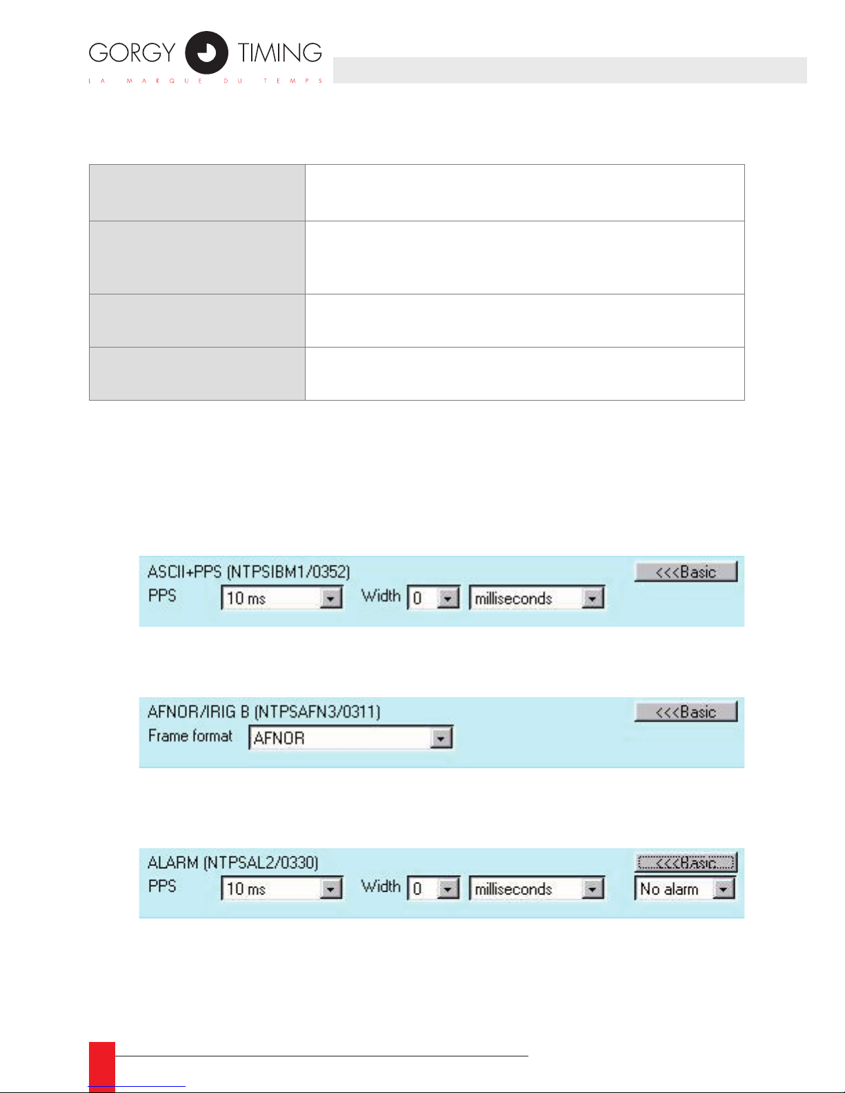
78
MDE-LEDI-NETWORK-IN-4065V1.0
Here are the different DST policies :
FINE OUTPUT CONFIGURATION
Some output cards provide specic conguration :
ASCII + PPS ne conguration : ►
You can congure here the period and the width of the TOP.
AFNOR / IRIG-B ne conguration : ►
Choose your frame format : Afnor, Irig-B or Irig-B + binary second.
ALARM ne conguration : ►
To congure the different alarm signals, choose an alarm type (no alarm, synchronization
failure, power failure, synchronization + power failure) then set the period and width of
the signal. Do the same for each alarm type.
European Union
Start: Last Sunday in March at 1 am UTC
End: Last Sunday in October at 1 am UTC
USA / Canada / Mexico
/ St. Johns / Bahamas /
Turks / Caicos
tart: First Sunday in April
End: Last Sunday in October
Australia – Standard
Start: Last Sunday in October
End: Last Sunday in March
Russia
Start: Last Sunday in March at 2 am local time
End: Last Sunday in October at 2 am local time
Page 79
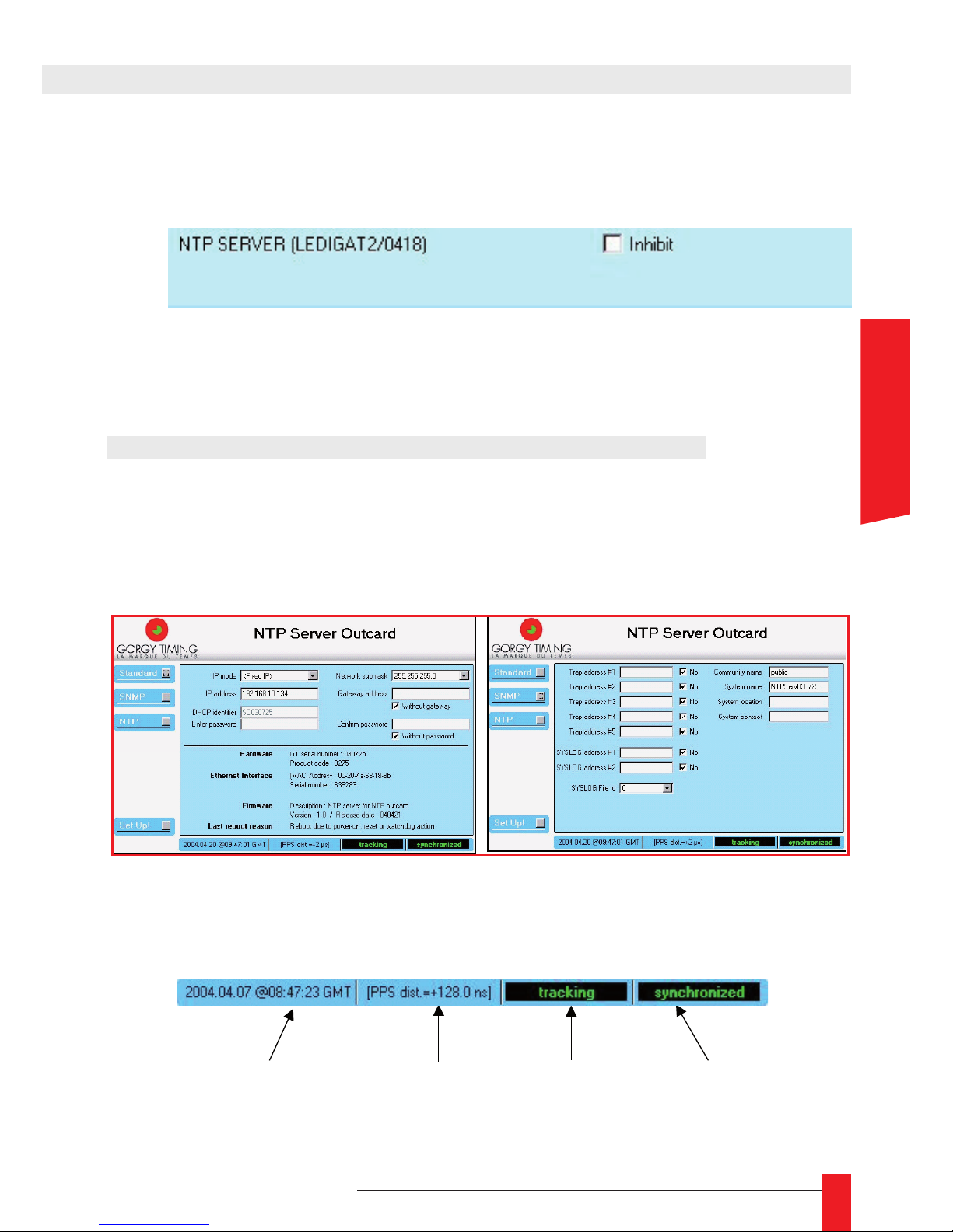
79
MDE-LEDI-NETWORK-IN-4065V1.0
4. WEB INTERFACE
NTP SERVER OUTPUT CONFIGURATION
If your product is provided with a NTP server card, the following panel will be displayed:
Offset from UTC cannot be congured, as the card deliver NTP time code in UTC. To
congure nely the NTP server card, you need to open its own WEB page, described
in the following chapter.
4.3. WEB INTERFACE OF NTP SERVER OUTPUT CARD
4.3.1. Network and SNMP setup
To congure network and SNMP parameters, the NTP server output card provides the
same WEB panels than the LEDI Network IN (see below). Please refer to parts 2.2 and
2.3 for more details. The NTP server MIB is detailed in page 40.
Status bar
The status bar is positioned on bottom of the WEB page. It gives information about the NTP
server software. It contains the following information:
Current UTC time
delivered through NTP
Phase difference
between software clock
and time code
delivered by hardware
Current state of
NTP software
Synchronization
state
ENGLISH
Page 80
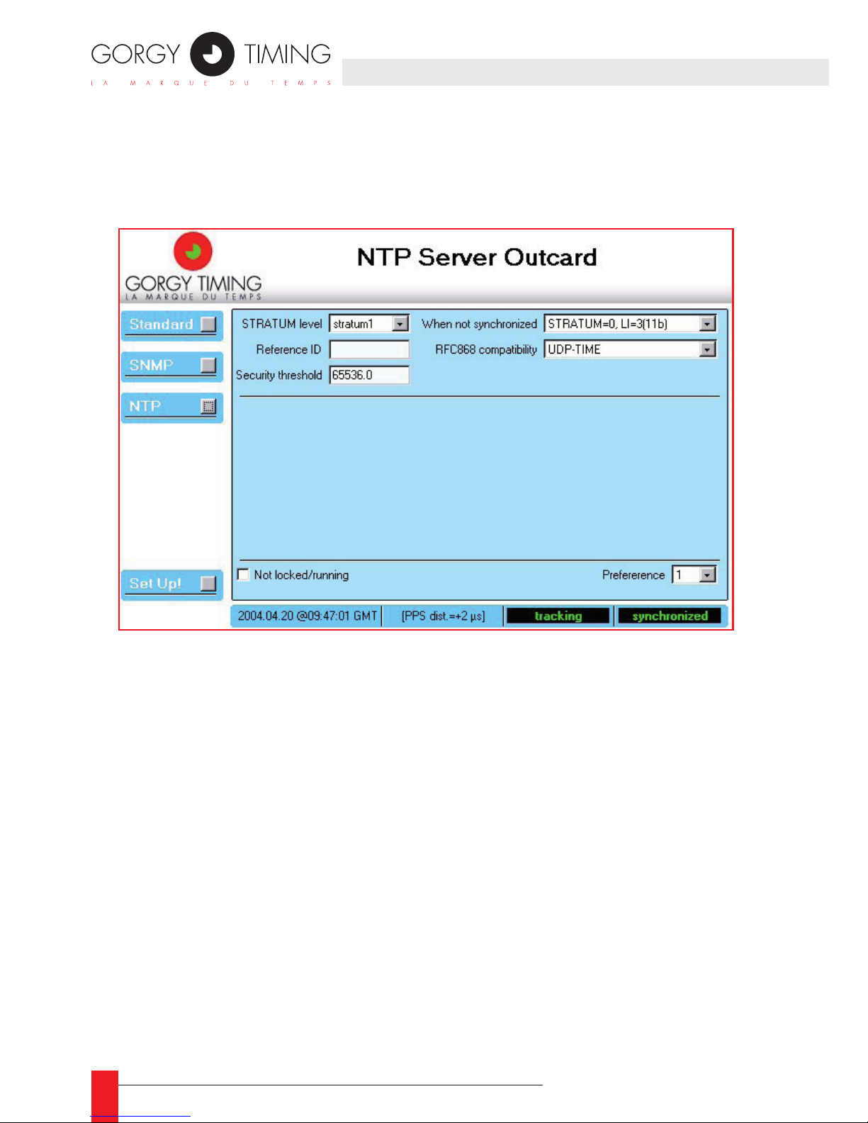
80
MDE-LEDI-NETWORK-IN-4065V1.0
4.3.2 NTP setup
When you click the NTP button, the conguration of the NTP server software of the
output card is displayed as shown below:
Description
Here is the short description of the different elds:
STRATUM level ►
the stratum value to be stored in the NTP messages sends to the NTP clients.
Reference ID ►
A 4 letters identier that gives information about the time reference. This value is put
in the appropriate eld in the NTP frame
Security threshold ►
Give the maximum allowed phase difference (in seconds) before locking the NTP
server software. This eld is initialized to 65536.0
Page 81

81
MDE-LEDI-NETWORK-IN-4065V1.0
4. WEB INTERFACE
When not synchronized ►
Dene the effect on some NTP elds when the LEDI Network Enhanced is not
synchronized9. The possible values LI&STRATUM unchanged, STRATUM=0,LI un-
changed, STRATUM unchanged, LI=3(11b), STRATUM=0, LI=3(11b)
RFC868 compatibility ►
Specify the kind of compatibility with RFC868 : Not compatible, UDP Time server
or TCP Time server
Lock control ►
This checkbox allows the user to control the lock state of the LEDI Network Enhanced. When checked, the NTP server is locked and doesn’t deliver NTP or output
signal. When cleared the NTP server is working.
Preference ►
A number that allow you to prioritize your different Gorgy-Timing NTP servers. By
this way, the server with the highest preference number is chosen in priority by
Gorgy-Timing NTP clients.
9/ Time code is not present (server is autonomous) or the received time-code indicates that external synchronization is lost
ENGLISH
Page 82
82
MDE-LEDI-NETWORK-IN-4065V1.0
5.1. PRESENTATION
The LEDI Network IN provides a SNMP v1 interface for ne monitoring and diagnostic.
The SNMP protocol allows the supervision of a device through the network. Two kind of
information are available through a SNMP interface:
A set of variables that can be read. These variables are stored together in a databa- ►
se (MIB) organized in a hierarchical way. The variables are set by the NTP software
to reect its internal states.
Some traps that can be generated by the NTP software to indicate important state ►
modication.
There is two important parts in the MIB:
A general-purpose branch named System. This branch is MIB II compatible. ►
A private branch that contains information specic to the LEDI Network IN product. ►
Private MIBs are described with .MIB les. Two .MIB les are provided on the CDROM in
the directory English\LEDINETWORKIN\MIB:
The le GtNtpOutBus.mib contains the description of the information related to the ►
output cards – Localization in the MIB:
iso(1).org(3).dod(6).internet(1).private(4).enterprises(1).gorgy(8955).hardware(2).ntpOutBus(1)
The le GtNtpClient.mib contains the description of the information related to the ►
NTP client software – Localization in the MIB:
iso(1).org(3).dod(6).internet(1).private(4).enterprises(1).gorgy(8955).software(1).ntpClient(4)
The le GtNtpServer.mib contains the description of the information related to the ►
NTP server output card software – Localization in the MIB:
iso(1).org(3).dod(6).internet(1).private(4).enterprises(1).gorgy(8955).software(1).ntpSrv(3)
5. SNMP INTERFACE
Page 83
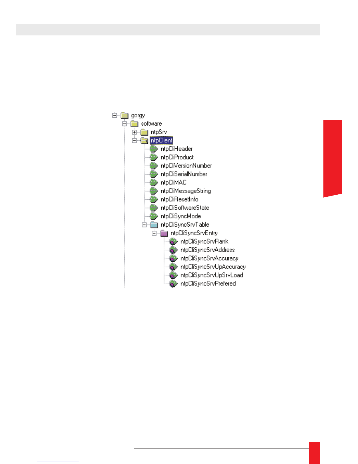
83
MDE-LEDI-NETWORK-IN-4065V1.0
5. SNMP INTERFACE
5.1.1. Structure of the private MIB for LEDI Network IN
SOFTWARE
This branch contains all the information related to the client software itself. Here is the
structure of this branch:
The different elds of this branch are described below:
ntpCliHeader ►
A short description of the product. It should be something like GT LEDI Network IN
client nnnnnn Vxx.yy (yymmdd) where xx.yy is the current version of the software,
yymmdd is the release date of the software (dd/mm/yy) and nnnnnn is the serial
number of the product.
• ntpCliProduct ►
A description of the product with its options that should be similar to the product
code (described in Erreur ! Source du renvoi introuvable.). For example 9257/
AB........D indicates a LEDI Network IN with IRIG-B and ASCII outputs and a display
(code D).
ENGLISH
Page 84
84
MDE-LEDI-NETWORK-IN-4065V1.0
ntpCliVersionNumber ►
Version of this product. It’s something like Vxx.yy (yymmdd) where xx.yy is the
current version of the software, yymmdd is the release date of the software (dd/
mm/yy)
ntpCliSerialNumber ►
Serial number of this product on 6 digits.
ntpCliMAC ►
Hardware address of the Ethernet interface of the LEDI Network IN. This address is
on the form aa:bb:cc:dd:ee (6 binary bytes).
ntpCliMessageString ►
A text that gives the description of the last generated trap. This text is also attached
to the trap.
ntpCliResetInfo ►
A text that indicates why the product has restarted (reconguration or hard reset).
ntpCliSoftwareState ►
This eld gives the current state of the NTP client software. It can take one of the
following values:
Idle: the product has just started. ►
Autodetection: no NTP server has been specied and the product is trying to ►
detect NTP server(s).
Autodetectfail: no NTP server found for synchronization – the product will use a ►
server as soon as you connect a server on your network.
Learning: the software is currently learning network properties. ►
ntpCliSyncMode ►
The synchronization mode currently used. It can be one of the following values:
Autodetect: no NTP server has been specied and the product is trying to detect ►
NTP server(s).
Sync1server: works with only one NTP server. ►
Sync2server: works with two NTP servers. When a server fails, it uses the other ►
one.
Sync3server: works with 3 NTP servers. When a server fails, it uses one of the ►
other servers.
Page 85

85
MDE-LEDI-NETWORK-IN-4065V1.0
ntpCliSyncSrvTable ►
A table that contains all the servers used for synchronization and information. First
entry in the table is server being used for synchronization. Second entry is the preferred second server, etc. Each entry has the following format:
ntpCliSyncSrvRank: ►
rank of the server. Server of rank 1 is used for synchronization.
ntpCliSyncSrvAddress ► :
IP address of the server.
ntpCliSyncSrvAccuracy: ►
Accuracy of the server as returned in the NTP frame (something like 2^-x se-
conds).
ntpCliSyncSrvUpAccuracy (Gorgy Timing server only) ►
Accuracy of the server as returned during auto-detection stage.
ntpCliSyncSrvUpSrvLoad (Gorgy Timing server only) ►
Load of the server (average number of requests per second) as returned during
auto-detection stage.
ntpCliSyncSrvPrefered (Gorgy Timing server only) ►
A number that indicates a user-dened rank attached to this server. When auto-detection is activated, the LEDI Network IN takes the server with higher rank.
5. SNMP INTERFACE
ENGLISH
Page 86
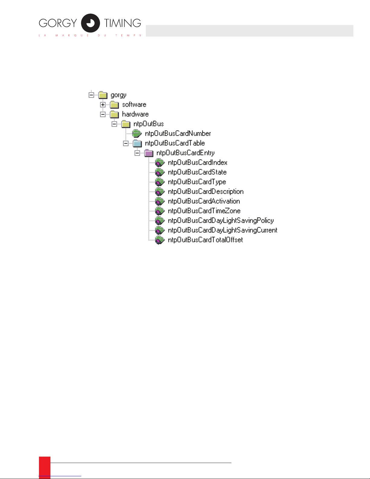
86
MDE-LEDI-NETWORK-IN-4065V1.0
HARDWARE
The MIB describes which card is detected and what is the conguration for the cards.
All the output cards and the display are connected to a same output bus.
The different elds of this branch are described below:
ntpOutBusCardNumber ►
Number of cards detected on output bus.
ntpOutBusCardTable ►
A table that shows all the cards detected on the output bus. Each card is indexed by
its address (1..8 for output cards and 9 for the display). Each entry has the following
format:
ntpOutBusCardIndex: ►
Index of this entry (i.e card address). This value can have a value from 1 to 8 (for
output cards) or 9 (for display);
ntpOutBusCardState: ►
The state of the card. It can be detected that indicate that the card works cor-
rectly, failure if the card don’t reply or scrambled if the reply from the card is
incorrect;
ntpOutBusCardType: ►
Type of the card (see Erreur ! Source du renvoi introuvable. for a list of the
possible output cards types);
ntpOutBusCardDescription: ►
A textual description of the card;
Page 87
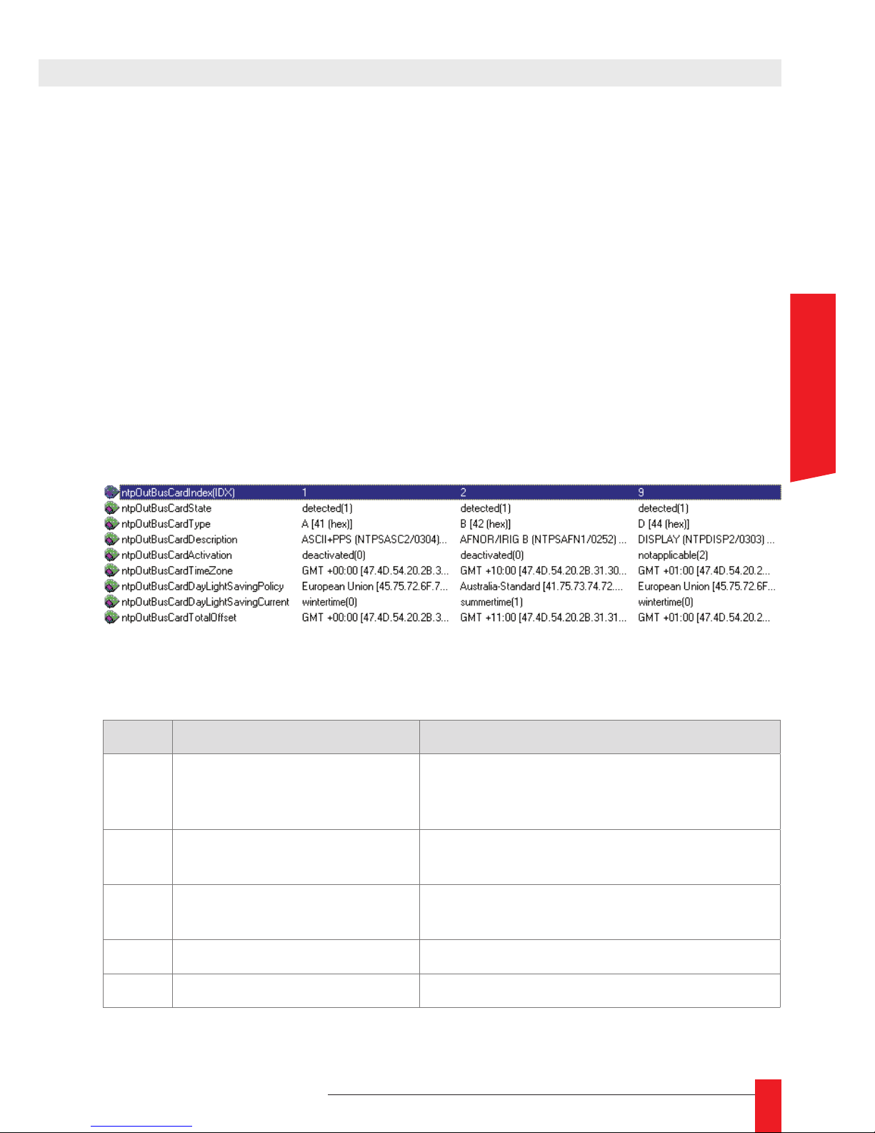
87
MDE-LEDI-NETWORK-IN-4065V1.0
ntpOutBusCardActivation: ►
Indicate if the output of the card activated or deactivated (this feature can be
controlled from the WEB interface). If the card cannot be deactivated, this eld
has the value notapplicable;
ntpOutBusCardTimeZone: ►
Time-zone for this output. This is displayed as an offset from universal time. This
setting can be changed from the WEB interface;
ntpOutBusCardDayLightSavingPolicy: ►
Indicate which day saving time policy is used. If there is no DST, this eld has
the value <none>. This setting can be changed from the WEB interface;
ntpOutBusCardDayLighSavingCurrent: ►
Indicate if Day Saving Time is in effect (value summertime) or not (value wintertime). If Day Saving Time is not activated, this eld has the value notapplicable;
ntpOutBusCardTotalOffset: ►
Indicate current total offset from UTC.
Here is an example of the description of the output cards displayed in a SNMP browser:
5.1.2. Description of the SNMP traps
# Related MIB variable Alarm meaning
1
2
3
ntpCliAutoCong
ntpCliAutoCongDone
ntpCliAutoCongFail
Auto conguration of the NTP client (NTP
servers searching) : starting, done or fail
4 ntpCliLearning The NTP client begins is synchronization on
the remote server.
6 ntpCliPollFail No or not enough reply from current NTP
server, trying another one
7 ntpCliSrvElected A new server is elected for synchronisation
5 ntpCliTracking The NTP client is operating normally
5. SNMP INTERFACE
ENGLISH
Page 88
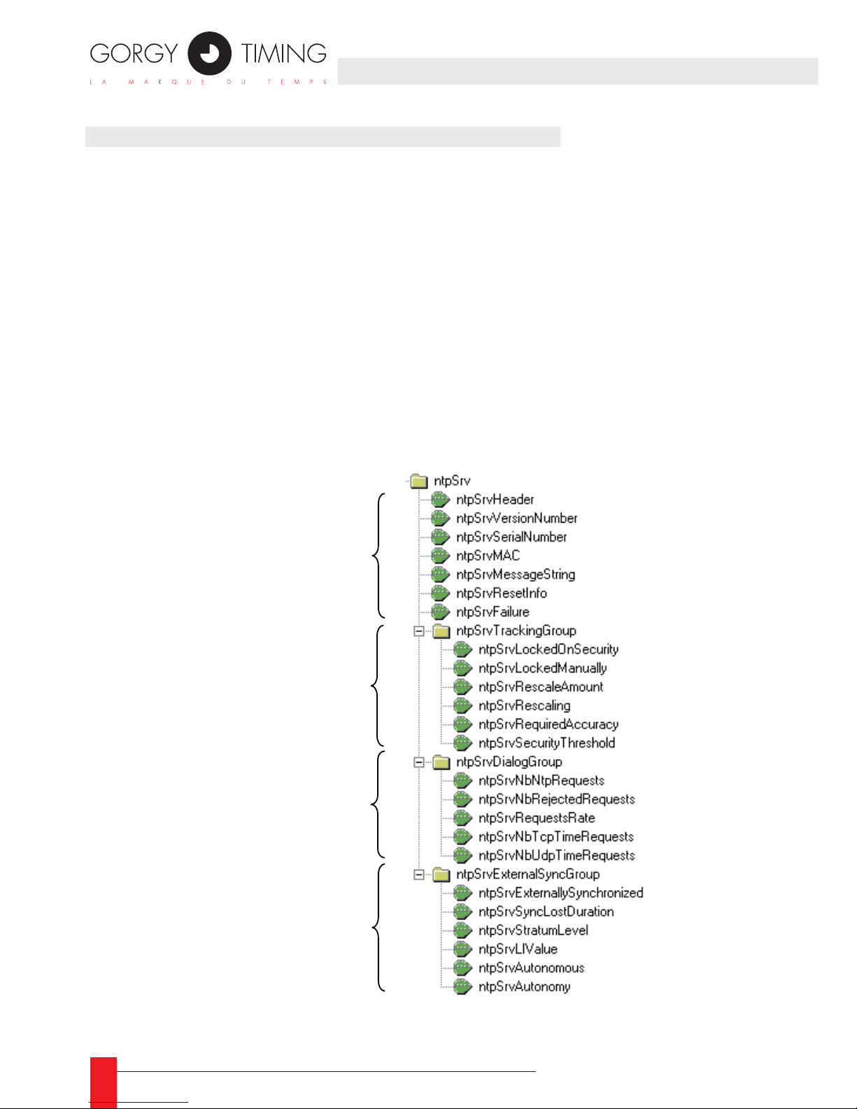
88
MDE-LEDI-NETWORK-IN-4065V1.0
5.2. SNMP INTERFACE FOR NTP SERVER CARD
The NTP server card provides its own a SNMP v1 interface for ne monitoring and diagnostic. Its private MIB is described in the le GtNtpServer.mib provided on the CDROM in the
directory English\LEDI Network IN\MIB.
Localization in the MIB:
iso(1).org(3).dod(6).internet(1).private(4).enterprises(1).gorgy(8955).software(1).ntpSrv(3)
5.2.1. Software information MIB for the NTP server outcard
General organization
This branch contains all the information related to the server software itself. Here is the
structure of this branch:
General information
Information related to the
hardware PPS tracking
algorithm
Information related to the
synchronization network dialog
Information related to the
external synchronization
Page 89

89
MDE-LEDI-NETWORK-IN-4065V1.0
GENERAL INFORMATION
ntpSrvHeader ►
Short description of the NTP server output card.
ntpVersionNumber ►
Version and release date of the NTP server rmware
ntpSrvSerialNumber ►
Serial number of the Ethernet interface (unique for each device)
ntpSrvMAC ►
Address of the Ethernet interface (MAC address)
ntpSrvMessageString ►
A text bound with each generated trap. It contains the text bound to the last gene-
rated trap.
ntpSrvResetInfo ►
A text that gives the reason of the last RESET.
ntpSrvFailure ►
true(1) if there is no time code and that the NTP output is deactivated
false(0) if the time code is present or the NTP server software can guarantee the
accuracy; NTP output is activated
TRACKING MODULE INFORMATION
ntpSrvLockedOnSecurity ►
true(1) if a time difference too important has been detected between the NTP
software clock and the time returned by the hardware, for security reasons, the NTP
server is currently locked
false(0) if no signicant time difference has been detected
ntpSrvLockedManually ►
true(1) if the software has been locked by a user
false(0) if the software is not locked by a user
ntpSrvRescaleAmount ►
A text that gives the amount of the difference between NTP software clock and
hardware time that leads to a security lock
unit: second
5. SNMP INTERFACE
ENGLISH
Page 90
90
MDE-LEDI-NETWORK-IN-4065V1.0
ntpSrvRescaling ►
true(1) if the NTP server software is currently rescaling on the hardware. During
rescaling stage, the NTP server don’t reply to clients
false(0) if no rescaling in progress
ntpSrvRequiredAccuracy ►
A text that gives the required accuracy for this NTP software (related to the time
provided by the hardware)
unit: seconds
NTP server outcard: this accuracy is xed to 0.24414 ms (4096-1 s)
ntpSrvSecurityThreshold ►
A text that gives the maximum accepted difference between software clock and
hardware time before locking the server
unit: seconds
NTP server outcard: this value is initialised to 65535.0 seconds
NETWORK DIALOG INFORMATION & STATISTICS
ntpSrvNbNtpRequests ►
Total number of received NTP requests (in fact all the requests received on port
123). When this counter reaches 32767, it reloops to 0.
ntpSrvNbRjectedRequests ►
Number of rejected NTP requests. A request can be rejected if it bad-formed, en-
cryption is invalid or the NTP server is locked. When this counter reaches 32767, it
reloops to 0.
ntpSrvRequestsRate ►
Shows an approximation of the average number of requests per seconds.
ntpSrvNbTcpTimeRequests ►
Total number of received TCP Time requests. When this counter reaches 32767, it
reloops to 0.
ntpSrvNbUdpTimeRequests ►
Total number of received UDP Time requests. When this counter reaches 32767, it
reloops to 0.
Page 91

91
MDE-LEDI-NETWORK-IN-4065V1.0
EXTERNAL SYNCHRONISATION INFORMATION
It gives information on an external time reference used by the hardware (for example
an antenna).
ntpSrvExternallySynchronized ►
notapplicable(2) if there is no information on external time reference
true(1) if the hardware is correctly synchronized on its external time reference
false(0) if the hardware is not synchronized on its external time reference (out of
radio coverture?)
ntpSrvSyncLostDuration ►
Number of seconds since beginning of synchronisation lose or duration of last synchronisation lose
ntpSrvStratumLevel ►
Current stratum level. This is the value returned to the NTP client.
This value can change when the synchronisation is lost depending on the policy
dened in the setup.
Moreover, the default value can be changed through the setup.
ntpSrvLIValue ►
Current LI value. This is the value returned to the NTP client.
This value can change when the synchronisation is lost depending on the policy
dened in the setup.
ntpSrvAutonomous ►
true(1) if the NTP software is using its own clock to deliver time through the NTP
false(0) if the NTP software is using time code from its synchronisation input
ntpSrvAutonomous ►
If ntpSrvAutonomous=false, give number of seconds that the server can works
without time code at its input
If ntpSrvAutonomous=true, give number of remaining seconds before stopping
synchronizing equipment through NTP
Other texts are possible (for example when there is no possible autonomy)
5. SNMP INTERFACE
ENGLISH
Page 92
92
MDE-LEDI-NETWORK-IN-4065V1.0
5.2.2. Description of the SNMP traps
# Related MIB variable Alarm meaning
8 ntpSrvAutonomy Warning: no time code. The time base has
less than 3 minutes of autonomy
7 ntpSrvFailure Failure: no more time code and the time base
has no more autonomy
6
5
ntpSrvRescaled
ntpSrvRescaling
NTP server software is rescaled or is resca-
ling on its PPS source
4 ntpSrvSecurityLock NTP server locked consequently to an abrupt
rescaling
3 ntpSrvUserLock NTP server locked by the user
1
2
ntpSrvSynchronized
ntpSrvUnSynchronized
The hardware is synchronized or not on its
time reference
Page 93
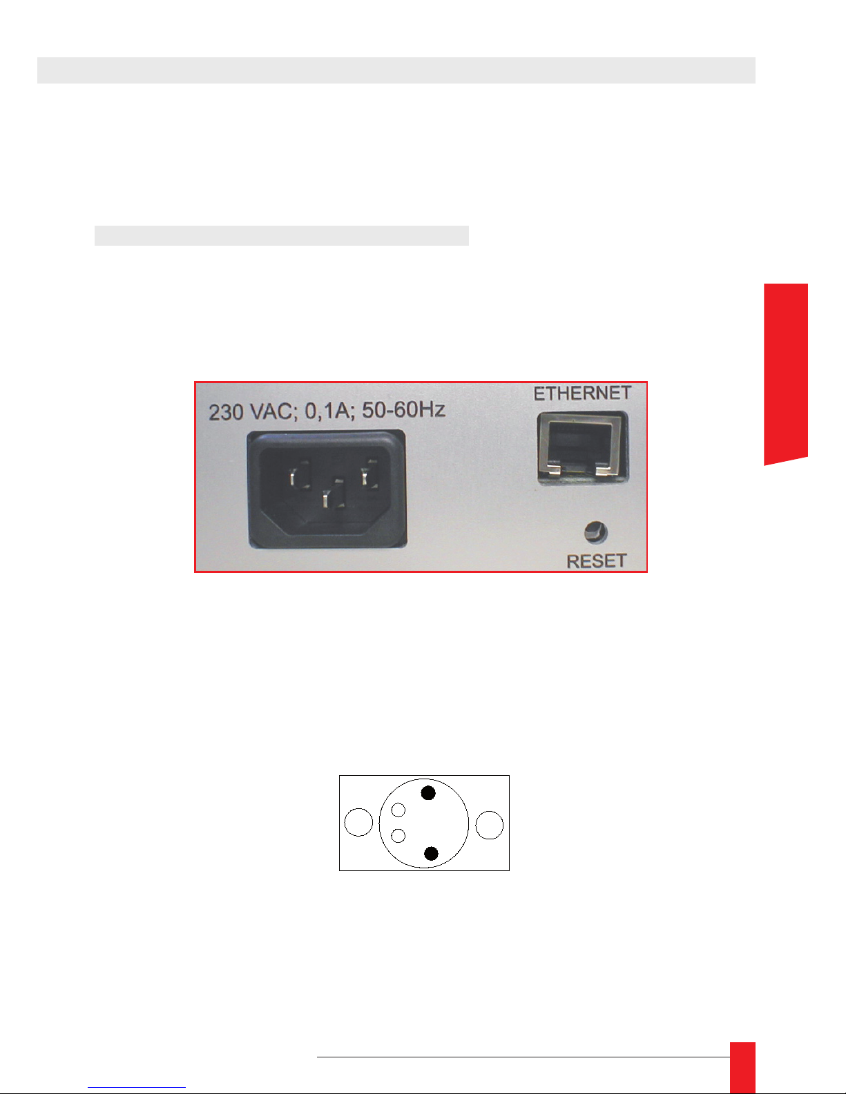
93
MDE-LEDI-NETWORK-IN-4065V1.0
This appendix contains a description of the different connectors of the LEDI Network
IN. All the plugs are localized on the backside of the product.
1. CONNECTION FOR ALL PRODUCTS
1.1. 230V and 115V AC product (type ‘0’)
The backside of the product has a standard power supply plug, the Ethernet RJ45 plug
and a RESET button as shown below:
1.2. 18/72V DC product (type ‘9’)
The Ethernet connector and the RESET button are the same.
Only the power supply plug is different.
APPENDIX A – CONNECTIONS
0V
+V DC
ENGLISH
Page 94
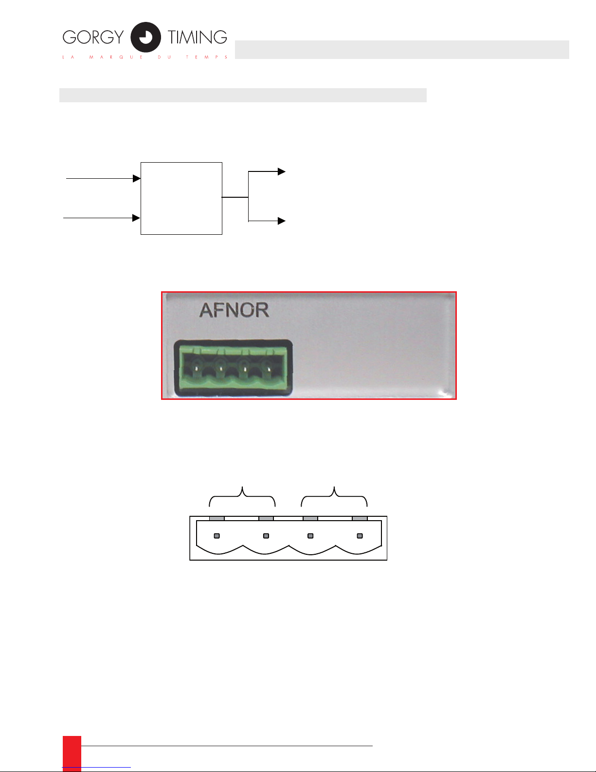
94
MDE-LEDI-NETWORK-IN-4065V1.0
2. DUAL AFNOR/IRIG-B NFS87500 OUTPUT (‘B’ TYPE)
This card has its output on a single 4 points plug. The AFNOR code is available twice on
this output. Here is a schematic overview of the AFNOR/IRIG-B output card:
Time code
Amplitude
Modulator
The output connector is localized on the back side of the rack and is shown below:
Here is the pin-out of the connector (the same signal is generated on outputs ½ and ¾) :
Output 2
Output 1
1 2 3 4
Page 95
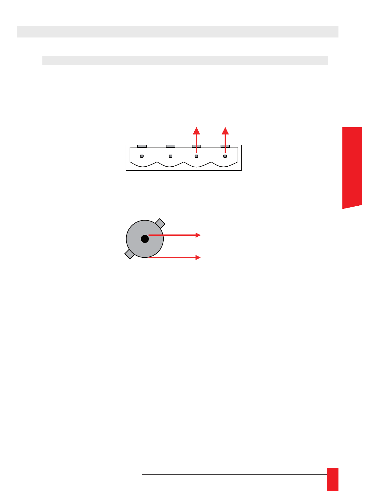
95
MDE-LEDI-NETWORK-IN-4065V1.0
APPENDIX A – CONNECTIONS
3. DUAL AFNOR/IRIG-B NFS87500 DCLS RS422 AND TTL OUTPUT
(‘T’ TYPE)
This card has its outputs on a 4 points plug and a BNC connector. The RS422 AFNOR code
is available on the 4 points output :
The BNC connector provides TTL signal :
Tx/Rx +
1 2 3 4
Tx/Rx -
Tx
GND
ENGLISH
Page 96
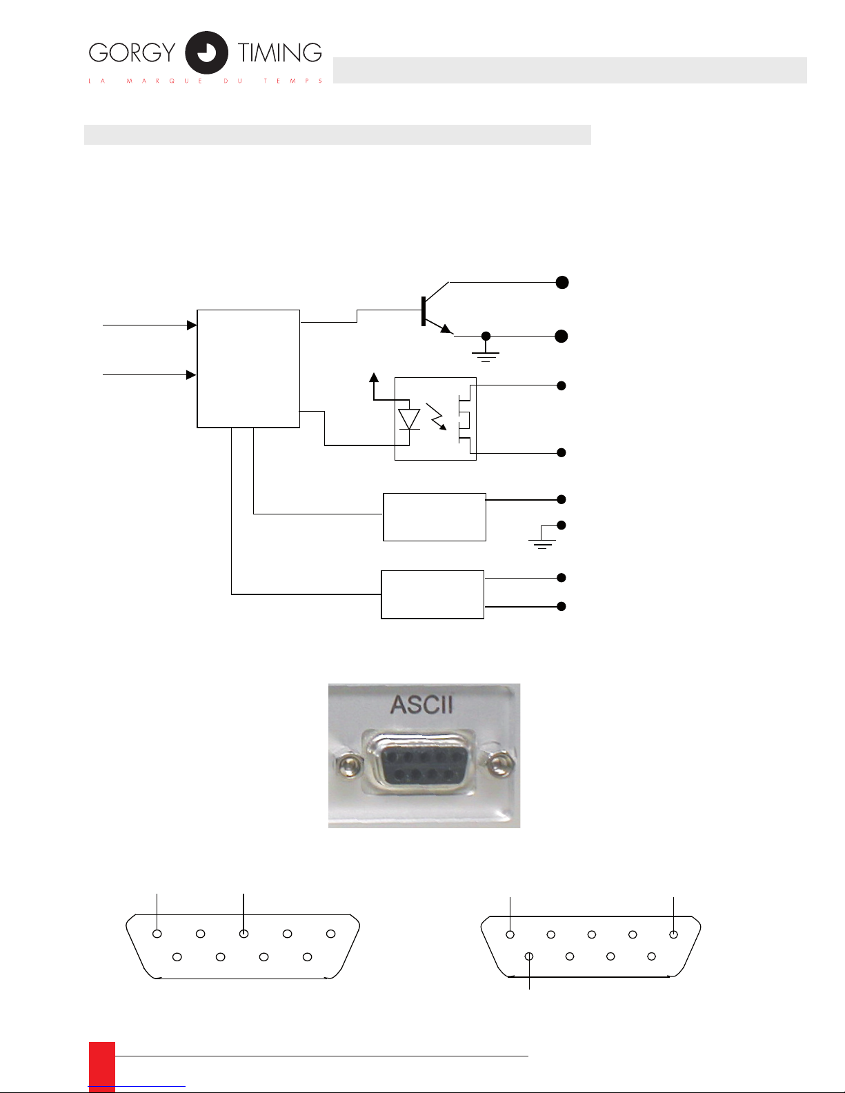
96
MDE-LEDI-NETWORK-IN-4065V1.0
4. RS232 AND 485/422 ASCII+TOP (‘A’ AND ‘R’ TYPE)
The ASCII+TOP card has a 4 points plug and a DB9 connector. The 4 points plug is used
to output the TOP through static relays and the DB9 plug is used to output time frame using
RS-232 levels.
Here is a schematic overview of the ASCII+TOP output:
The ASCII DB9 connector is localized on the backside of the rack and is shown below.
Connector pin-out for RS232 : Connector pin-out for RS485 and RS422 :
The pulse (TOP) output is described below.
TOP
Time code
Driver
Open collector output
VCC
Static relay output
RS-232 line
driver
RS-485 line
driver
TXD
TX+
TX-
RS-232 output
RS-485 output
GND
TXD
GND
TX+
TX-
Page 97
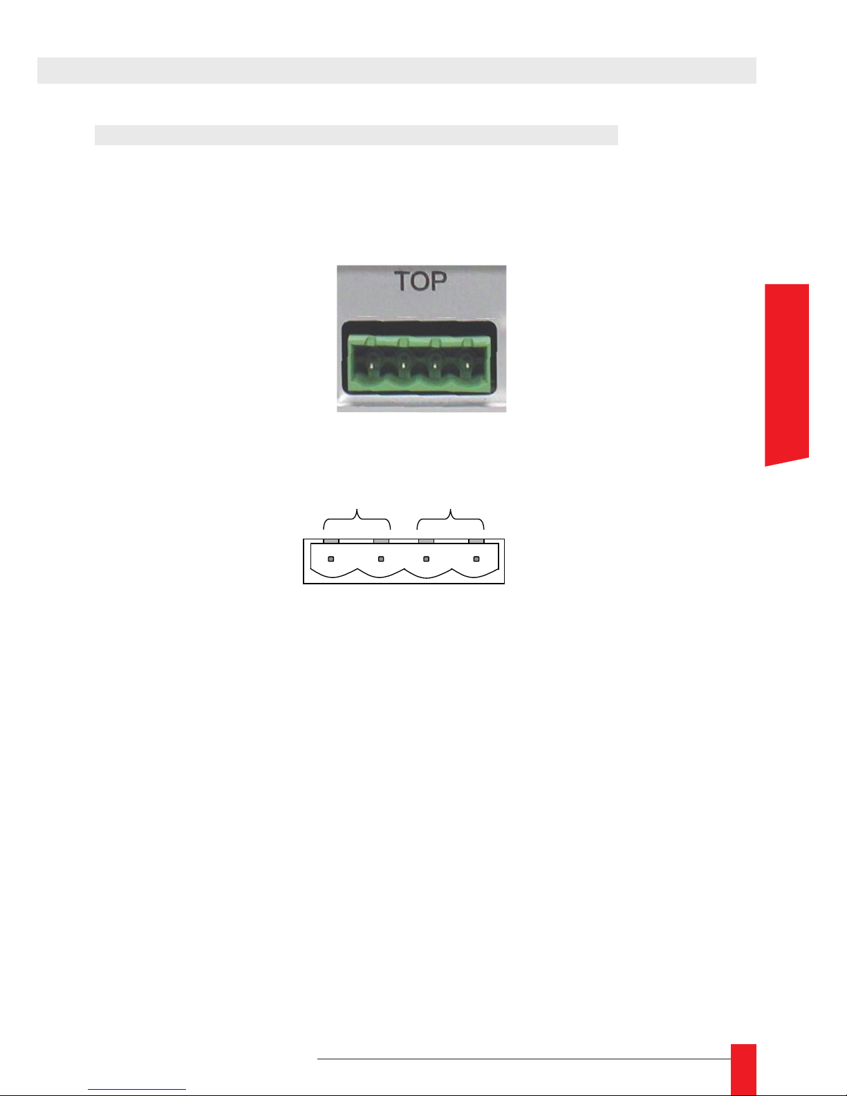
97
MDE-LEDI-NETWORK-IN-4065V1.0
5. TOP / ALARM OUTPUT (‘A’, ‘R’ TYPE AND ‘G’ TYPE)
5.1. Pin-out
The 4 points plug on the ASCII and ALARM cards can provide a congurable time TOP
or synchro/power alarm TOP.
The 4 points plug has the following pin-out:
Static Relay Outputs 1 and 2 : ►
Pin 1, Pin 2 ► : without polarity
Max. switching voltage ► : 350 V AC/DC
Max. switching current ► : 130 mA
Open Collector output ►
Pin 4 ► : Gnd Pin 3 : +
Max. voltage ► : 45 V
Max. curren ► t : 30 mA
APPENDIX A – CONNECTIONS
open collector output
static relay output 1
1 2 3 4
ENGLISH
Page 98
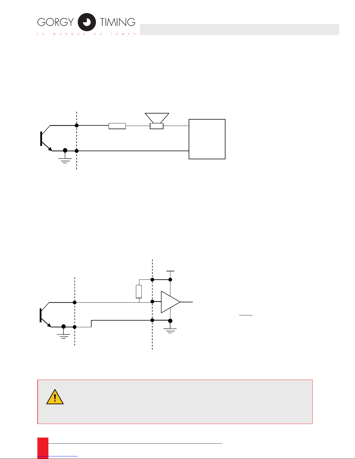
98
MDE-LEDI-NETWORK-IN-4065V1.0
Here are some examples of how to use this output :
5.2. Examples of how to use the open collector output (pins 3-4)
General case :
You need to add R if the load (LED, loudspeaker,…) does not accept the VDC ►
voltage.
To avoid the transistor destruction, limit the input current to 30 mA (i = Vdc / R < ►
30mA).
TTL input command :
R
External
DC
+
-
WARNING :
VDC max = 45 Volts
3
4
loudspeaker
3
4
R
VDC
TTL input
If VDC = 5 Volts :
Ω== 167
0.03
5
Rmin
so take
Ω≥ 180R
WARNING : The open collector output is not compatible with an
extern power supply with a + pin connected to earth (telecom 48
Volts)..
Page 99
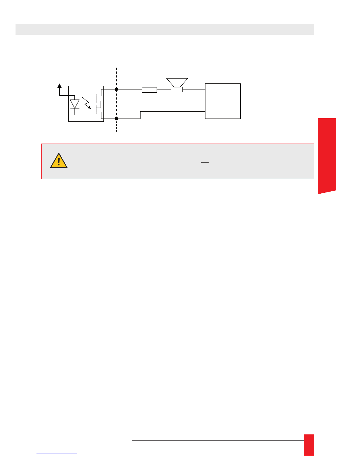
99
MDE-LEDI-NETWORK-IN-4065V1.0
5.3. Example of how to use the static relay output (pins 1-2)
R
External
DC or AC
+
-
WARNING :
V max = 60 Volts
VCC
1
2
loudspeaker
pulse
WARNING : You must ensure that
mA
R
V
i 130<=
APPENDIX A – CONNECTIONS
ENGLISH
Page 100

100
MDE-LEDI-NETWORK-IN-4065V1.0
This appendix contains a description of the time code used for the different kind of
outputs.
1. ‘A’ AND ‘R’ TYPE CARDS (ASCII+TOP OUTPUT)
The default conguration is shown below:
The PPS is generated every 30 seconds and is 1 second long; ►
The ASCII frame is generated at the same time than the PPS. This frame is a 23 ►
characters frame with following format:
STX D A Y D D / M M / Y Y H H : M M : S S CR
Here is a description of the different elds of this frame:
Field Size Value/Meaning
STX 1 A single byte which value is 2 – mark the beginning of the frame.
DAY 3
The day in the week in a human-readable way (MON for Monday, TUE
for Tuesday, WED for Wednesday, THU for Thursday, FRI for Friday,
SAT for Saturday, SUN for Sunday)
DD 2 Day in the month on two characters ASCII (01-31)
MM 2 Month in the year on two characters ASCII (01-12)
YY 2 Year on two characters ASCII (00 for 2000 – 99 for 2099)
HH 2 Hours on two characters ASCII (00 to 23)
MM 2 Minutes on two characters ASCII (00 to 59)
SS 2 econds on two characters ASCII (00 to 59)
CR 1 A single byte which value is 13decimal – mark the end of the frame
 Loading...