

Gorenje G34AX1 - 249046, G760AX1 - 236632 Instruction Manual
Instructions for the installation
and advice for the maintenance
G760AX1 - 236632
G34AX1 - 249046
Instructions Manual
G760AX1 - 236632
G34AX1 - 249046
COD. 04037KESTGOA (04037GB) - 14.07.2010

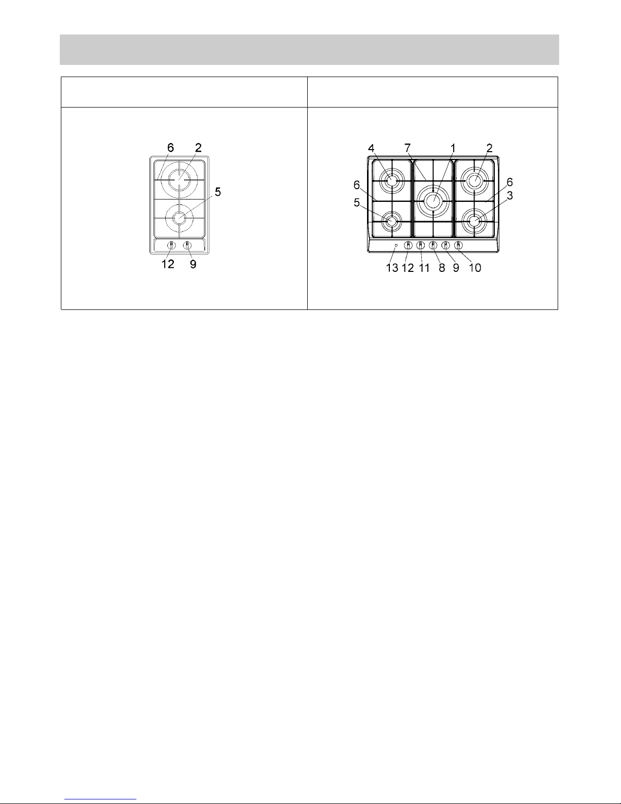
DESCRIPTION OF THE HOT PLATES
1 Ultra rapid gas burner of 3100 W
2 Rapid gas burner of 2800 ÷ 3000 W
3 Semirapid gas burner right front of 1400 W
4 Semirapid gas burner left back of 1750 W
5 Auxiliary gas burner of 1000 W
6 Enamelled steel pan support 2F
7 Central enamelled steel pan support
8 Burner n° 1 control knob
9 Burner n° 2 control knob
10 Burner n° 3 control knob
11 Burner n° 4 control knob
12 Burner n° 5 control knob
13 Electric ignition button
Attention: this appliance has been manufactured for domestic use only and it employment by
private person.
MODEL: G760AX1 - 236632
2
MODEL: G34AX1 - 249046

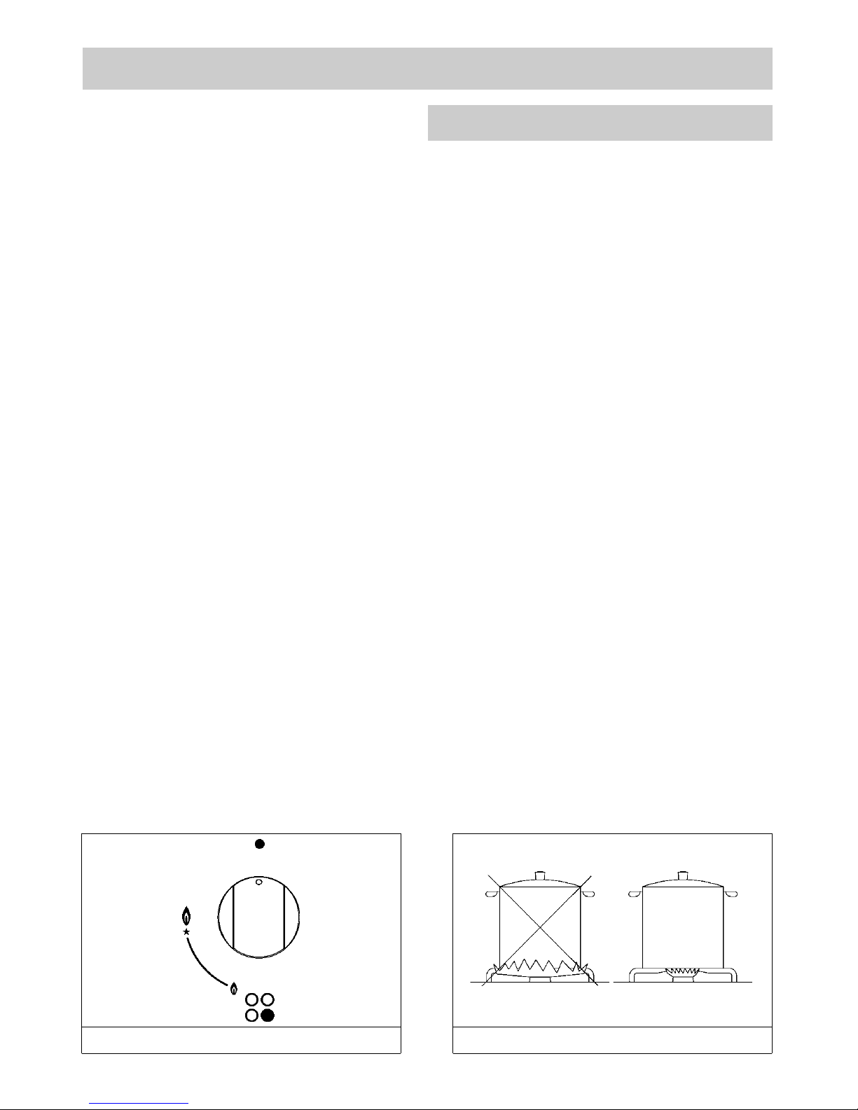
1) BURNERS
A diagram is screen-printed above each knob on
the front panel. This diagram indicates to which
burner the knob in question corresponds. After
having opened the gas mains or gas bottle tap, light
the burners as described below:
- manual ignition
Push and turn the knob corresponding to the
required burner in an anticlockwise direction until it
reaches the full on position (large flame fig. 1), then
place a lighted match near the burner.
- Electrical ignition
Push and turn the knob corresponding to the
required burner in an anticlockwise direction until it
reaches the full on position (large flame fig. 1), then
depress and release the ignition button.
- Automatic electrical ignition
Push and turn the knob corresponding to the
required burner in an anticlockwise direction until it
reaches the full on position (large flame fig. 1), then
depress the knob.
- Lighting burners equipped with flame failure
device
The knobs of burners equipped with flame failure
device must be turned in an anticlockwise direction
until they reach the full on position (large flame fig. 1)
and come to a stop. Now depress the knob in
question and repeat the previously indicated
operations.
Keep the knob depressed for about 10 seconds
once the burner has ignited.
HOW TO USE THE BURNERS
Bear in mind the following indications in order to
achieve maximum efficiency with the least possible
gas consumption:
- use adequate pans for each burner (consult the
following table and fig. 2).
- When the pan comes to the boil, set the knob to
the reduced rate position (small flame fig. 1).
- Always place a lid on the pans.
- Use only pan with a flat bottom.
WARNINGS:
- burners with flame failure device may only be
ignited when the relative knob has been set
to the Full on position (large flame fig. 1).
- Matches can be used to ignite the burners in
a blackout.
- Never leave the appliance unattended when
the burners are being used. Make sure there
are no chil dren in the near vic inity.
Particularly make sure that the pan handles
are correctly positioned and keep a chek on
foods requiring oil and grease to cook since
these products can easily catch fire.
- Never use aerosols near the appliance when
it is operating.
- If the built-in hot plate has a lid, any spilt food
should be immediately removed from this
before it is opened. If the appliance has a
glass lid, this could shatter when the hot
plate becomes hot. Always switch off all the
burners before closing the lid.
- The machine must not be used by people
(including children) with impaired mental or
physical capacities, or without experience of
using electrical devices, unless supervised
or instructed by an expert adult responsible
for their care and safety. Children should not
be allowed to play with the equipment.
- Containers wider than the unit are not
recommended.
USE
FIG. 1 FIG. 2
3
Burners Power ratings
Pan Ø in cm
Ultra rapid 3100 24 ÷ 26
Rapid 2800 ÷ 3000 20 ÷ 22
Semirapid right front 1400 16 ÷ 18
Semirapid left back 1750 16 ÷ 18
Auxiliar 1000 10 ÷ 14
USE
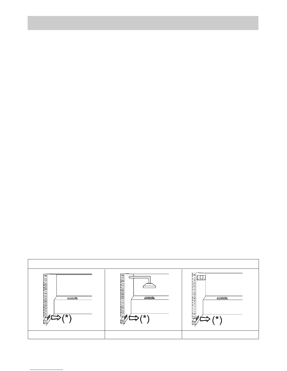
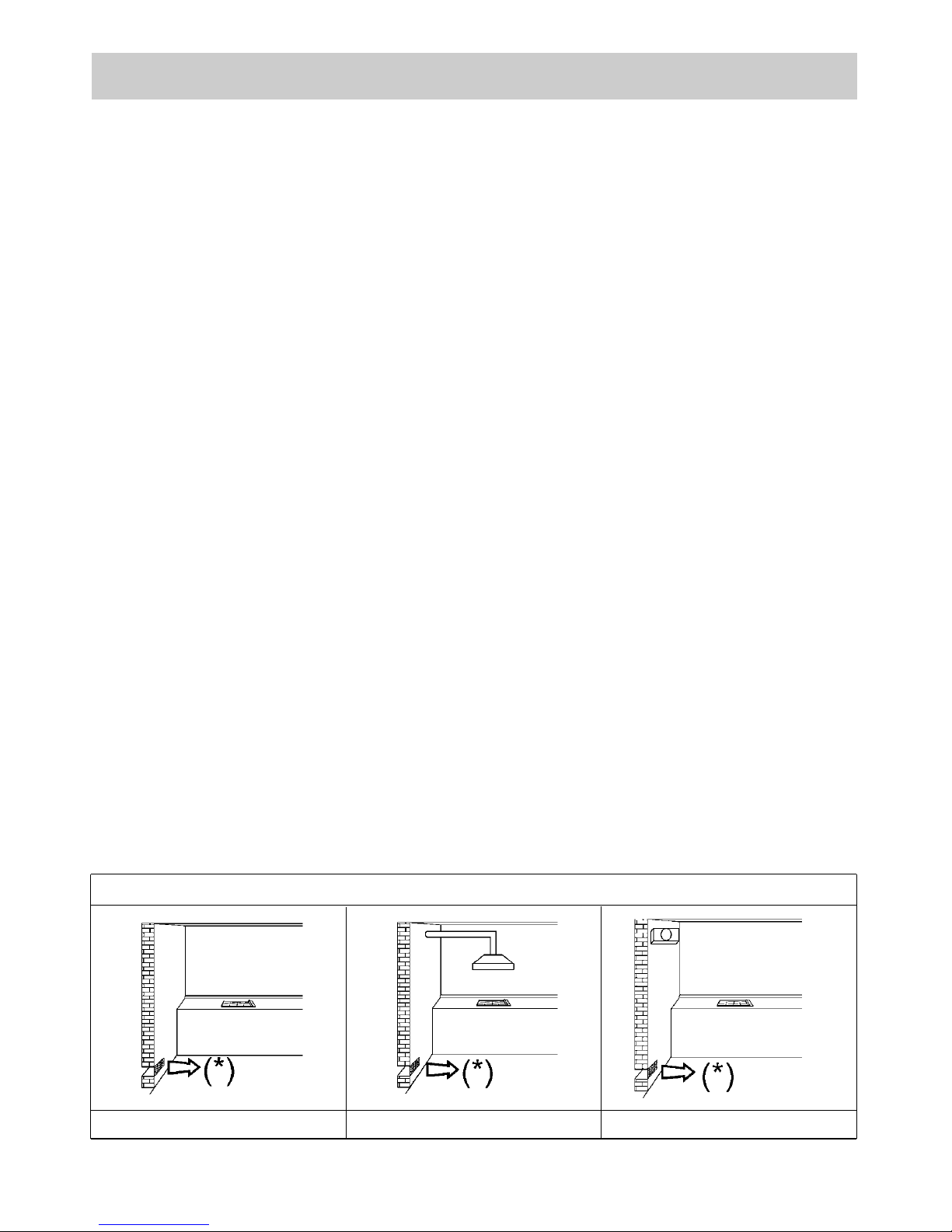
Notes:
use of a gas cooking appliance produces heat and moisture in the room in which it is installed.
The room must therefore be well ventilated by keeping the natural air vents clear (fig. 3) and by
activating the mechanical aeration device (suction hood or electric fan fig. 4 and fig. 5).
Intensive and lengthy use of the appliance may require additional ventilation. This can be
achieved by opening a window or by increasing the power of the mechanical exhausting system if
installed.
FIG. 3 FIG. 4 FIG. 5
(*) AIR INLET: SEE INSTALLATION CHAPTER (PARAGRAPHS 5 AND 6)
4
CLEANING
IMPORTANT:
always disconnect the appliance from the gas
and electricity mains before carrying out any
cleaning operation.
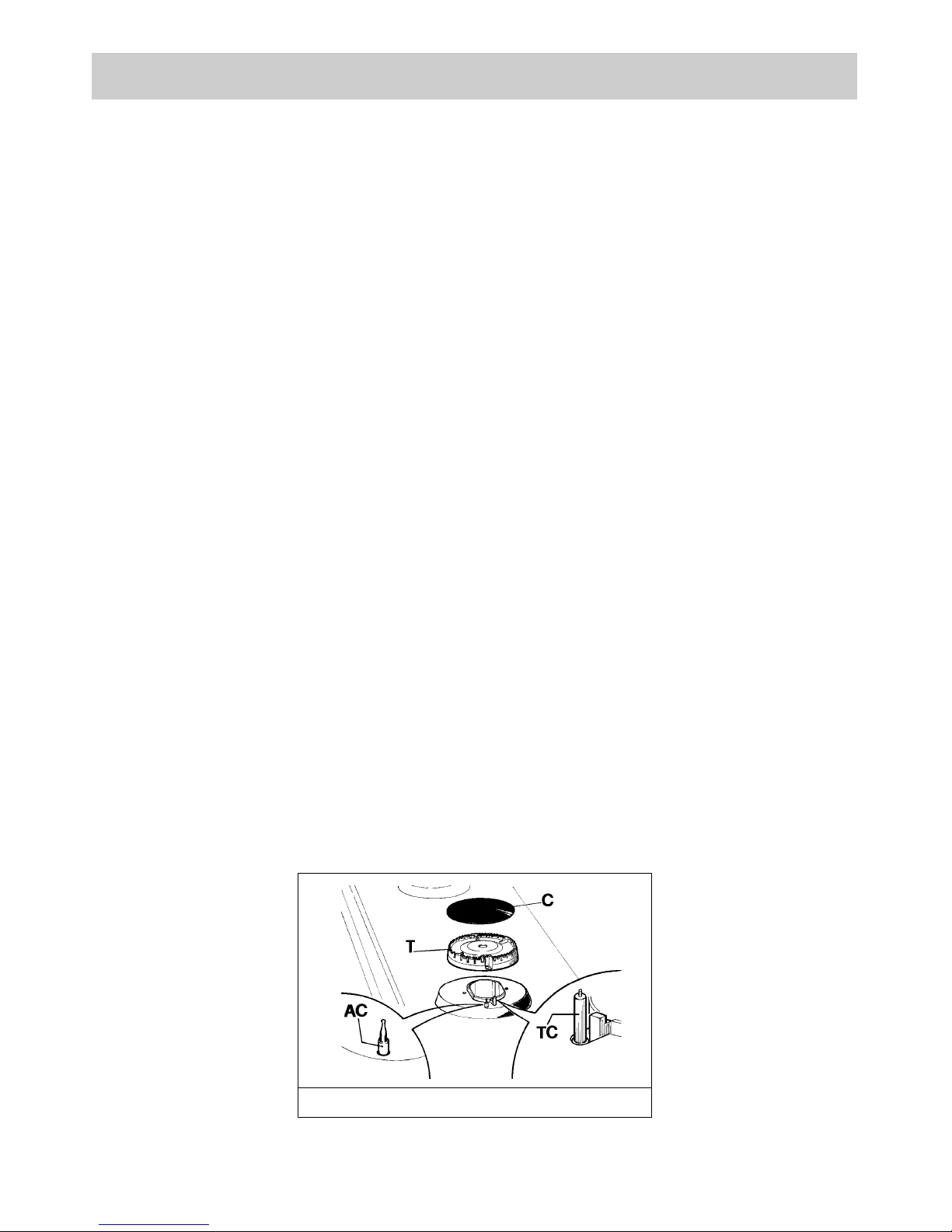
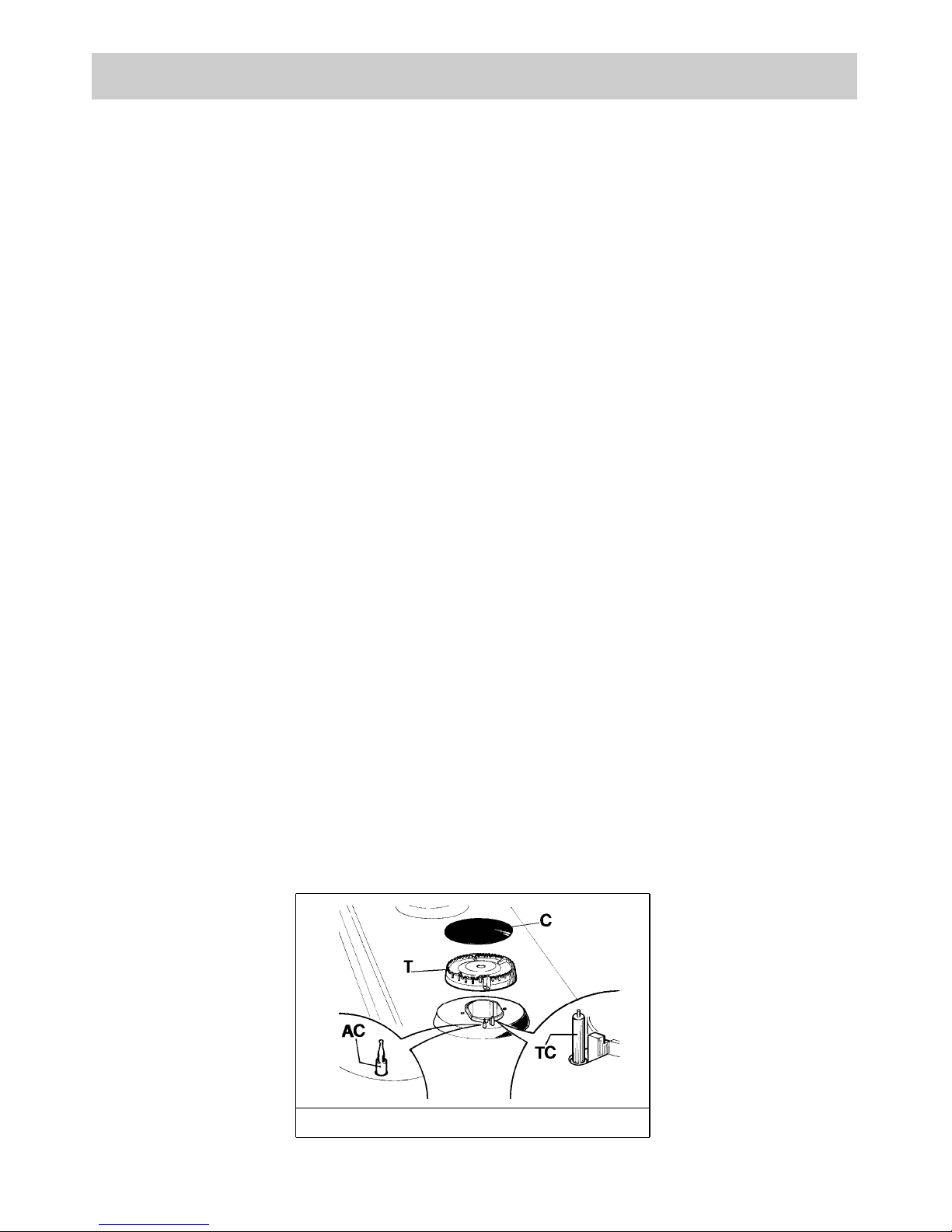
2) HOT PLATE
Periodically wash the hot plate, the enamelled stell
pan support, the enamelled burner caps “C” and
the burner heads “T” (see fig. 6) with lukewarm
soapy water. Following this, all parts should be
thoroughly rinsed and dried. Never wash them
while they are still warm and never use abrasive
powders. Do not allow vinegar, coffee, milk, salted
water, lemon or tomato juice from remaining in
contact with the enamelled surfaces for long
periods of time.
WARNINGS:
comply with the following instructions, before
remounting the parts:
- check that burner head slots “T” (fig. 6) have
not become clogged by foreign bodies.
- Check that enamelled burner cap “C” (fig. 6)
have correctly positioned on the burner head.
It must be steady.
- The exact position of the pan support is
established by the rounded corners, which
should be set towards the side edge of the
hot plate.
- Do not force the taps if they are difficult open
or close. Contact the technical assistance
service for repairs.
- Don’ t use steam jets for the equipment
cleaning.
FIG. 6
5
INSTALLATION
TECHNICAL INFORMATION
FOR THE INSTALLER
Installation, adjustments of controls and
maintenance must only be carried out by a
qualified engineer.
Incorrect installation may cause damage to
persons, animals or property for which the
Manufacturer shall not be considered
responsible.
During the life of the system, the automatic
safety or regulating devices on the appliance
may only be modified by the manufacturer or by
his duly authorized dealer.
3) INSTALLING THE HOT PLATE
Check that the appliance is in a good condition after
having removed the outer packaging and internal
wrappings from around the various loose parts. In
case of doubt, do not use the appliance and contact
qualified personnel.
Never leave the packaging materials
(cardboard, bags, polystyrene foam, nails, etc.)
within children’s reach since they could become
potential sources of danger.
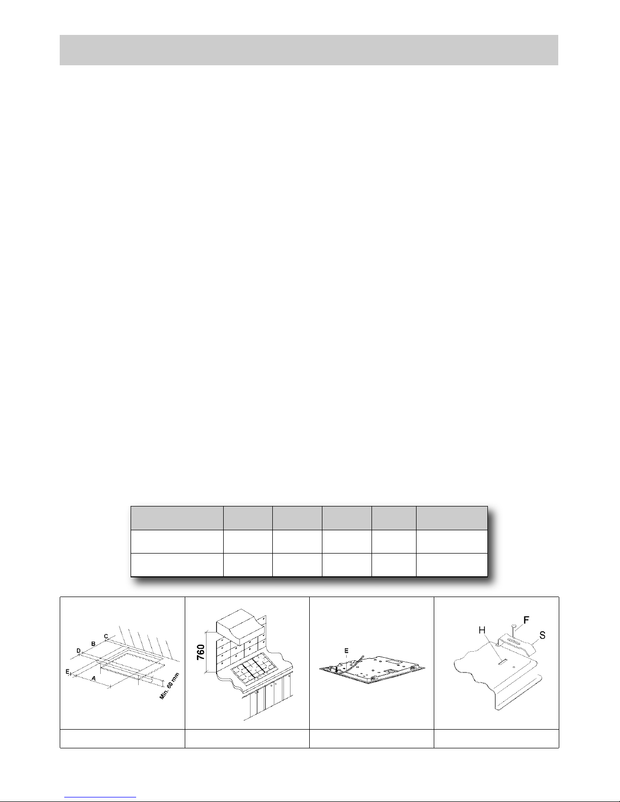
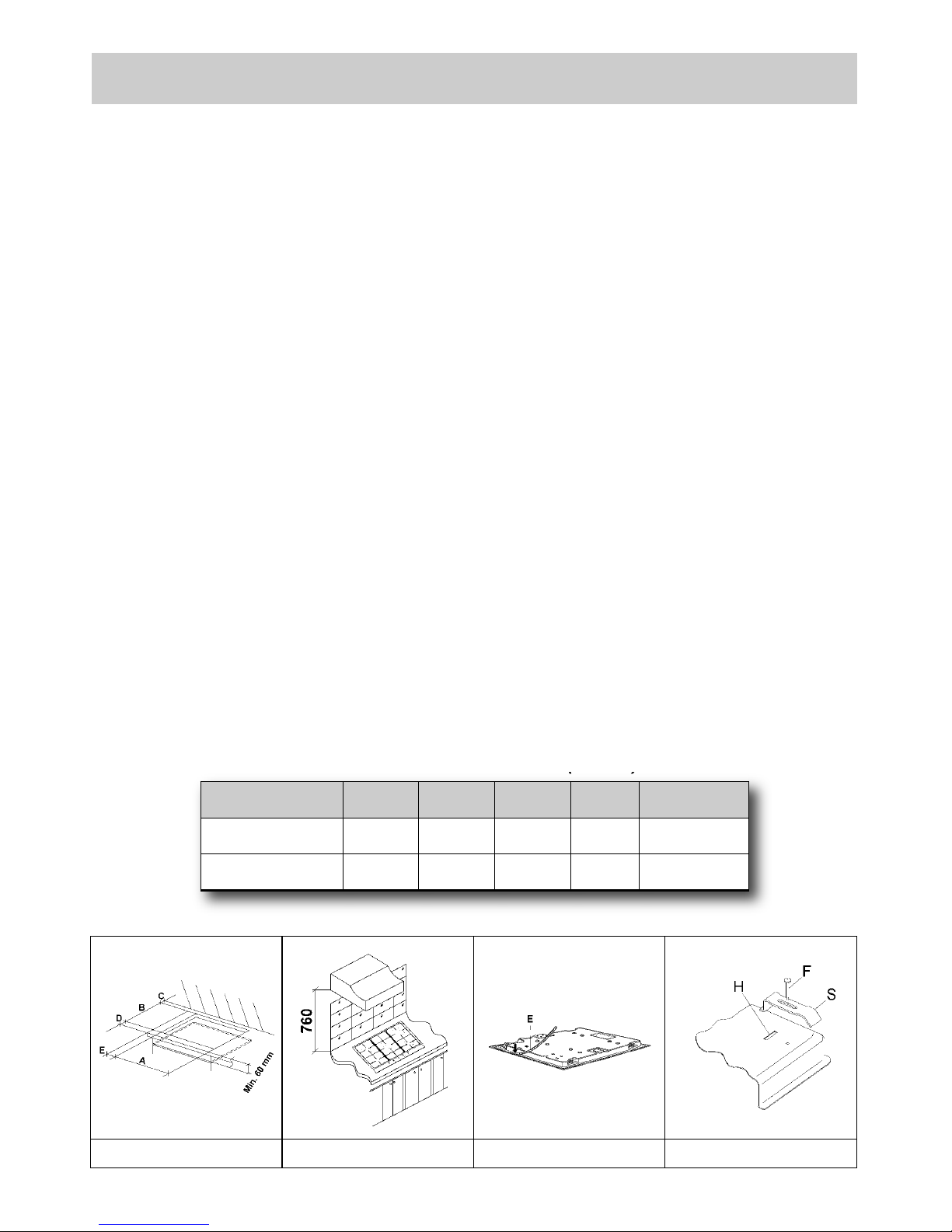
The measurements of the opening made in the top
of the modular cabinet and into which the hot plate
will be installed are indicated in either fig. 7. Always
comply with the measurements given for the hole
into which the appliance will be recessed (see
fig. 7 and 8).
The appliance belongs to class 3 and is
therefore subject to all the provisions
established by the provisions governing such
appliances.
4) FIXING THE HOT PLATE
The hot plate has a special seal which prevents
liquid from getting into the cabinet. Strictly comply
with the following instructions in order to correctly
apply this seal:
- detach the seals from their backing, checking that
the transparent protection still adheres to the seal
itself.
- Overturn the hot plate and correctly position seal
“E” (fig. 9) under the edge of the hot plate itself, so
that the outer side of the seal perfectly matches
the outer edge of the hot plate. The ends of the
strips must fit together without overlapping.
- Evenly and securely fix the seal to the hot plate,
pressing into place with the fingers and remove
the strip of protective paper from the seal and set
the plate into the hole made in the cabinet.
- Fix the hob with the proper brackets “S” and fit the
prominent part into the porthole “H” on the bottom;
turn the screw “F” until the bracket “S” stick on the
top (fig. 10).
- In order to avoid accidental touch with the
overheating bottom of the hob, during the working,
is necessary to put a wooden insert, fixed by
screws, at a minimum distance of 60 mm from the
top (see fig. 7).
FIG. 7 FIG. 8 FIG. 9
FIG. 10
COMPLY WITH THE DIMENSIONS (mm)
6
A B C D E
2F (30) 282 482 59 59 100 min.
5F (70) 553 473 63.5 63.5 175 min.

IM PO RTANT I NS TA LL ATIO N
SP EC IF IC AT IO NS
The installer should note that the appliance that side
walls should be no higher than the hot plate itself.
Furthermore, the rear wall, the surfaces surrounding
and adjacent to the appliance must be able to withstand
an overtemperature of 65 K.
The adhesive used to stick the plastic laminate to the
cabinet must be able to withstand a temperature of not
less than 150 °C otherwise the laminate could come
unstuck.
The appliance must be installed in compliance with the
provisions in force.
This appliance is not connected to a device able to
dispose of the combustion fumes. It must therefore be
connected in compliance with the above mentioned
installation standards. Particular care should be paid to
the following provisions governing ventilation and
aeration.
5) ROOM VENTILATION
It is essential to ensure that the room in which the
appliance is installed is permanently ventilated in order
to allow the appliance itself to operate correctly. the
necessary amount of air is that required for regular gas
combustion and ventilation of the relative room, the
volume of which must not be less than 20 m3. Air must
naturally flow through permanent openings in the walls
of the room in question. These openings must vent the
fumes outdoors and their section must be at least
100 cm2 (see fig. 3). Construction of the openings must
ensure that the openings themselves may never be
blocked. Indirect ventilation by air drawn from an
adjacent room is also permitted, in strict compliance
with the provisions in force.
CAUTION: if the burners of the cooking top are
without safety thermocouple, the ventilation outlet
must have a minimum 200 cm² section.
6) LOCATION AND AERATION
Gas cooking appliances must always dispose of their
combustion fumes through hoods. These must be
connected to flues, chimneys or straight outside. If it is
not possible to install a hood, an electric fan can be
installed on a window or on a wall facing outside (see
fig. 4). This must be activated at the same time as the
appliance (see fig. 5), so long as the specifications in the
provisions in force are strictly complied with.
7) GAS CONNECTION
Before connecting the appliance, check that the values
on the data label affixed to the underside of the hot plate
correspond to those of the gas and electricity mains in
the home.
A label on the appliance indicates the regulating
conditions: type of gas and working pressure. Gas
connection must comply with the pertinent standards
and provisions in force.
When gas is supplied through ducts, the appliance must
be connected to the gas supply system:
o with a rigid steel pipe. The joints of this pipe must consist
of threaded fittings conforming to the standards.
o With copper pipe. The joints of this pipe must consist of
unions with mechanical seals.
o With seamless flexible stainless steel pipe. The length of
this pipe must be 2 meters at most and the seals must
comply with the standards.
When the gas is supplied by a bottle, the appliance must
be fuelled by a pressure governor conforming to the
provisions in force and must be connected:
o with a copper pipe. The joints of this pipe must consist of
unions with mechanical seals.
o With seamless flexible stainless steel pipe. The length of
this pipe must be 2 meters at most and the seals must
comply with the standards. It is advisable to apply the
special adapter to the flexible pipe. This is easily available
from the shops and facilitates connection with the hose
nipple of the pressure governor on the bottle.
o With rubber hose pipe in compliance with standards. The
diameter of this hose pipe must be 8 mm and its length
must be no less than 400 mm and no more than
1500 mm. It must be firmly fixed to the hose nipple by
means of the safety clamp specified by standards.
At the connection end, verify the gasproof using a soap solution,
never a flame.
WARNINGS:
remember that the gas inlet union on the appliance
is a 1/2" gas cylindric male type in compliance with
ISO 228-1 standards.
Installation of stainless steel pipe and rubber hose
pipe must ensure that it is never able to touch
mobile parts of the built-in cabinet (eg. drawers).
Furthermore, it must not pass through
compartments that could be used for storage
purposes.
When using a rubber hose pipe, it is essential to
comply with the following instructions:
- no part of the pipe must be able to touch parts
the temperature of which exceeds 65 K.
- The pipe must not be pulled or twisted, throttled
or tughtly bent.
- It must not come into contact with sharp edges
or corners.
- It must be easy to inspect the entire pipe length
in order to check its state of wear.
- The pipe must be replaced within the date
stamped on the pipe itself.
- The appliance complies with the provisions of
the following CEE Directives:
90/396 + 93/68 regarding gas safety.
INSTALLATION
7
8) ELECTRICAL CONNECTION
The electrical connections of the appliance
must be carried out in compliance with the
provisions and standards in force.
Before connecting the appliance, check that:
- the electrical capacity of the mains supply and
current sockets suit the maximum power rating of
the appliance (consult the data label applied to the
underside of the hot plate).
- The socket or system has an efficient earth
connection in compliance with the provisions and
standards in force. The manufacturer declines all
responsibility for failing to comply with these
provisions.
When the appliance is connected to the
electricity main by a socket:
- fit a standard plug suited to the load indicated on
the data label to the cable.
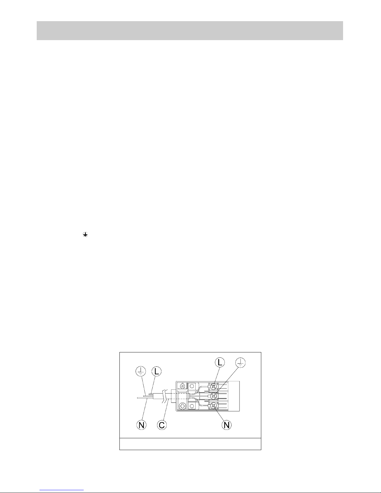
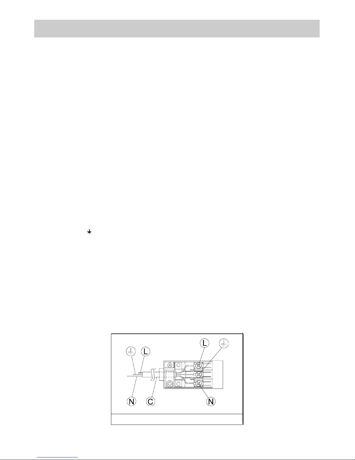
- Fit the wires following figure n. 11, taking care of
respecting the following correspondences:
letter L (live) = brown wire;
letter N (neutral) = blue wire;
earth symbol = green - yellow wire
- The power supply cable must be positioned so
that no part of it is able to reach an
overtemperature of 75 K.
- Never use reductions, adapters of shunts for
connection since these could create false contacts
and lead to dangerous overheating.
- The outlet must be accessible after the built-in.
When the appliance is connected straight to the
electricity main:
- install an omnipolar circuit-breaker between the
appliance and the electricity main. This circuitbreaker should be sized according to the load
rating of the appliance and possess a minimum 3
mm gap between its contacts.
- Remember that the earth wire must not be
interrupted by the circuit-breaker.
- Alternatively, the electrical connection may also be
protected by a high sensitivity differential circuitbreaker.
You are strongly advised to fix the relative yellowgreen earth wire to an efficient earthing system.
WARNINGS:
all our appliances are designed a nd
manufactured in compliance with European
standards EN 60 335-1, EN 60 335-2-6 and
EN 60 335-2-102 plus the relative amendments.
The appliance complies with the provisions of
the following CEE Directives:
- CEE 2004/108/CE regarding to electromagnetic
compatibility.
- CEE 2006/95 regarding electrical safety.
INSTALLATION
FIG. 11
8
ADJUSTMENTS
Always disconnect the appliance from the
electricity main before making any adjustments.
All seals must be replaced by the technician at
the end of any adjustments or regulations.
Our burners do not require primary air
adjustment.
9) TAPS
“Reduced rate” adjustment
- Switch on the burner and turn the relative knob to
the “Reduced rate” position (small flame fig. 1).
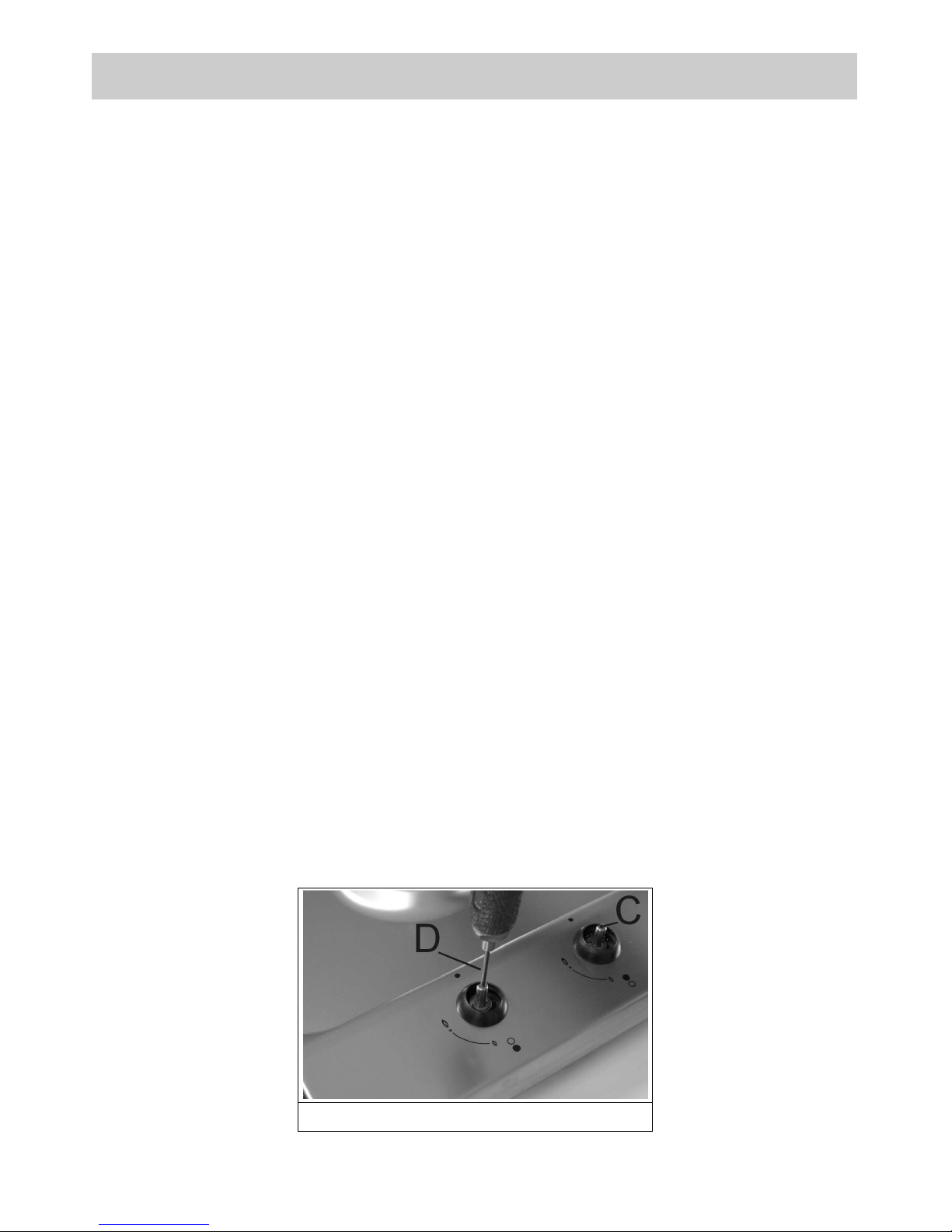
- Remove knob (fig. 12) of the tap, which is simply
pressed on to its rod.
- Insert a small screwdriver “D” into hole “C” (fig. 12)
and turn the throttle screw to the right or left until
the burner flame has been adequately regulated to
the “Reduced rate” position.
Check that the flame does not go out when the
knob is sharply switched from the “Full on” to the
“Reduced rate” position.
It is understood that only burners operating
with G20 gas should be subjected to the above
mentioned adjustments. The screw must be
fully locked when the burners operate with G30
or G31 gas (turn clockwise).
FIG. 12
9
10
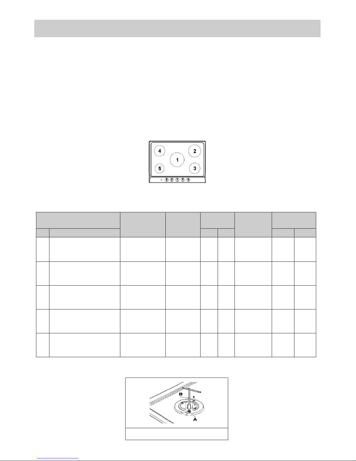
10) REPLACING THE INJECTORS
The burners can be adapted to different types of
gas by mounting injectors suited to the type of gas
in question. To do this, first remove the burner tops
using a wrench “B”. Now unscrew injector “A” (see
fig. 13) and fit a injector corresponding to the
utilized type of gas in its place.
It is advisable to strongly tighten the injector in
place.
After the injectors have been replaced, the
burners must be regulated as explained in
paragraphs 9. The technician must reset any
seals on the regulating or pre-regulating devices.
The envelope with the injectors and the labels can
be included in the kit, or at disposal to the
authorized customer Service Centre.
For the sake of convenience, the nominal rate table
also lists the heat inputs of the burners, the
diameter of the injectors and the working pressures
of the various types of gas.
BURNER ARRANGEMENT ON THE HOT PLATE
CONVERSIONS
TABLE
FIG. 13
BURNERS
GAS
NORMAL
PRESSURE
mbar
NORMAL
RATE
INJECTOR
DIAMETER
1/100 mm
NOMINAL HEAT
INPUT (W)
N°
DESCRIPTION
g/h l/h Min. Max.
1
ULTRA RAPID
G30 - BUTANE
G31 - PROPANE
G20 - NATURAL
28 - 30
37
20
225
221
295
90
90
121 Y
1400
1400
1400
3100
3100
3100
2
RAPID
G30 - BUTANE
G31 - PROPANE
G20 - NATURAL
28 - 30
37
20
204
200
267
83
83
117 S
800
800
800
2800
2800
2800
3
SEMIRAPID
RIGHT FRONT
G30 - BUTANE
G31 - PROPANE
G20 - NATURAL
28 - 30
37
20
102
100
133
58
58
85 Y
500
500
500
1400
1400
1400
4
SEMIRAPID
LEFT BACK
G30 - BUTANE
G31 - PROPANE
G20 - NATURAL
28 - 30
37
20
127
125
167
65
65
97 Z
500
500
500
1750
1750
1750
5
AUXILIARY
G30 - BUTANE
G31 - PROPANE
G20 - NATURAL
28 - 30
37
20
73
71
95
50
50
72 X
400
400
400
1000
1000
1000
11
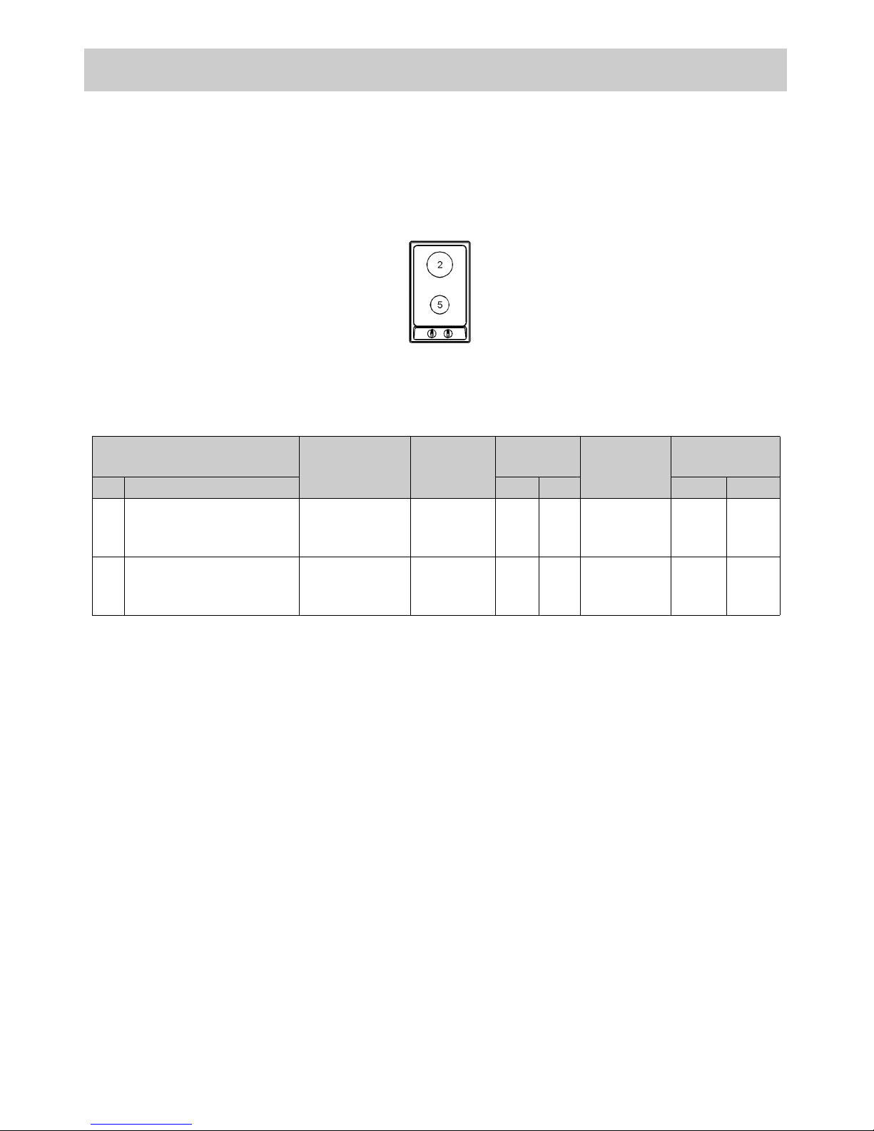
BURNER ARRANGEMENT ON THE HOT PLATE
CONVERSIONS
BURNERS
GAS
NORMAL
PRESSURE
mbar
NORMAL
RATE
INJECTOR
DIAMETER
1/100 mm
NOMINAL HEAT
INPUT (W)
N°
DESCRIPTION
g/h l/h Min. Max.
2
RAPID
G30 - BUTANE
G31 - PROPANE
G20 - NATURAL
28 - 30
37
20
218
214
286
85
85
115 Y
750
750
750
3000
3000
3000
5
AUXILIARY
G30 - BUTANE
G31 - PROPANE
G20 - NATURAL
28 - 30
37
20
73
71
95
50
50
72 X
400
400
400
1000
1000
1000
TABLE
12
Always disconnect the appliance from the
electricity and gas mains before proceeding
with any servicing operation.
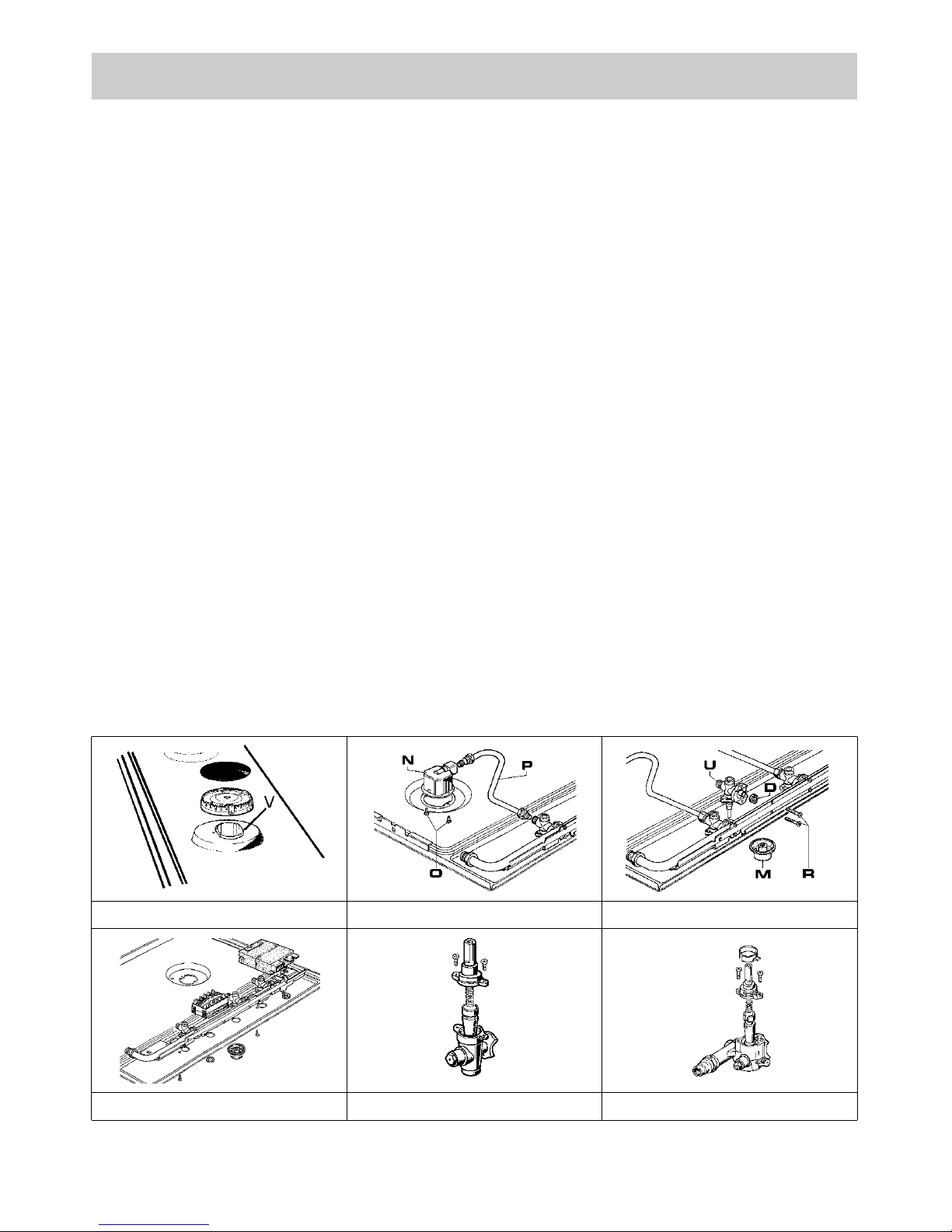
11) REPLACING HOT PLATE PARTS
When parts housed within the hot plate need
replacing, it is first necessary to remove the hot
plate itself from the cabinet, to overturn it, unscrew
screws “V” and to remove part (see fig. 14).
After having carried out the above listed operations,
the burners (fig. 15), taps (fig. 16) and electrical
components can all be replaced (fig. 17).
It is advisable to change seal “D” whenever a tap is
replaced to ensure a perfect tightness.
Greasing the taps (see fig. 18 - 19)
If a tap becomes stiff to operate, it must be
immediately greased in compliance with the
following instructions:
- remove the tap.
- Clean the cone and its housing using a cloth
soaked in diluent.
- Lightly spread the cone with the relative grease.
- Fit the cone back in place, operate it several times
and then remove it again. Eliminate any excess
grease and check that the gas ducts have not
become clogged.
- Fit all parts back in place, complying with the
demounting order in reverse.
- The tight closure test must be done using a foamy
liquid. The use of the flame is prohibited.
To facilitate the servicing technician’s task, here is a
chart with the types and sections of the powering
cables and the ratings of the electrical components.
FIG. 17 FIG. 18 FIG. 19
FIG. 14 FIG. 15 FIG. 16
SERVICING
13
SERVICING
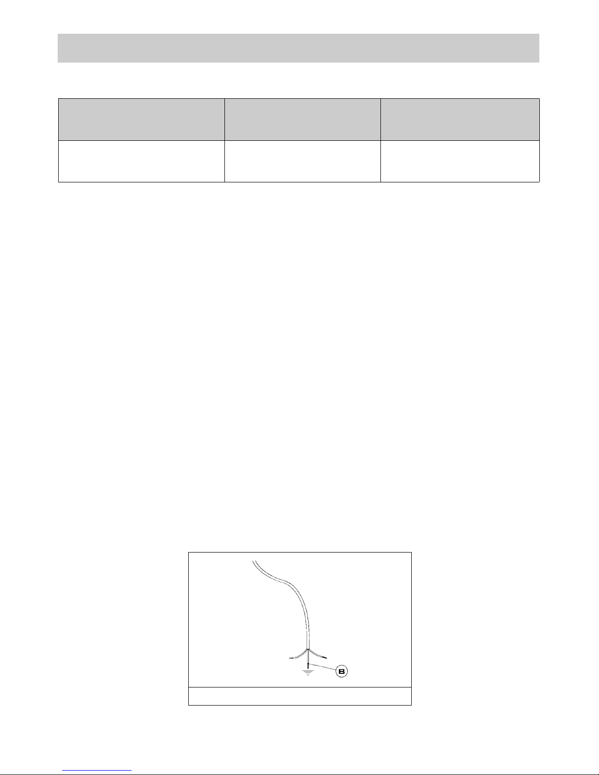
CABLE TYPES AND SECTIONS
ATTENTION!!!
If the power supply cable is replaced, the installer should leave the ground wire longer than the
phase conductors (fig. 20) and comply with the recommendations given in paragraph 8.
FIG. 20
TYPE OF
HOT PLATE
TYPE OF
CABLE
SINGLE - PHASE
POWER SUPPLY
Gas hot plate H05 RR - F Section 3 x 0.75 mm
2
14
TECHNICAL DATA ON THE DATA LABEL
5 BURNERS (70)
CATEGORY: II
2H3+
BUTANE = 28 - 30 mbar
PROPANE = 37 mbar
NATURAL = 20 mbar
Σ Qn Gas Natural = 10.05 kW
Σ Qn LPG= 731 g/h
VOLTAGE = 220 - 240 V ~
FREQUENCY = 50/60 Hz
2 BURNERS (30)
CATEGORY: II
2H3+
BUTANE = 28 - 30 mbar
PROPANE = 37 mbar
NATURAL = 20 mbar
Σ Qn Gas Natural = 4 kW
Σ Qn LPG= 291 g/h
VOLTAGE = 220 - 240 V ~
FREQUENCY = 50/60 Hz
15
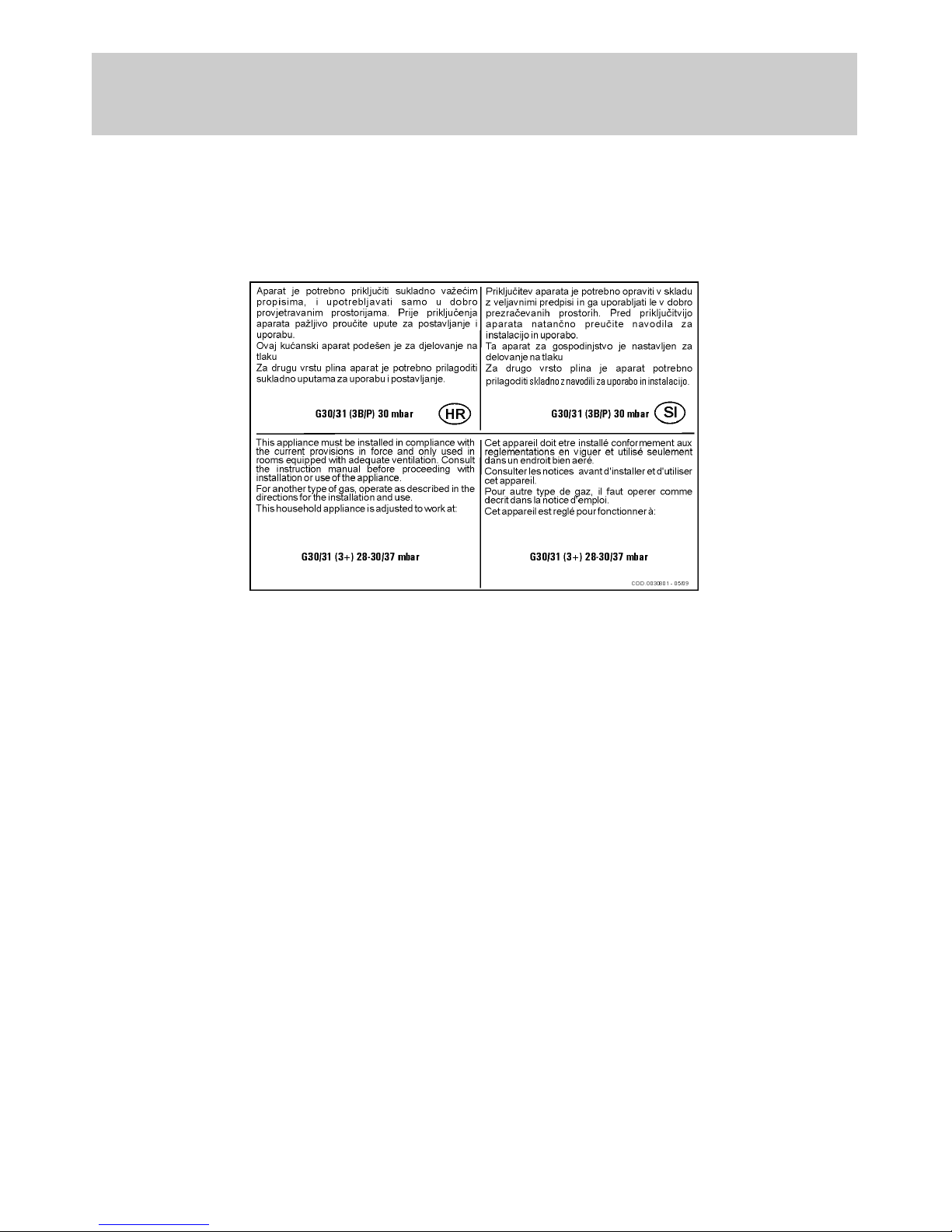
TECHNICAL DATA FOR THE
APPLIANCE GAS REGULATION

16
Before leaving the factory, this appliance will have been tested and regulated by expert and specialized
personnel in order to guarantee the best performances.
Any repairs or adjustments which may be subsequently required may only be carried out by qualified
personnel with the utmost care and attention.
For this reason, always contact your Dealer or our nearest After Sales Service Center whenever repairs
or adjustments are required, specifying the type of fault and the model of the appliance in your
possession.
Please also note that genuine spare parts are only available from our After Sales Service Centers and
authorized retail outlets.
The above data are printed on the data label put on the inferior part of the appliance and on the packing
label.
The above informations give to the technical assistant the possibility to get fit spare parts and a heavensent intervention. We suggest to fill the table below.
MARK: ........................................................................
MODEL: ......................................................................
SERIES: ......................................................................
TECHNICAL ASSISTANCE AND SPARE PARTS
This appliance is marked according to the European directive 2002/96/EC on Waste Electrical and
Electronic Equipment (WEEE).
This guideline is the frame of a European-wide validity of return and recycling on Waste Electrical and
Electronic Equipment.
Instructions d’installation
et avertissements d’entretien
G760AX1 - 236632
G34AX1 - 249046
Manuel d’instruction
G760AX1 - 236632
G34AX1 - 249046
COD. 04037KESTGOA (04037FR) - 14.07.2010
18
1 Brûleur triple couronne de 3100 W
2 Brûleur rapide de 2800 ÷ 3000 W
3 Brûleur semi-rapide droite frontal de 1400 W
4 Brûleur semi-rapide gauche derniere de 1750 W
5 Brûleur auxiliaire de 1000 W
6 Grille en acier émaillé à 2 feux
7 Grille en acier émaillé centrale
8 Bouton de commande du brûleur n° 1
9 Bouton de commande du brûleur n° 2
10 Bouton de commande du brûleur n° 3
11 Bouton de commande du brûleur n° 4
12 Bouton de commande du brûleur n° 5
13 Bouton d’allumage électrique
Attention: cet appareil à été conçu pour l’emploi domestique, dans habitat domestiques et de
part de sujets privés.
DESCRIPTION DES TABLES DE CUISSON
MODÈLE: G34AX1 - 249046
MODÈLE: G760AX1 - 236632
19
FIG. 1 FIG. 2
1) BRULEURS
Sur le bandeau de commande on a réalisé en
sérigraphie, sous chaque brûleur, un schéma
indiquant à quel brûleur correspond le bouton. Après
avoir ouvert le robinet du gaz ou de la bouteille de
gaz, allumer les brûleurs en suivant la description ciaprès:
- allumage manuel
Enfoncer et tourner dans le sens inverse des
aiguilles d’une montre le bouton correspondant au
brûleur à utiliser, l’amener sur la position Maximum
(grande flamme fig. 1) et approcher une allumette
du brûleur.
- Allumage électrique
Enfoncer et tourner dans le sens inverse des
aiguilles d’une montre le bouton correspondant au
brûleur à utiliser, l’amener sur la position Maximum
(grande flamme fig.1) puis enfoncer et relâcher le
bouton d’allumage.
- Allumage électrique automatique
Enfoncer et tourner dans le sens inverse des
aiguilles d’une montre le bouton correspondant au
brûleur à utiliser, l’amener sur la position Maximum
(grande flamme fig. 1) puis enfoncer le bouton à
fond.
-
Allumage des brûleurs dotés d’un
thermocouple de sécurité
Avec les brûleurs dotés d’un thermocouple de
sécurité, il faut tourner dans le sens inverse des
aiguilles d’une montre le bouton correspondant au
brûleur à utiliser, l’amener sur la position Maximum
(grande flamme fig. 1) jusqu’à entendre un léger
déclic puis enfoncer le bouton et répéter les
opérations indiquées précédemment.
Lorsque l’allumage a eu lieu, maintenir le bouton
enfoncé pendant 10 secondes environ.
COMMENT UTILISER LES BRÛLEURS
Pour obtenir le rendement maximal avec une
consommation minimale de gaz, il est utile de
rappeler les points suivants:
- utiliser pour chaque brûleur des casseroles
adéquates (voir le tableau suivant et la fig. 2).
- Lorsque l’ébullition a été atteinte, amener le
bouton sur la position Minimum (petite flamme fig. 1).
- Toujours utiliser des casseroles avec un
couvercle.
- Utilisez seulement récipients avec fond plat.
AVERTISSEMENTS:
- on ne peut procéde r à l’allumage des
brûleurs dotés d’un thermocouple de sécurité
que lorsque le bouton est sur la position
Maximum (grande flamme fig. 1).
- En cas de coupu re d e cour ant, on peut
allumer les brûleurs avec des allumettes.
- Durant l’utilisation des brûleurs, ne pas
laisser l’appareil sans surveillance et en
éloigner les enfants. S’assurer en particulier
que les poig nées des casser oles son t
correctement positionnées et surveiller la
cuisson des aliments qui requièrent des
huiles et des graisses car elles sont
facilement inflammables.
- Ne pas util iser de spray à proximité de
l’appareil lorsqu’il est en fonction.
- Si la table de cu isson est dotée d ’un
couvercle, avant de le soulever, éliminer tous
les résidus d’aliments qui ont débordé sur la
surface. Si l’appareil est doté d’un couvercle
en verre, ce dernier peut éclater lorsqu’il est
chauffé. Eteindre et laisser refroidir tous les
brûleurs avant de refermer le couvercle.
- L’utilisation de cet appareil est interdite aux
personnes (y compr is les enfant s) aux
capacités physiques et mentales réduites, ou
sans aucune exp érience d'utilisatio n
d’appareillages électriques, à moins qu’elles
ne soient surveillées ou instruites par des
personnes adultes et responsables de leur
sécurité. On recommande de surveiller les
enfants pour s'assurer qu'ils ne jouent pas
avec l'appareil.
- On conseille d’utiliser des récipients qui
dépassent du bord du plan de cuisson.
UTILISATION
Brûleurs
Puissances WØ Casseroles
(cm)
Triple couronne 3100 24 ÷ 26
Rapide 2800÷3000 20 ÷ 22
Semi-rapide droite frontal 1400 16 ÷ 18
Semi-rapide gauche derniere 1750 16 ÷ 18
Auxiliaire 1000 10 ÷ 14
20
UTILISATION
Remarque:
l’utilisation d’un appareil de cuisson au gaz produit de la chaleur et de l’humidité dans la pièce où il
est installé. Il est donc nécessaire d’assurer une bonne aération de la pièce en veillant à ne pas
obstruer les ouvertures pour la ventilation naturelle (fig. 3) et en mettant en marche le dispositif
mécanique d’aération (hotte aspirante ou électro-ventilateur fig. 4 et fig. 5).
En cas d’utilisation intensive ou prolongée de l’appareil, une aération supplémentaire peut s’avérer
nécessaire, comme par exemple l’ouverture d’une fenêtre, ou bien une aération plus efficace en
augmentant la puissance de l’aspiration mécanique si elle est prévue.
FIG. 3 FIG. 4 FIG. 5
(*) ENTREE D’AIR: VOIR CHAPITRE INSTALLATION (PARAGRAPHES 5 ET 6)
21
NETTOYAGE
ATTENTION:
avant toute opération de nettoyage, débrancher
l’appareil et couper le gaz.
2) PLAN DE TRAVAIL
Si on veut conserver la brillance de la table, il est très
important de la laver après chaque utilisation à l’eau
savonneuse tiède puis de la rincer et de la sécher.
Laver de la même manière les grilles émaillées, les
couvercles émaillés “C” des répartiteurs de flamme
et les injecteurs “T” (voir fig. 6).
Le nettoyage doit être effectué lorsque la table et les
composants ne sont pas chauds et on ne doit pas
utiliser d’éponges abrasives ni de produits abrasifs
en poudre ni de sprays corrosifs. Eviter que le
vinaigre, le café, le lait, l’eau salée, le jus de citron ou
de tomate ne restent trop longtemps au contact des
surfaces.
AVERTISSEMENTS:
lors du remontage des composants, il est
conseillé de s’en tenir aux recommandations
suivantes:
- vérifier que les trous de sortie de gaz des
répartiteurs de flamme “T” (fig. 6) ne sont pas
bouchés par des corps étrangers.
- S’assurer que le couvercle émaillé du
répartiteur de flamme “C” (fig. 6) est
correctement positionné sur le répartiteur de
flamme, c’est à dire qu’il est dans une position
parfaitement stable.
- La position exacte de la grille est définie par
des coins arrondis qu’il faut positionner vers
le bord latéral de la table.
- Si l’ouverture ou la fermeture d’un robinet
devait s’avérer difficile, ne pas forcer, mais
demander l’intervention urgente du Service
d’Assistance Technique.
- Ne nettoyez pas le plan avec de jets de vapeur.
FIG. 6
22
INSTALLATION
INFORMATIONS TECHNIQUES A
L’ATTENTION DES INSTALLATEURS
L’installation, tous les réglages, les
transformations et les entretiens mentionnés
dans ce chapitre doivent être effectués
exclusivement par du personnel qualifié.
Une mauvaise installation peut provoquer des
accidents de personnes et d’animaux ainsi que
des dégâts matériels qui ne sont pas imputables
au constructeur.
Les dispositifs de sécurité ou de réglage
automatique des appareils pour la durée de vie
de l’installation pourront être modifiés
uniquement par le constructeur ou par le
fournisseur dûment autorisé.
3) MISE EN PLACE DE LA TABLE DE CUISSON
Après avoir enlevé l’emballage externe et interne
des différentes pièces mobiles, s’assurer que la
table est intacte. En cas de doute, ne pas utiliser
l’appareil et s’adresser à du personnel qualifié.
Les éléments de l’emballage (carton, sachets,
polystyrène expansé, clous) ne doivent pas
être laissés à la portée des enfants car ils
représentent des sources potentielles de
danger.
On doit pratiquer, sur le plan du meuble à éléments,
une ouverture pour l’encastrement ayant les
dimensions exprimées en millimètres indiquées
dans les fig. 7, en veillant à respecter les distances
critiques entre la table, les parois latérales,
postérieure et supérieure (voir fig. 7 et 8).
L’appareil doit figurer en classe 3 et il est donc
soumis à toutes les prescriptions prévues par
les normes correspondantes.
4) FIXATION DE LA TABLE DE CUISSON
La table est équipée d’une garniture spéciale pour
éviter toute infiltration de liquide dans le meuble.
Pour appliquer correctement cette garniture, prière
de s’en tenir scrupuleusement à ce qui est spécifié
ci-après:
- détacher les bandes de la garniture de leur
supp ort en veillant à c e que la protec tion
transparente reste fixée à la garniture.
- Renverser la table de cuisson et positionner
correctement la garniture “E” (fig. 9) sous le bord
de la table, de manière à ce que le côté externe
de garniture coïncide parfaitement avec le bord
périmétral externe de la table. Les extrémités
des bandes doivent coïnci der sans se
chevaucher.
- Faire adhérer la garniture à la table de cuisson,
de manière uniforme et sûre, en la pressant avec
les doigts, puis retirer la bande de protection en
papier de la garniture et positionner la table dans
le trou pratiqué sur le plan de travail.
- La bloquer au moyen des brides “S”, en ayant
soin d’enfiler la partie saillante dans la fente “H”
réalisée sur le fond et en serrant la vis “F”
jusqu’à ce que la bride ne bloque plus la table de
cuisson sur le plan de travail (voir fig. 10).
- Il est nécessaire d'éviter le contact accidentel avec le
fond de surchauffe de la fraise-mère, pendant le
fonctionnement, de mettre une insertion en bois, fixée
par des vis, à une distance minimum de 60 millimètres
du dessus (voir la fig. 7).
DIMENSIONS A RESPECTER (en mm)
FIG. 7 FIG. 8 FIG. 9
FIG. 10
A B C D E
2F (30) 282 482 59 59 100 min.
5F (70) 553 473 63.5 63.5 175 min.

23
PRESCRIPTIONS IMPORTANTES
POUR L'INSTALLATION
Information pour l'installateur: les parois
latérales éventuelles ne doivent pas dépasser
en hauteur la table de cuisson. En outre, la
paroi postérieure ainsi que l es surfa ces
adjacentes et environnantes doivent résister à
une surchauffe de 65 K.
Le produit collant qui unit le laminé plastique
au meuble doit résister à des températures
supérieures à 150 °C pour évit er le
décollement du revêtement.
L'installation de l'appareil doit être conforme
aux normes en vigueur.
Cet appareil n'est pas raccordé à un dispositif
d'évacuation des produits de la combustion. Il
doit donc être raccordé conformément aux
règles d'installation mentionnées ci-dessus. Il
faudra prêter une attention particulière aux
disposition s appl icables en m atière de
ventilation et d'aération.
5) AERATION DE LA PIECE
Le local où est installé l’appareil doit être ventilé en
permanence pour garantir le bon fonctionnement de
l’appareil. La quantité d’air nécessaire est celle
utilisée par la combustion des gaz et par la
ventilation de la pièce dont le volume devra être au
moins de 20 m3. L’aération naturelle directe doit être
assurée par des ouvertures permanentes d’une
section minimum de 100 cm2(voir fig. 3)
aménagées sur les parois extérieures de la pièce. Il
ne doit pas être possible d’obstruer ces ouvertures.
L’aération indirecte est également admise en
prélevant l’air d’un local adjacent. Dans ce cas
respecter formellement les normes en vigueur.
ATTENTION: si les brûleurs de la table de
cuisson sont dépourvus du thermocouple de
sécurité, l’ouverture de ventilation doit avoir
une surface minimale de 200 cm2.
6) EMPLACEMENT ET EVACUATION
DES PRODUITS DE LA COMBUSTION
Les tables de cuisson doivent toujours évacuer les
produits de la combustion dans des hottes reliées à
des conduits ou débouchant directement à
l’extérieur (voir fig. 4). Lorsqu’il n’est pas possible
de monter une hotte, vous pouvez utiliser un
ventilateur installé sur la fenêtre ou sur une paroi
donnant vers l’extérieur, dans le respect des
normes en vigueur sur l’aération de la pièce. Ce
dispositif sera mis en marche en même temps que
l’appareil (voir fig. 5).
7) RACCORDEMENT AU GAZ
Avant de raccorder l'appareil, s'assurer que les
données figurant sur l'étiquette signalétique
appliquée sur la partie inférieure du caisson
sont compatibles avec celles du réseau de
distribution du gaz.
Une étiquette imprimée de ce livret ainsi qu'une
étiquette appliquée sur la partie inférieure du
caisson indiquent les conditions de réglage de
l'appareil: type de gaz et pression d'exercice.
Quand le gaz est distribué par une canalisation,
l'appareil doit être raccordé à l'installation d'arrivée
du gaz selon la norme:
o soit au moyen d'un tuyau métallique rigide en acier,
dont les jonctions doivent être réalisées au moyen
de raccords filetés conformément à la norme en
vigueur.
o Soit au moyen d'un tuyau de cuivre, dont les
jonctions doivent être réalisées au moyen de
raccords à garniture mécanique.
o Soit au moyen d'un tuyau flexible en acier
inoxydable à paroi continue, avec une extension
maximale de 2 mètres et des garnitures d'étanchéité
conforme aux normes.
Lorsque le gaz est directement distribué à partir
d'une bouteille, l'appareil, alimenté par un
régulateur de pression, doit être raccordé:
o soit au moyen d'un tuyau de cuivre, dont les
jonctions doivent être réalisées au moyen de
raccords à garniture mécanique.
o Soit au moyen d'un tuyau flexible en acier
inoxydable à paroi continue, avec une extension
maximale de 2 mètres et des garnitures d'étanchéité
conforme aux normes. Il est conseillé d'appliquer sur
le tuyau flexible l'adaptateur spécial, couramment
vendu dans le commerce, pour faciliter le
raccordement à l'embout du régulateur de pression
monté sur la bouteille.
o Soit par tube souple en caoutchouc d'une lungueur
allant de 400 à 1500 mm, fixé solidement à l'embout
par un collier de sécurité.
À l'extrémité de raccordement, vérifiez le gasproof
en utilisant une solution de savon, jamais une
flamme.
AVERTISSEMENTS:
- le raccord d'entrée du gaz de l'appareil est
fileté 1/2" gaz cylindrique mâle conformément
aux normes ISO 228-1.
- Le tuyau flexible ou le tube souple doit être
installé de manière à ne pas être en contact
avec des parties mobiles du module
encastrable (par exemple des tiroirs) et ne doit
pas traverser des casiers pouvant être
remplis.
- L'appareil est conforme aux prescriptions des
Directives Européennes suivantes:
CEE 90/396 + 93/68 concernantes la sécurité
gaz.
En outre, les parois et les surfaces adjacentes et
environnantes doivent résister à une surchauffe
de 65 K.
INSTALLATION
24
8) RACCORDEMENT ELECTRIQUE
Le raccordement électrique doit être effectué
conformément aux normes et aux dispositions
légales en vigueur.
Avant de procéder au raccordement, vérifier que:
- la portée électrique de l’installation et des prises
de courant sont appropriées à la puissance
maximale de l’appareil (voir l’étiquette appliquée
sur la partie inférieure du caisson).
- La prise ou l’installation sont munies d’un
raccordement efficace à la terre conformément
aux normes et aux dispositions légales en
vigueur. Le fabricant décline toute responsabilité
en cas de non respect de ces dispositions.
Lorsque le branchement au réseau
d’alimentation est effectué par l’intermédiaire
d’une prise:
- appliquer au câble d’alimentation “C”, s’il en est
dépourvu, une fiche normalisée adaptée à la
charge indiquée sur l’étiquette signalétique.
- Raccorder les fils d’après le schéma de la fig. 11
en ayant soin de respecter les correspondances
suivantes:
lettre L (phase) = fil marron;
lettre N (neutre) = fil bleu;
symbole de terre = fil vert-jaune.
- Le câble d’alimentation doit être positionné de
manière à ce qu’à aucun endroit il ne puisse subir
une surchauffe de 75 K.
- Ne pas utiliser pour le raccordement des
réductions, des adaptateurs ou des dérivateurs
car ils risqueraient de provoquer de faux contacts
suivis de surchauffes dangereuses.
- La sortie doit être accessible après la fonction
intégrée.
Lorsque le raccordement est directement
réalisé sur le réseau électrique:
- interposer entre l’appareil et le réseau un
interrupteur omnipolaire, dimensionné à la
char ge de l’ appare il, avec une ouverture
minimale entre les contacts de 3 mm.
- Ne pas oublier que le câble de mise à la terre ne
doit pas être interrompu par l’interrupteur.
- Alternative: le réseau électrique peut également
être protégé au moyen d ’un inte rrupteu r
différentiel à haute sensibilité.
Il est vivement recommandé de fixer le fil de terre
vert-jaune à un circuit efficace de mise à la terre.
AVERTISSEMENTS:
tous nos appareils sont conçus et construits
selon les normes européennes EN 60 335-1,
EN 60 335-2-6 et EN 60 335-2-102, et les
amendements correspondants.
L’appareil est conforme aux Directives
Européennes suivantes:
- CEE 2004/108/CE relative à la compatibilité
électromagnétique.
- CEE 2006/95 relative à la sécurité électrique.
INSTALLATION
FIG. 11
 Loading...