

Page 1
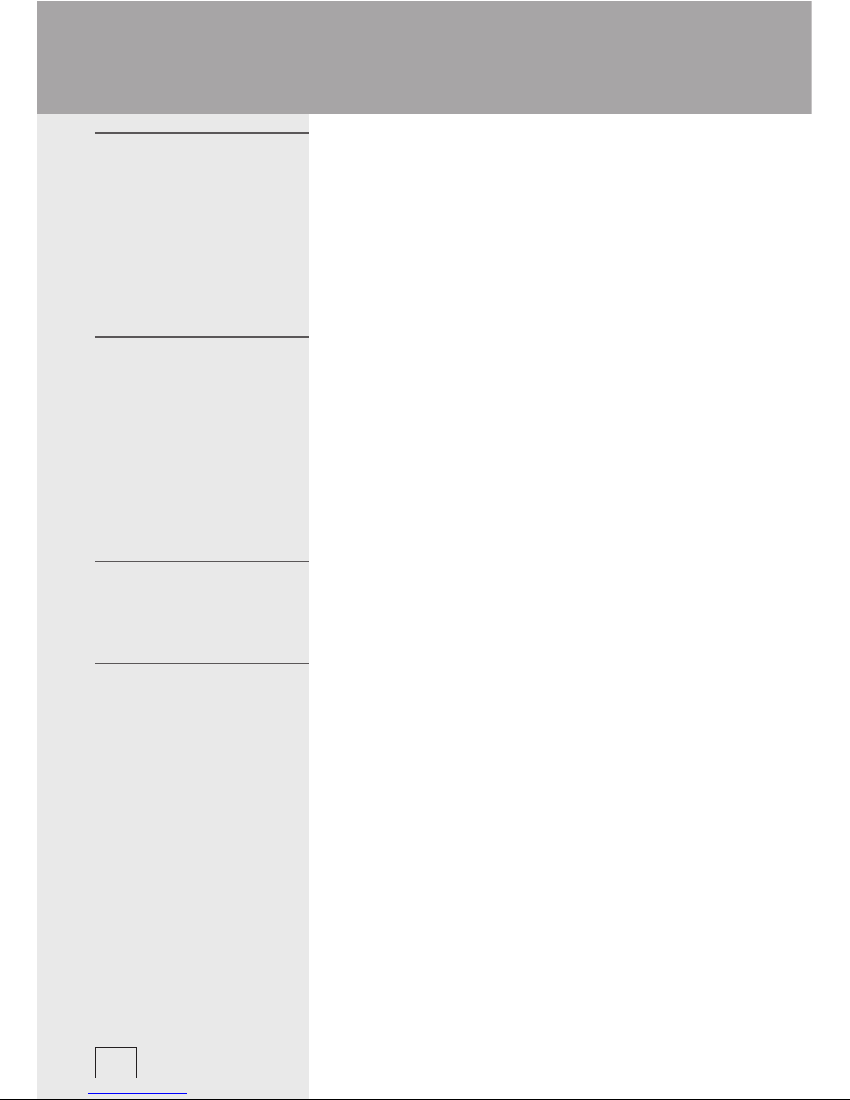
Integrated gas hob
4106...
4107...
Instructions for use, mounting and connection
EN
Page 2
559100
This electric integrated gas cooker is manufactured for
household use.
Our appliances are packed in environmentally friendly materials
that may be recycled, deposited or destroyed without any hazard
to the environment. Such packaging materials are also labelled
accordingly.
Once the life cycle your appliance is over, make sure not to
pollute the environment, and deliver it to the authorized collectors
of old household appliances.
Instructions for use have been prepared for the user, and
describe the appliance and the way it is handled. These
instructions are intended for various types of the appliance,
so you may fi nd some descriptions for the functions that your
particular appliance may not have.
These instructions are only valid if the country symbol is
indicated on the appliance. If there is NO country symbol in the
appliance, technical instructions should be observed for adapting
the appliance to comply with the requirements and regulations
for use in your country.
The connections must be carried out in accordance with the
instructions supplied with the appliance, and in compliance with
the recognized standards.
Connections must be performed by qualifi ed personnel only.
Rating plate with the basic information is fi xed to the bottom side
of the hob.
Dear Buyer,
Instructions for use
Instructions for
connecting the appliance
Rating plate
Safety precautions ...................................................... 3
Description of the appliance ...................................... 5
Gas burner control ......................................................6
Cleaning and maintenance ......................................... 9
Troubleshooting guide .............................................. 11
Installation instructions ............................................ 12
Connecting the cooktop to the power mains ..........14
Gas connection ......................................................... 16
Nozzle chart - glas ceramic hob ............................... 19
Technical information ...............................................21
2
Integrated gas hob EN
Page 3
559100
• This appliance can be used by children aged from 8 years and
above and persons with educed physical, sensory or metal
capabilities or lack of experience and knowledge if they have
been given supervision or instruction concerning use of the
appliance in a safe way and understand the hazards involved.
Children shall not play with the appliance. Cleaning and user
maintenance shall not be made by children without supervision.
• WARNING: The appliance and its accessible parts become hot
during use. Care should be taken to avoid touching heating
elements. Children less than 8 years of age shall be kept away
unless continuously supervised.
• WARNING: Danger of fi re: do not store items on the cooking
surfaces.
• WARNING: Unattended cooking on a hob with fat or oil can be
dangerous and may result in fi re. Never try to extinguish a fi re
with water, but switch off the appliance and then cover fl ame
with a lid or a damp cloth.
• WARNING: If the surface is cracked, switch off the appliance to
avoid the possibility of electric shock.
• Do not use steam cleaners or high-pressure cleaners to clean
the cooking hob, as this may result in an electric shock.
• The appliance is not intended to be controlled by external timers
or special control systems.
• To avoid any possible hazard, the appliance may be installed by qualifi ed personnel only.
• CAUTION: The use of a gas cooking appliance results in the production heat, moisture and products
of combustion in the room in which it is installed. Ensure that the kitchen is well ventilated especially
when the appliance is in use: keep natural ventilation holes open or install a mechanical ventilation
device (mechanical extractor hood).
• Prolonged intensive use of the appliance may call for additional ventilation, for example opening of a
window, or more effective ventilation, for example increasing the level of mechanical ventilation where
present.
• CAUTION: This appliance is for cooking purposes only. It must not be used for other purposes, for
example room heating.
• In case you should smell gas in the room, immediately shut the main gas supply valve at the gas tank
or the gas installation, extinguish all open fi res (including the cigarette), and abundantly ventilate the
room. Do not switch any electrical devices on, and call the qualifi ed gas personnel at once!
• The main gas supply valve must be shut also in case you do not intend to use the gas burners for any
considerable amount of time (i.e. leaving for a vacation).
• Particular cooktop areas (especially the hotplates) may become very hot during operation. Do not let
Safety precautions
3
Page 4
559100
small children in the vicinity of the cooker and warn them about the danger of burns.
• Hot grease is highly infl ammable, so pay extra attention when preparing food with grease or oil. Frying
in fat or oil (chips) may be carried out only under constant surveillance.
• Hotplates may not operate empty, without dishes placed on top.
• Never use the appliance for heating of the room.
• In case of any detected malfunction immediately disconnect the appliance from the mains supply and
call the service.
• The appliance is manufactured in compliance with the relevant effective safety standards.
Nevertheless, we strongly recommend that persons with impaired physical, motoric, or mental
capacity, or persons with inadequate experience or knowledge, do not use the appliance unless
attended by a qualifi ed person. The same recommendation applies when the appliance is used by
persons of less-than-legal age.
The symbol on the product or on its packaging indicates that this product may not
be treated as household waste. Instead it shall be handed over to the applicable
collection point for the recycling of electrical and electronic equipment. By ensuring
this product is disposed of correctly, you will help prevent potential negative consequences
for the environment and human health, which could otherwise be caused by inappropriate
waste handling of this product. For more detailed information about recycling of this
product, please contact your local city offi ce, your household waste disposal service or the
shop where you purchased the product.
Special warning for glass ceramic hob
• Glass ceramic hob is tough, but not unbreakable. Should any sharp or heavy objects fall upon
the surface, they may cause damage.
• CAUTION: In case of hotplate glass breakage:
- Immediately shut off all the burners and isolate them from the power supply.
- Do not touch the appliance surface.
- Do not use the appliance.
• Sand particles or rough wrought iron pot bottoms may also produce scratches upon the glass
ceramic surface.
• In case the glass ceramic hob is used as a worktop it may be damaged or scratched. Never heat
up the food in aluminium foil or plastic dishes, otherwise you may damage the hob or cause
melting of material and fi re.
4
Page 5
559100
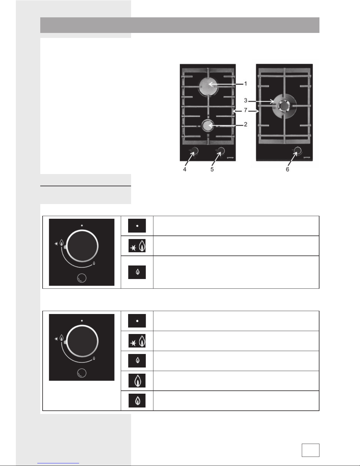
Hob surface is made of ceramic glass and is fi tted with gas burners and control buttons (depending
upon the model).
1. Rear burner – large (B)
2. Front burner – small (A1)
3. Double burner (Wok)
4. Front burner control button
5. Rear burner control button
6. Control button of the double burner
7. Cast iron cooking grating
Twin burner model
Gas faucet closed
High power
Low power
Single – Double burner (WOK)
Gas faucet closed
High power - inner burner circle
Low power - inner burner circle
High power - inner, intermediate and exterior burner circle
Low power - inner, intermediate and exterior burner circle
5
Description of the appliance
Control buttons
Page 6
559100
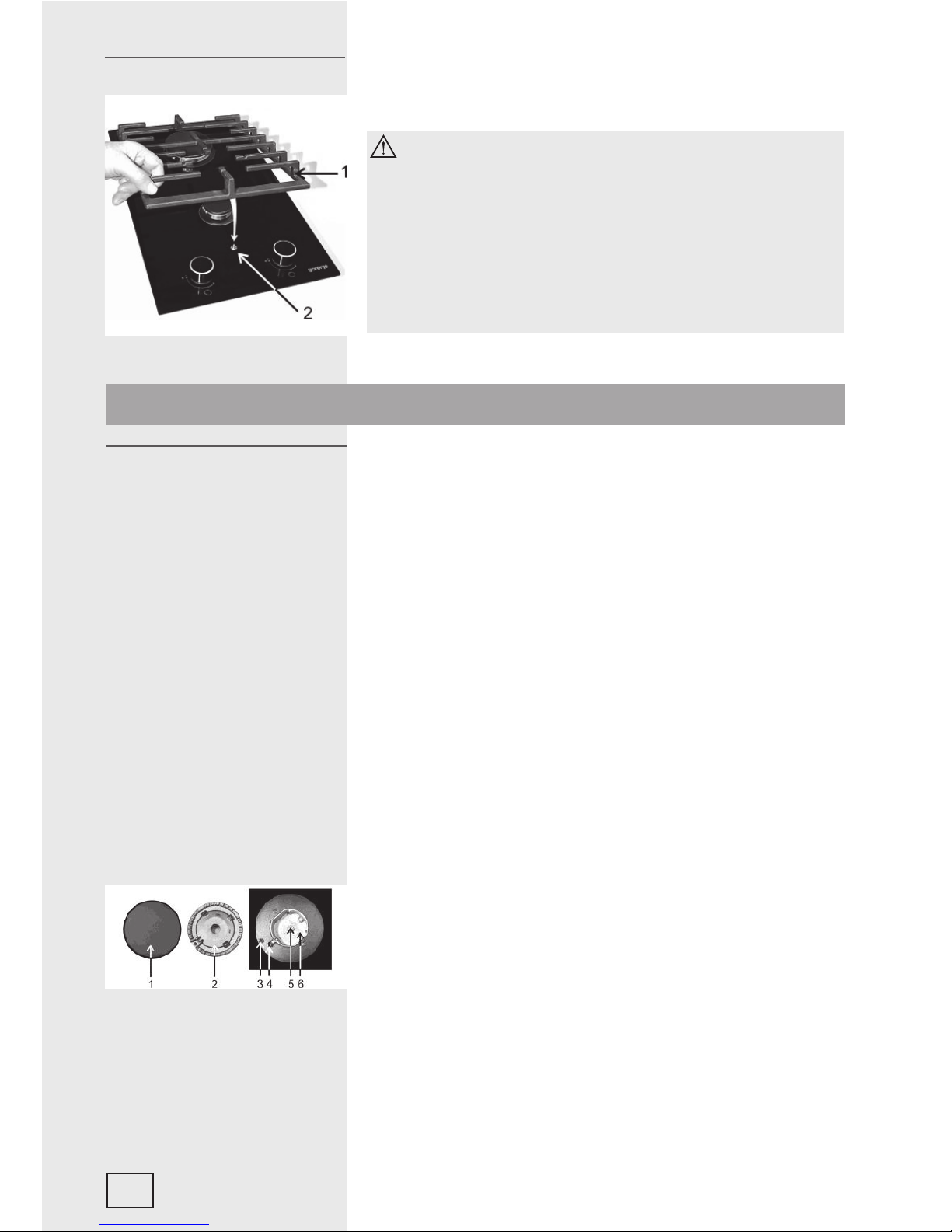
1. Cast iron cooking grating.
2. Centering – setting pin of the grating.
The cast iron cooking grating is heated up during
appliance operation and remains hot during some
time even after extinction of the gas burners.
Therefore be always careful (also at manipulation
with the control knobs), for to prevent burning!
The cooking grating at the burner can be loaded with
an utensil of total weight of 15 kg.
Put the utensils on the cooking grating without
impact!
The location of grating
• Never use cooking zones without dishes, or for heating the
ambience!
• Keep the cooktop clean, since dirt and stains have adversary
effect on the functionality of burners.
• If you like your food to be crisp, fi rst set the burner to the
maximum and continue cooking at minimum power.
• Always provide adequate quantity of water when cooking in
the pressure cooker. Lack of water may cause damage to the
dish and to the cooker.
• Be very precise when placing the burner crown cap upon the
crown. Always keep the crown nozzles clean and free.
• In certain models hob burners are thermally protected. If the
fl ame is accidentally extinguished (spilled boiling, draft of wind,
etc.) gas inlet is automatically shut, and gas can not escape
into the room.
• In case of thermally non-protected burners, gas uncontrollably
escapes into the room without warning!
a) Large and auxiliary burner
1. Burner crown cap
2. Burner crown with burner cap support
3. Thermal probe (thermally protected burners only, only
certain models)
4. Ignition plug
5. Nozzle
6. Bowl of the burner
Safety cautions in regard
to the cooking zones
a)
6
Gas burner control
Page 7
559100
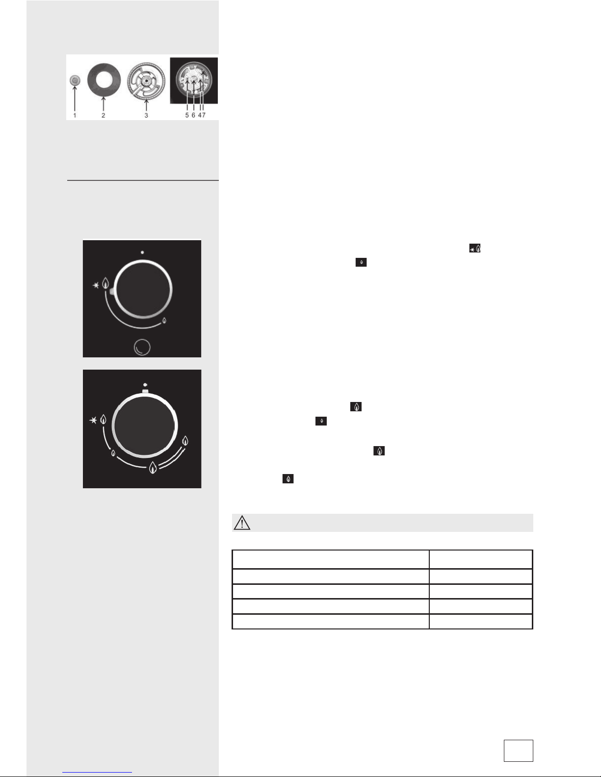
b) Double burner (wok) - certain models only
1. Burner cup WOK
2. Burner crown cap
3. Burner crown with burner cap support
4. Thermal probe (thermally protected burners only, only
certain models)
5. Ignition plug
6. Nozzle
7. Nozzle
Twin burner model:
• Cooking burners are controlled with relevant burner buttons.
These are marked with small fl ame and large fl ame symbols
(see section ‘Description of the appliance’).
• Always turn buttons over the large fl ame symbo
towards
the small fl ame symbol
and back. Operating positions are
all positions between the two symbols.
• Burners are ignited by means of ignition device, fi xed
adjacent to each burner (certain models only).
Models with one double burner (WOK):
• Cooking burners are controlled with relevant burner buttons.
These are marked with small fl ame and large fl ame symbols
(see section ‘Description of the appliance’).
• Turn the knob to the left over the large fl ame position for the
interior burner section
to the small fl ame of the interior
burner section . Here the knob needs to be pushed in order
to turn it to the large fl ame position of the interior, intermediate
and exterior burner section
and further to the position of
small fl ame for the interior, intermediate and exterior burner
section
then turn it back. Working position is between the
large and the small fl ame symbol.
Always push the button in before starting to turn it!
Burner type Dish diameter
Large (3kW) 220 - 260mm
Auxiliary (1 kW) 120 - 180mm
Double (WOK) – interior fl ame (1kW) 120 - 180mm
Double (WOK) – all fl ame (4,5kW) 220 - 300mm
• To ignite the burner, press the selected burner button and turn
it to the maximum power position (large fl ame symbol). Electric
spark from the ignition device ignites the gas.
b)
Ignition and operation of
burners
7
Page 8
559100
• If the ignition device is out of order (power failure or humidity),
use a match or a lighter to ignite the gas. Keep the button
pressed for approximately 10 seconds after ignition to stabilize
the fl ame.
• After that you can set the burning power between high and low
position to suit your cooking requirements. Button positions
between
, and are not recommended. In these
positions the fl ame is not stabilized and may be extinguished.
If you failed to ignite the burner after 15 seconds,
shut the burner off and wait for at least one minute
before the next attempt.
If the burner fl ame goes out (for whatever reason),
shut the burner off and wait for at least one minute
before next attempt.
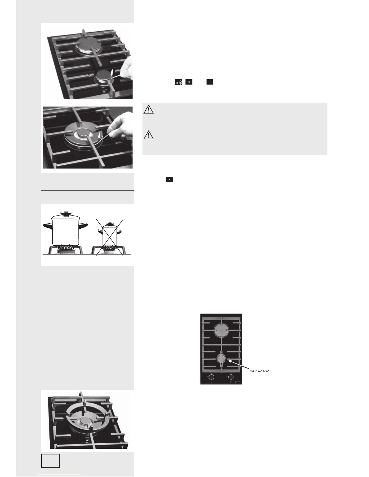
To shut the burner off turn the button to the right, to the OFF
position .
• Selection of the adequate dish size ensures optimized
cooking time and consumption of gas. Diameter of the dish is
of utmost importance.
• The fl ame reaching over the edge of the small diameter
dish may destroy the dish, while the consumption of gas is
increased.
• Gas needs oxigen for burning. In case of excessively large
dish diameter the oxigen supply is insuffi cient, consequently
reducing the burning capacity.
Grating for small pots
The grating for small pots can be bought afterwards
– order number SAP 428741
Wok accessory (for the double burner (Wok))
• Use the extension when preparing food in a Wok.
• Place the extension over the burner grid support.
Cookware
8
Page 9

559100
Cleaning and maintenance
The appliance should be cleaned with warm water, liquid detergent
and soft cloth. Never use aggressive cleaners and sharp objects.
Burned or dried food particles should be moistened with a wet
cloth and softened with an appropriate cleansing agent.
Stainless steel surfaces must be cleaned with special cleaners
for stainless steel. Apply a fi ne layer of the cleaner with a dry,
well absorbing cloth to the dried and cool surface, and rub in
the direction of the surface treatment. Stubborn stains should be
removed with wet cloth and then rubbed dry with a dry cloth to
the brilliance. Never use such cleaners for cleaning of aluminum.
Clean plastic and coated surfaces with liquid non-abrasive
cleaning agents using soft cloth.
• Gas grid, cooking area and burner components should be
cleaned with warm water and mild detergent for manual
washing of dishes.
• Thermal element and ignition device should be cleaned with soft
brush. To ensure perfect operation, these elements must always
be thoroughly clean.
• Clean the burner crown and cap. Specially check and clean gas
outlet openings on burner crown, and keep them dirt free at all
times.
• Upon completion of cleaning wipe all components dry and
replace them carefully to their respective slots. Oblique position
of components may cause troubled ignition of burners.
Note!
Crown caps are coated with black enamel. Discoloration
of caps, due to high temperatures, is inevitable, but it has no
adversary effect on normal operation of burners.
Cooktop burners
9
Page 10

559100
Ceramic glass hob should be cleaned only when completely
cooled down, preferably after each use, otherwise even the slightest
stains remaining after cooking may burn into the hob surface with
each following use.
For regular maintenance of ceramic-glass hob use special cleansing
agents, produced in such way to create protective fi lm upon the
surface.
Before each use, wipe the dust and other particles from the hob
- they may scratch the surface (Fig. 1).
Caution: use of steel wool, abrasive cleaning sponges, and abrasive
detergents can scratch the surface of the hob. The surface may
also be damaged by the use of aggressive sprays and inappropriate
liquid chemicals (Fig.1 and 2).
Pattern marks can be erased by the use of aggressive cleansing
agents or rough and damaged cookware bottoms (Fig. 2).
Minor stains are removed with moist soft cloth; after that the surface
should be wiped dry (Fig. 3).
Water stains are removed with gentle vinegar solution, but you must
not wipe the frame with it (certain models only), since it may lose its
glow. Never use any aggressive sprays or limestone removers (Fig.
3).
Major stains are removed with special ceramic-glass cleansers.
Follow strictly the manufacturer's instructions.
Be careful to remove any remains of cleansing agent from the hob
surface, otherwise they will be heated during the next use and can
damage the hob (fi g. 3).
Stubborn and burnt stains are removed with special ceramic- glass
scraper. Be careful, however, not to touch the hotplate surface with
the scraper handle (Fig. 4).
Handle the scraper with utmost care to avoid injuries!
Sugar and sugar containing food may permanently damage the
ceramic-glass hob surface (Fig.5), so the remains of sugar and
sugar containing food must be scraped off from the hob surface
immediately, when the hotplates are still hot (Fig. 4).
Discoloring of ceramic-glass hob has no effect whatsoever
on its operation and stability. In most cases, it appears as the
consequence of burnt in food remains, or as a result of dragging
pots and pans (especially aluminum or copper bottom cookware)
across the surface, and such discoloring is rather hard to remove.
Note: All described faults are mostly esthetical and do not affect
directly the operation of the appliance. Remedy of such faults is not
covered by warranty.
10
Cleaning and
maintenance of ceramicglass hob
fi g. 1
fi g. 2
fi g. 3
fi g. 4
fi g. 5
Page 11

559100
Fault Cause Remedy
Burner fl ame is not steady. Wrong setting of gas. Expert should set the gas escape
properly!
Burner fl ame suddenly changes. Incorrect assembly of burner
components.
Assemble the burner components
correctly!
Ignition of burners takes
excessively long.
Incorrect assembly of burner
components.
Assemble the burner components
correctly!
The fl ame goes off after ignition. Early release of control button.
Control button is not pushed in
fi rmly.
Keep the button pressed longer.
Before releasing the button, give
it one fi nal solid push.
The color of the cooking zone
gas grid has changed.
Normal situation, caused by the
high temperature.
Clean the grid with metal cleaning
agents.
Electric operations are generally
disturbed.
Fuse is burned. Check the fuse in the fuse box,
and replace if required.
Electric ignition of burners does
not function.
Food residues or detergent block
the contact between the ignition
device and the burner.
Open and clean carefully the
opening between the ignition
device and the burner.
Burner crown caps look ugly. Usual staining. Clean the crown cap with metal
cleaning agents.
Repairs may be done by qualifi ed personnel only. Any unskilled
attempt to repair the appliance is extremely dangerous.
Before attempting any repairs disconnect the appliance from the
mains by removing the fuse or unplugging the mains lead from the
mains socket.
Any unskilled attempts and/or repairs may cause electric shock and
short circuit. To avoid such injuries any repairs may be performed
only by qualifi ed personnel or after sales service.
Note: There are, however, some minor faults which may be easily
removed by the user, in accordance with the instructions that follow.
If the malfunction of the appliance was caused by the improper
use, the service visit during the warranty period is not free of charge.
Keep these instructions always on hand and if you sell the appliance
hand them over to the new user.
Following are some simple advice how to repair minor faults:
Important
11
Troubleshooting guide
Page 12

559100
• To avoid any possible hazard, the appliance may be installed by qualifi ed personnel only.
• The veneer or the cover of furniture, respectively, in which the appliance is built in, has to be
prepared from materials with thermal endurance up to 100° C as minimum, for preventing the
changing of color and shape because of insuffi cient thermal endurance.
• The cooking hob is intended for building into the worktop above the kitchen element of 600 mm
width or more.
• Suspended kitchen elements above the cooktop must be installed at such distance to provide
enough room for comfortable working process.
• The distance between the worktop and the hood must be at least such as indicated in the
instructions for installation of the kitchen hood, but in no case it may be less than 650 mm.
• Minimum distance between the appliance edge and adjacent high element is 150 mm.
• The use of hard wood decorative borders around the worktop behind the appliance is allowed, in
case the minimum distance remains as indicated on the installation illustrations.
• Minimum distance between the built-in cooktop and rear wall is indicated at the illustration for the
installation of the built-in cooktop.
• The appliance may be installed in any worktop with a thickness
from 30 mm to 50 mm.
• Bottom kitchen element must not have a drawer. It must be fi tted
with a horizontal plate 150 mm away from the worktop bottom
surface. Space between the plate and the hob must be empty and
no objects may be stored or kept there.
• Rear side of the kitchen element must also have a 150 mm high
opening along the entire width of the element, and the front part
must have an opening of no less than 6 mm.
12
Caution!
Dimensions of the builtin hob opening
Installation instructions
Page 13

559100
• Only ovens with cooling fan can be inserted below gas cooking
hob. Prior inserting the oven, it is necessary to remove the
rear kitchen element panel in the area of the oven opening.
Equally, the front part of the element must have an opening of
no less than 6 mm.
• Worktop must be placed absolutely horizontal.
• Suitably protect the edges of the cut aperture.
• Screw on the fastening elements (4) with help of fastening
screws (4) on the right and left side of the hot plate.
• Connect the cooking hob to the mains power supply and to the
gas supply (see instructions for the connection of the cooking
hob to mains power supply and gas supply)
• Insert the hob into the cut aperture.
• Press the hob fi rmly towards the worktop from above.
When installing several glassceramic hobs it is necessary to
separate them with intermediary short strip (to be purchased
separately 286696).
Installation procedure
Installation of several
glass-ceramic hobs
13
Page 14

559100
• Connections may be carried out by a qualifi ed technician
only. The earthing protection must comply with the standing
regulations.
• Connection terminals are revealed when the connection box
cover is removed.
• Prior any attempted connection check that the voltage
indicated on the rating plate is in line with your home power
supply.
• Rating plate of the ceramic glass built-in cooking hob is fi xed
at the bottom part of the appliance.
• The appliance is manufactured for use with the power supply
voltage AC 230 V.equipped with a circuit breaker able to
isolate the appliance from the mains in all points, with the
distance between terminals of at least 3 mm in open position.
This may be done by means of fuses, safety switches, etc.
• The connection should be selected in accordance with the
declared charge capacity of the mains and the fuse power.
• Such appliances are allowed to be mounted on one side next
to a high kitchen cabinet, the height of which may exceed that
of the appliance. On the opposite side however, only a kitchen
cabinet of equal height as the appliance is allowed.
• Upon the completion of installation, live wires and isolated
cables must be adequately protected against accidental
touching.
ATTENTION!
Before attempting any repairs on the appliance, disconnect
the power supply. In accordance with the mains voltage the
appliance should be connected in line with the attached diagram.
The earthing wire (PE) must be connected to the terminal
marked with the earthing symbol
.
The connection cable must lead through the relief safety device,
protecting it from accidental pulling out. Upon the completion
of installation switch all the hotplates on for about 3 minutes to
check the proper functioning.
• Improper connection may damage parts of the appliance.
Such damages are not covered by warranty!
• Before attempting any connections check whether voltage
indicated on the rating plate agrees with the installation in your
home. Authorized person must check the user connection
voltage (230 V against N) with the voltage meter!
• Place the power lead at the rear of the appliance in such way
to avoid touching the rear panel of the appliance as it may
become hot during the operation.
Installation diagram
14
Connecting the cooktop to the power mains
Page 15

559100
Connection may be carried out by means of:
• rubber coated connection cables, model H05 RR-F 3x1,5 with
yellow-green earthing cable;
• PVC insulated connection cables, model H05 VV-F 3x1,5 with
yellow-green earthing cable; or any other suitable cables.
SINGLE-PHASE CONNECTION
1. clip against cord tearing
2. conductor ends braced with pressed terminal
15
Page 16

559100
Gas connection
• This appliance shall be installed in accordance with the
regulations in force and only used in a well ventilated space.
Read the instructions before installing or using this appliance.
• Prior to installation, ensure that the local distribution conditions
(nature of gas and gas pressure) and the adjustment of the
appliance are compatible.
• The adjustment conditions for this appliance are stated on the
label (or data plate).
• This appliance is not connected to a combustion products
evacuation device. It shall be installed and connected in
accordance with current installation regulations. Particular
attention shall be given to the relevant requirements regarding
ventilation.
• Connect the appliance in accordance with the regulations of
the local gas supplier.
• Gas cooker is equipped with the ISO7-1 R ½” gas connection
on the right side.
• Appliance is supplied with the liquid gas connection and non-
metal gasket.
• During connection hold the elbow R 1/2 to prevent it from
turning.
• Use metal or non-metal gaskets for connection packing. Metal
gaskets may be used only once. Thickness of non-metal
gaskets can be deformed up to 25% maximally.
• Connect the appliance to the liquid gas supply by means of
attested fl exible hose.
• The hose may not touch the bottom side of the appliance, or
the back and the top of the oven.
• If the kitchen element below the hob has an integrated oven,
it must be fi tted with the cooling fan and the connection hose
must entirely be made of metal (for example fl exible stainless
steel gas connection hose). Connection hose must not touch
the top oven panel or the hob bottom.
• Flexible hose shall be fi tted in such a way that it cannot come
into contact with a moveable part of the housing unit (e.g. a
drawer) and does not pass through any space susceptible of
becoming congested.
Check sealing of all joints and couplings after
connection.
Safety precautions
Connection
16
Page 17

559100
Gas connection joint
A ISO7-1 R1/2 connection
B Non-metal gasket of thickness 2 mm
C Pipe extension for liquid gas
After connection check proper functioning of burners. Gas must
burn with clearly displayed blue-green fl ame hubs. If the fl ame is
not stable, increase minimum power setting. Instruct the user in
regard to burner button controls and read the instructions or use
together.
• The conversion may be performed only by the expert,
authorized by the gas distributor or authorized service!
• For the conversion procedure the appliance need not be pulled
out from its location.
• Before starting to work on conversion, disconnect the
appliance from the mains and shut the gas inlet off.
• Replace the existing nozzles of declared nominal heat input
with adequate nozzles for the new type of gas (see table).
• In case of conversion to the liquid gas propane/butane, the
minimum heat input setting screw shall be tightened all the
way.
• In case of conversion to natural gas, unscrew the setting
screw to arrive at minimum heat input, but never for more than
1,5 turn.
• After the conversion is done, stick the new sticker with the
actual gas specifi cations of the appliance over the old one.
• Upon completion check the gas tightness of the appliance.
Hob burners (depending on the model)
Large and auxiliary burner
a) 1. Burner crown cap
2. Burner crown with burner cap support
3. Thermal probe (thermally protected burners only, only
certain models)
4. Ignition plug
5. Nozzle
6. Bowl of the burner
Double burner (wok) - certain models only
b) 1. Burner cup WOK
2. Burner crown cap
3. Burner crown with burner cap support
4. Thermal probe (thermally protected burners only, only
certain models)
5. Ignition plug
6. Nozzle
7. Nozzle
Conversion to another
type of gas
a)
b)
17
Page 18

559100
To provide access to the setting elements:
• Remove the cooktop grid and burner crowns with caps.
• Remove the control knobs along with the seal gaskets.
Gas faucet (depending on the model)
Twin burner model:
Minimum heat input setting screw for twin burner model.
One double burner (wok)
Minimum heat input setting screw for one double burner model:
Gas faucet thread holds the minimum heat power setting screw
for interior burner.
The side is fi tted with the minimum heat power setting screw for
exterior burner.
Setting elements
18
Page 19

559100
Nozzle chart - glas ceramic hob
Type of gas Auxiliary burner Large burner
Number Wobbe máx mín máx mín
Natural gas H
Ws= 45,7÷54,7 MJ/m
3
Natural gas E, E+
Ws= 40,9÷54,7 MJ/m
3
G 20, p = 20 mbar
Nominal heat input (kW) 1 0,36 3 0,76
Consumption (l/h) 95,2 34,4 285,6 72,4
Nozzle mark (1/100mm) 72X • 128H3 •
Nozzle code
690771 438244
Liquid gas 3+, 3B/P
Ws= 72,9÷87,3 MJ/m
3
G 30, p = 30 mbar
Nominal heat input (kW) 1 0,36 3 0,76
Consumption (g/h) 72,7 26,2 218,1 55,3
Nozzle mark (1/100mm) 50 24 85 33
Nozzle code 690780 690782
Type of gas Double (WOK) burner
Number Wobbe
max min- interior
fl ame
min - in- termediate and
exte- rior fl ame
Natural gas H
Ws= 45,7÷54,7 MJ/m
3
Natural gas E, E+
Ws= 40,9÷54,7 MJ/m
3
G 20, p = 20 mbar
Nominal heat input (kW) 0,8/4,2 0,36 1,9
Consumption (l/h) 76,2/400,2 34,3 181,0
Nozzle mark (1/100mm) 70H1 147H3 • •
Nozzle code
438921 438922
Liquid gas 3+, 3B/P
Ws= 72,9÷87,3 MJ/m
3
G 30, p = 30 mbar
Nominal heat input (kW) 0,8/4,2 0,36 1,9
Consumption (g/h) 58,2/305,6 26,2 138,3
Nozzle mark (1/100mm)
44 95 27 66
Nozzle code 438974 438975
GB
Type of gas Auxiliary burner Large burner
Number Wobbe máx mín máx mín
Natural gas H
Ws= 45,7÷54,7 MJ/m
3
Natural gas E, E+
Ws= 40,9÷54,7 MJ/m
3
G 20, p = 20 mbar
Nominal heat input (kW) 1 0,36 3 0,76
Consumption (l/h) 95,2 34,4 285,6 72,4
Nozzle mark (1/100mm) 72X • 128H3 •
Nozzle code
690771 438244
Liquid gas 3+, 3B/P
Ws= 72,9÷87,3 MJ/m
3
G 30, p = 30 mbar
Nominal heat input (kW) 1 0,36 3 0,76
Consumption (g/h) 72,7 26,2 218,1 55,3
Nozzle mark (1/100mm) 50 24 85 33
Nozzle code 690780 690782
Liquid gas 3+, 3B/P
Ws= 72,9÷87,3 MJ/m
3
G 30, p = 30 mbar
Nominal heat input (kW) 1 0,36 3 0,76
Consumption (g/h) 75,5 25,7 214,4 54,3
Nozzle mark (1/100mm) 50 24 85 33
Nozzle code 690780 690782
19
Page 20

559100
GB
Type of gas Double (WOK) burner
Number Wobbe
max min- interior
fl ame
min - in- termediate and
exte- rior fl ame
Natural gas H
Ws= 45,7÷54,7 MJ/m
3
Natural gas E, E+
Ws= 40,9÷54,7 MJ/m
3
G 20, p = 20 mbar
Nominal heat input (kW) 0,8/4,2 0,36 1,9
Consumption (l/h) 76,2/400,2 34,3 181,0
Nozzle mark (1/100mm) 70H1 147H3 • •
Nozzle code
438921 438922
Liquid gas 3+, 3B/P
Ws= 72,9÷87,3 MJ/m
3
G 30, p = 30 mbar
Nominal heat input (kW) 0,8/4,2 0,36 1,9
Consumption (g/h) 58,2/305,6 26,2 138,3
Nozzle mark (1/100mm)
44 95 27 66
Nozzle code 438974 438975
Liquid gas 3+, 3B/P
Ws= 72,9÷87,3 MJ/m
3
G 30, p = 30 mbar
Nominal heat input (kW) 0,8/4,2 0,36 1,9
Consumption (g/h) 57,2/300,2 25,7 135,8
Nozzle mark (1/100mm) 44 95 27 66
Nozzle code
438974 438975
• Setting screws are intended for liquid gas. For natural (municipal) gas supply new setting of gas
fl ow is required (unscrew for not more than 1,5 turn from the end position).
• ** Double burner has three nozzles. Left column nozzle must be fi tted to the center of the burner,
while the right column nozzle must be fi tted at the side of the burner (1 pieces).
• Burner power is indicated according to the upper caloric value of Hs gas.
Caution:
above works may be performed only by the expert, authorized by the gas distributor or authorized
service!
After gas conversion procedure, stick a new rating plate over the old one, and check again the
sealing of all gaskets and the functionality of the appliance.
20
Page 21

559100
Technical information
WE RESERVE THE RIGHT TO ALTER THE
SPECIFICATIONS WITH NO INFLUENCE ON THE
OPERATION OF THE APPLIANCE.
Type 4108 4109
Model GC341UC GCW341UC
Appliance dimensions (height/
width/depth) mm
46/300/510 46/300/510
Mains voltage 230 V ~ 230 V ~
Operating voltage 230 V ~, 50 Hz 230 V ~, 50 Hz
A1 = small burner
B = large burner
Double (WOK) burner
Front 1kW / A1 \
Rear 3kW / B \
Cooking burners altogether (kW) 4,2
Cookeng burners altogether liquid gas (g/h)
290,8 305,6
Gas type is indicated on the
rating plate.
G 20 – 20mbar G 20 – 20mbar
Gas connection (right) EN 10226 R1/2 EN 10226 R1/2
Category (GB) II2H3B/P II2H3B/P
Class 33
* The built in height of the appliance is 64 mm
PRODUCT INFORMATION REGULATION (EU) NO 66/2014
Symbol Unit Value Value
Supplier’s name or trade mark GORENJE GORENJE
Model identifi cation 4108 4109
Type of hob
Number of gas burners 21
Energy effi ciency per gas burner EE
gas burner
- small burner %- -
- large burner % 55,1 -
- double (WOK) burner % - 54,1
Energy effi ciency for the gas
hob
EE
gas hob
% 55,1 54,1
Instructions for use of the appliance can also be found on our
website at www.gorenje.com / < http://www.gorenje.com />
21
Page 22

559100
22
Page 23

Page 24

en (01-17)4108, 4109 / EN
 Loading...