

Page 1
®
Installation, Operation,
& Maintenance Manual
IMPORTANT!
DO NOT DESTROY
Issued: 06/2010
Revised: 03/2019
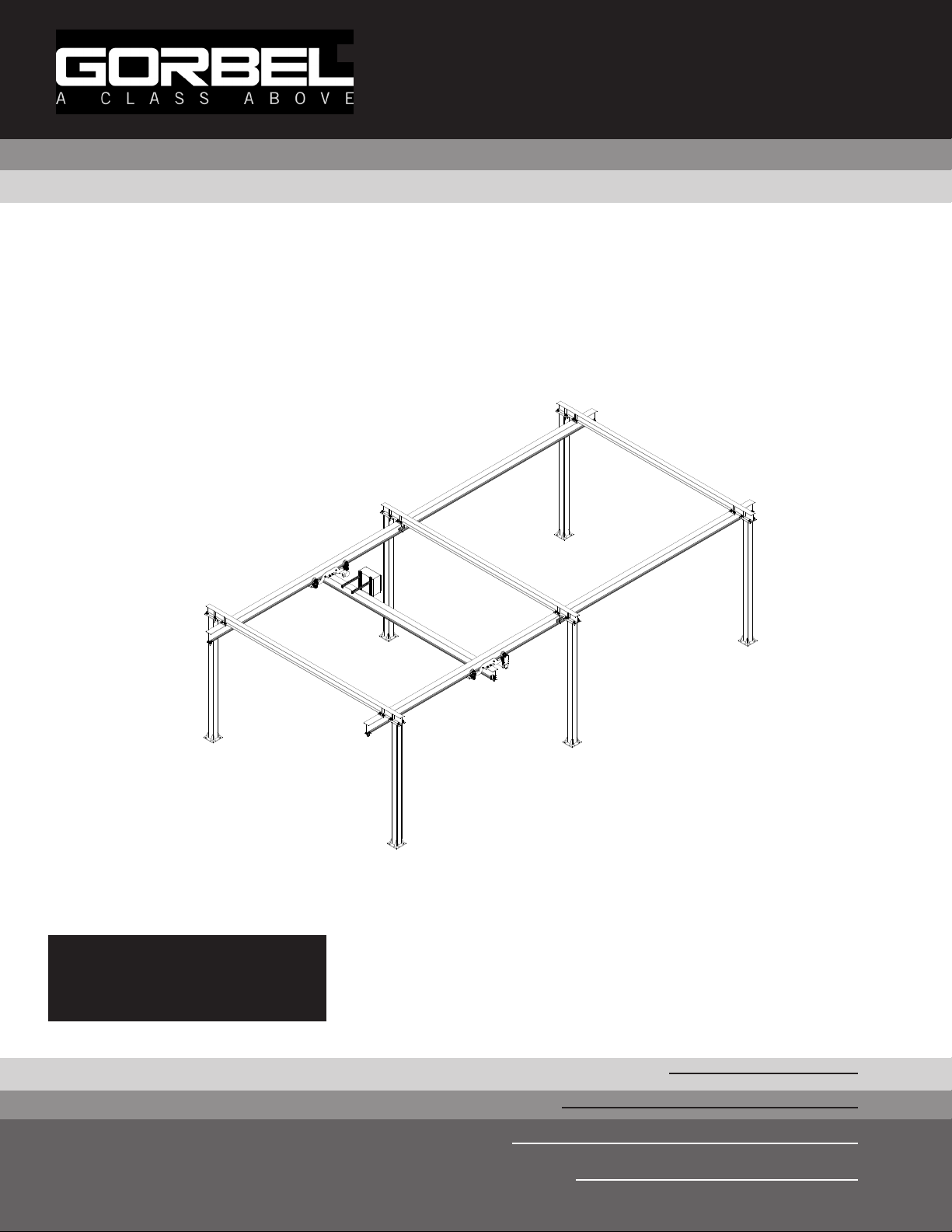
Totally Free Standing
Tarca® System
Gorbel® Customer Order No. / Serial No.
Gorbel® Dealer
Date
Month
Year
Page 2

This page intentionally left blank.
Page 3

TABLE OF CONTENTS
Introduction ............................................................................................................ 1
Installation
Step 1 - Pre-assembly ..........................................................................................................2
Step 2 - Column Weldment Installation ................................................................................3
Step 3 - Header Weldment Installation ................................................................................4
Step 4 - Runway Installation ............................................................................................. 5-8
Step 5 - Runway and Bridge End Stop Installation .......................................................... 8-9
Step 6 - Bridge and End Truck Installation .................................................................... 9-11
Step 7 - Carrier Installation ........................................................................................... 11-12
Step 8 - C-Track Festooning Installation (Optional) ..................................................... 13-15
Step 9 - Enclosure Mounting Detail (Pre-Assembled) ........................................................15
Step 10 - Bridge Girder Conduit Installation .........................................................................16
Step 11 - Motor Wiring .........................................................................................................17
Step 12 - Runway Conductor Bar Installation (Safe-Lec) .............................................. 18-19
Step 13 - Runway Conductor Bar Installation (SAFPOWRBAR®) ................................ 20-27
Step 14 - Sway Brace Installation (Optional) .......................................................................28
Step 15 - Final Steps ............................................................................................................29
Crane Operator Instructions .................................................................................30
General Safety Suggestions.................................................................................30
Limited Warranty ..................................................................................................31
Periodic Inspection and Lubrication Recommendations ................................. 33-36
Questions? Concerns? Comments? Please call (800) 821-0086 (US and Canada) or
(585) 924-6262 (outside US).
9/18 Rev. F
Page 4

This page intentionally left blank.
Page 5

INTRODUCTION
Thank you for choosing Gorbel® Tarca® Systems to solve your material handling needs. The innovative design and
heavy-duty construction of the Gorbel® Tarca® Systems will provide a superior quality product that will offer years
of long term value. The hoist weight allowance is 15% of the crane’s capacity (for example, a crane rated for 6000
pounds allows for a 6000-pound live load plus 900 pounds for the weight of the hoist). There is also an allowance
of 15% of the crane capacity for impact caused by hoist use. Gorbel® Tarca® Systems will provide many years of
dependable service by following the installation and maintenance procedures described herein.
Dimensions contained in this installation manual are for reference only and may differ for your particular
application. Please refer to the enclosed General Arrangement Drawing for actual dimensions.
Normal safety precautions prior to load testing: These include, but are not limited to:
• Checking for obstructions in crane travel.
• Checking that all bolts and threaded rods are tight and have lockwashers.
• Making sure that endstops are in place and functional (i.e. stopping rolling equipment from exiting rail).
• Making sure that festooning cannot be snagged or pinched, whether it is electric or pneumatic.
• For additional safety precautions, see page 30.
WARNING
Please read entire manual prior to starting installation.
WARNING
Gorbel Inc. assumes no responsibility for adequacy or integrity of the mounting surfaces or the structure that the
crane may be mounted to. Gorbel Inc. will not be liable for any loss, injury or damage to persons or property, nor
for damages of any kind, resulting from the failure or defective operation of any materials not supplied directly by
Gorbel Inc. Bracing systems, if used, must be approved by a local professional engineer.
WARNING
A minimum of a 6”-thick reinforced concrete floor is required. Gorbel, Inc., assumes no responsibility for adequacy or integrity of the mounting surface. Support assemblies are designed to AISC (American Institute of Steel
Construction) specifications. See pages 33-36 for maintenance schedule.
WARNING
Equipment described herein is not designed for, and should not be used for, lifting, supporting or transporting
humans. Failure to comply with any one of the limitations noted herein can result in serious bodily injury and/or
property damage. Check State and Local regulations for any additional requirements.
WARNING
Crane cannot be utilized as a ground: A separate ground conductor is required. For example, systems with 3 phase
power require three conductors plus one ground conductor.
WARNING
Reference the American Institute of Steel Construction (AISC) Manual of Steel Construction Specification
for Structural Joints using ASTM A325 or A490 Bolts, Installation, Pretensioned Joints, Calibrated Wrench
Pretensioning for the proper procedures to follow when using any torque tightening method.
9/18 Rev. F
1
Page 6
INSTALLATION
TIP: Packing list can be found in envelope attached to hardware box: General Arrangement
Drawing can be found inserted in this installation manual.
TIP: Recommended guidelines to help you determine anchor bolt size are supplied below
(anchor bolts are not included).
STEP 1 - PRE-ASSEMBLY
1.1 Check packing list to make sure correct quantity of parts is included.
1.2 Tools and materials (by others) typically needed to assemble crane are as follows:
• Mallet • Torque wrench
• Chalk line • Tape measure
• Hand tools • Ladders/man lifts
• Grout • Clamps (large C)
• Spud wrench • Leveling tools (transit, laser level, water level, etc.)
• Shop brush • Lifting device to lift heavy runways, bridges, headers
• Steel shims • Welder (if splices are welded)
• Large square • 3/4” anchor bolts (by others, see 1.3 for guidelines in
determining length)
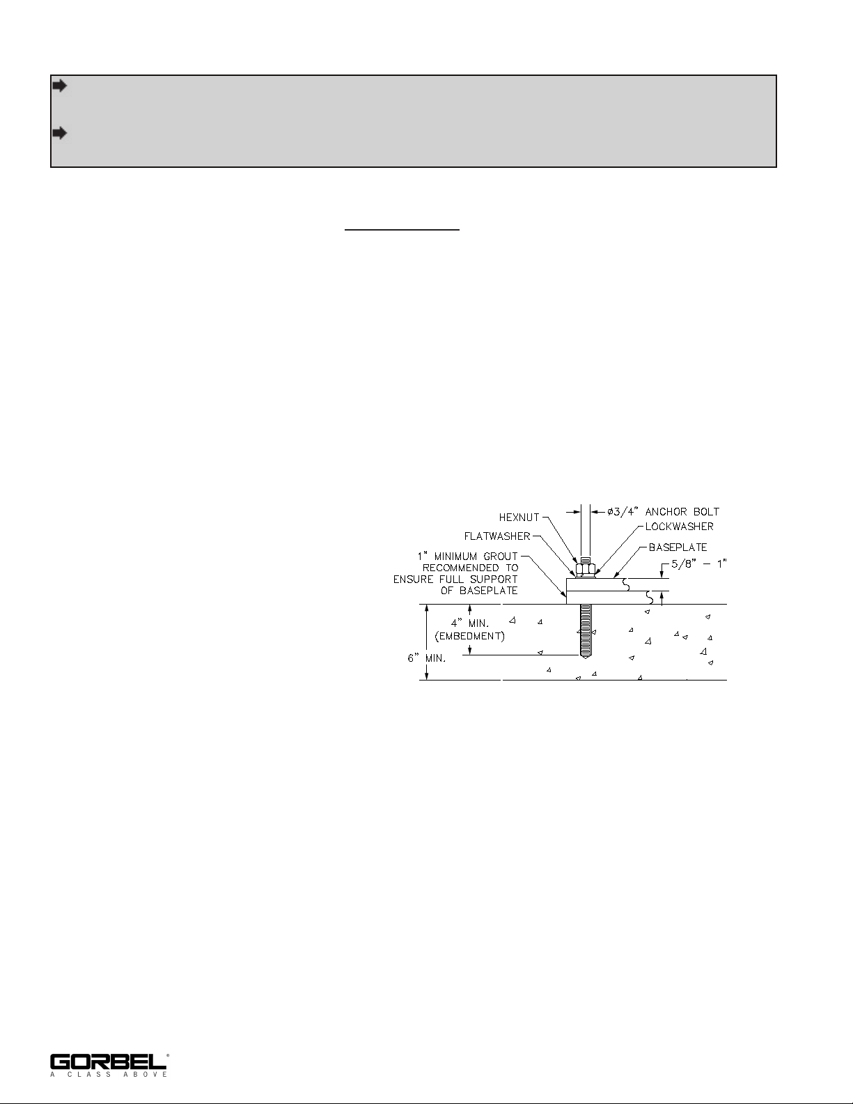
1.3 Recommended guidelines for determining bolt size and type:
Anchor bolts must:
• be 3/4” in diameter.
• be grade 5 or better.
• be embedded at least 4” into
floor, not to exceed 3/4 of floor
depth (diagram 1A).
• have minimum of two threads
Diagram 1A. Typical anchor bolt embedment.
above nut.
Note: A minimum 6”-thick reinforced concrete floor is required.
Note: Free Standing Patented Track Bridge Crane foundation requirements are based on
a minimum soil pressure of 2500# per square foot. Concrete should be a minimum of
3000# per square inch of compressive concrete. Columns should be centered on a two
foot by two foot square area that is free from cracks, seams and walls.
Note: Grout is required to ensure the base plate has full contact support to the floor/
footing. Shimming/leveling nuts under the base plate are acceptable methods that would
aid leveling of the columns prior to setting the columns on the grout bed (shimming/
leveling nuts by others). Grout must be a non-shrink, high compressive machinery type
grout.
Note: Chemical (epoxy) anchor bolts are recommended. Chemical anchors to withstand a
minimum of 4880# of pull our force.
2
9/18 Rev. F
Page 7
STEP 2 - COLUMN WELDMENT INSTALLATION
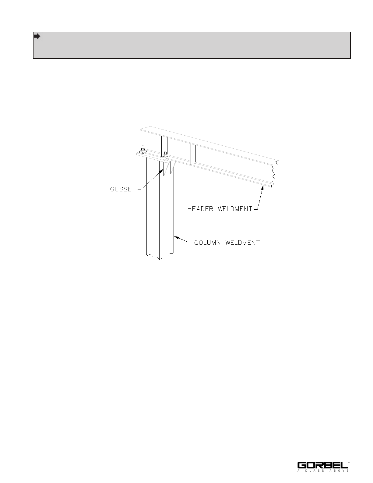
TIP: Be sure that column cap plate (top of column) is oriented in direction of header
weldment. Column gussets must face inward towards bridge and runway as
shown.
2.1 Lay out and mark on floor exact position of column weldments prior to proceeding with
installation (refer to enclosed General Arrangement Drawing for recommended
dimensions and column weldment location).
2.2 Position first column weldment in place. Orient column cap plate (top of column) as shown
in diagram 2A.
Diagram 2A. Orienting column top plate.
2.3 While supporting column weldment, drill holes in concrete floor using pre-drilled holes in
column weldment base as a guide (use drill bit size recommended by anchor bolt
manufacturer). Vacuum or brush away cement dust.
2.4 Install anchor bolts (not included) and hardware according to manufacturer’s installation
directions and requirements.
2.5 Check to see if column weldment is plumb. If column weldment is not plumb, loosen
anchor bolt nuts and place steel shims (if required, not included) then grout (not included)
under base of column weldment until plumb. After column weldment is plumb, tighten all
nuts (see diagram 1A, page 2).
2.6 Install remaining column weldments (repeat Step 2.2 through 2.5).
9/18 Rev. F
3
Page 8
STEP 3 - HEADER WELDMENT INSTALLATION
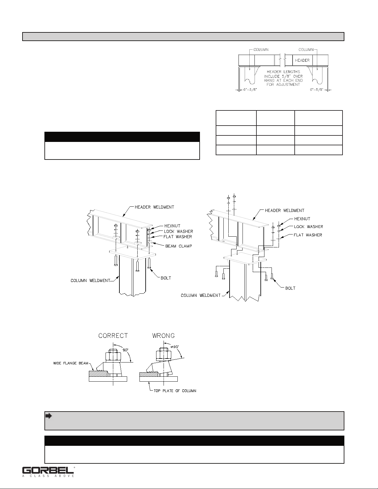
3.1 Lift and position header weldment onto two secured
column weldments (refer to enclosed General
Arrangement Drawing for recommended dimensions
and header weldment location). Using beam clamps
(depending on design) and hardware provided, attach
header weldment to column weldment.
Diagram 3A. Header length.
3.2 Tighten hardware. Refer to chart 3A for proper
torque.
WARNING
There must be a minimum of two threads
showing at the end of the bolt.
3.3 Install remaining header weldments (repeat Steps
3.1 through 3.2).
BEAM
CLAMP SIZE
5/8” 109 ft.-lbs. 12.3 kips
3/4” 210 ft.-lbs. 19.8 kips
1” 355 ft.-lbs. 25 kips
Chart 3A. Beam Clamp Torque Chart.
TORQUE
MINIMUM BOLT
PRETENSION
Beam Clamp Connection
Diagram 3B. Installing header weldments.
Diagram 3C. Beam Clamp Installation.
Direct Bolt Connection
TIP: 10” tall, wide flange headers with 5/8” hardware require a shim (supplied) to
obtain the correct beam clamp tail length to match the header flange thickness.
WARNING
If shimming column, shim must be located between floor and baseplate. Shims must not
be located at top of column.
4
9/18 Rev. F
Page 9

STEP 4 - RUNWAY INSTALLATION
Runways to Header Weldment Connections
4.1 Suspend runway section under installed support structure (refer to enclosed General
Arrangement Drawing for recommended dimensions and runway location).
TIP: Runway to be centered under gussets (diagram 4A).
4.2 Using beam clamps (depending on design) and hardware provided, attach runway section
to header weldment, as shown in diagram 4A. See chart 3A, page 4, for torque charts.
WARNING
If shimming runway, shim must be located between washer plate and top of runway.
Beam Clamp Connection
Diagram 4A. Attaching runway to header weldment.
Direct Bolt Connection
4.3 Check to make sure that runway is level
(within +/-1/4”) and parallel to opposite
runway (within +/-3/16”) over any span.
WARNING
Do not deviate from the bridge “span”
dimension shown on the General
Arrangement drawing. Bridge “span” is
the distance (+/- 3/16”) between runways
(centerline to centerline).
4.4 Tighten hardware (chart 3A, page 4), for
Diagram 4B. Track Perpendicularity.
proper torque rating.
WARNING
There must be a minimum of two threads showing at the end of the bolt.
4.5 If you DO NOT have additional runways to install, proceed to Step 5.1, on page 8;
otherwise proceed to Step 4.6 on page 6.
9/18 Rev. F
5
Page 10
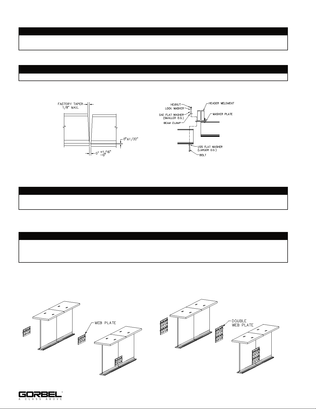
Splice Joint Instructions
WARNING
Reference the General Arrangement Drawing for splice locations. It will be necessary to install
adjacent runways at the same time.
4.6 Bring the ends of the track sections together as close as possible (diagram 4C).
WARNING
If shimming runway, shim must be located between washer plate and top of runway.
4.7 Align holes in washer plate with the slots in the top flange of the rail. Tighten beam clamp
hardware. This will help align the top flange portion of track sections (diagram 4D).
Diagram 4C. Rail Alignment.
Diagram 4D. Attaching header to top flange.
4.8 Place web splice plate(s) on each side of web section. Align plate as shown (diagrams
4E and 4F for welded splice or diagrams 4H and 4J for bolted splice).
WARNING
Track sections and web plate need to be carefully aligned before field welding of plates to
allow smooth transition between sections.
4.9 Web splice plates to be welded in accordance with American Welding Society (AWS)
specification D1.1 using E70xx electrodes (diagram 4G).
WARNING
If welding of lower track is desired (not required), different electrodes are required for mild steel
vs. hardened steel. E7018 is used for mild steel only (web and top flange). E11018 must be
used for hard steel and may also be used for mild steel.
4.10 Check to see that the transition from one track to the other is smooth: no raised areas to
inhibit carrier or end truck operation (diagram 4C).
4.11 For additional runways repeat Steps 4.6 through 4.10.
Diagram 4E. Welded splice (4200-4600 Tarca® beam).
Diagram 4F. Welded splice (5000 & Larger Tarca® beam).
6
9/18 Rev. F
Page 11
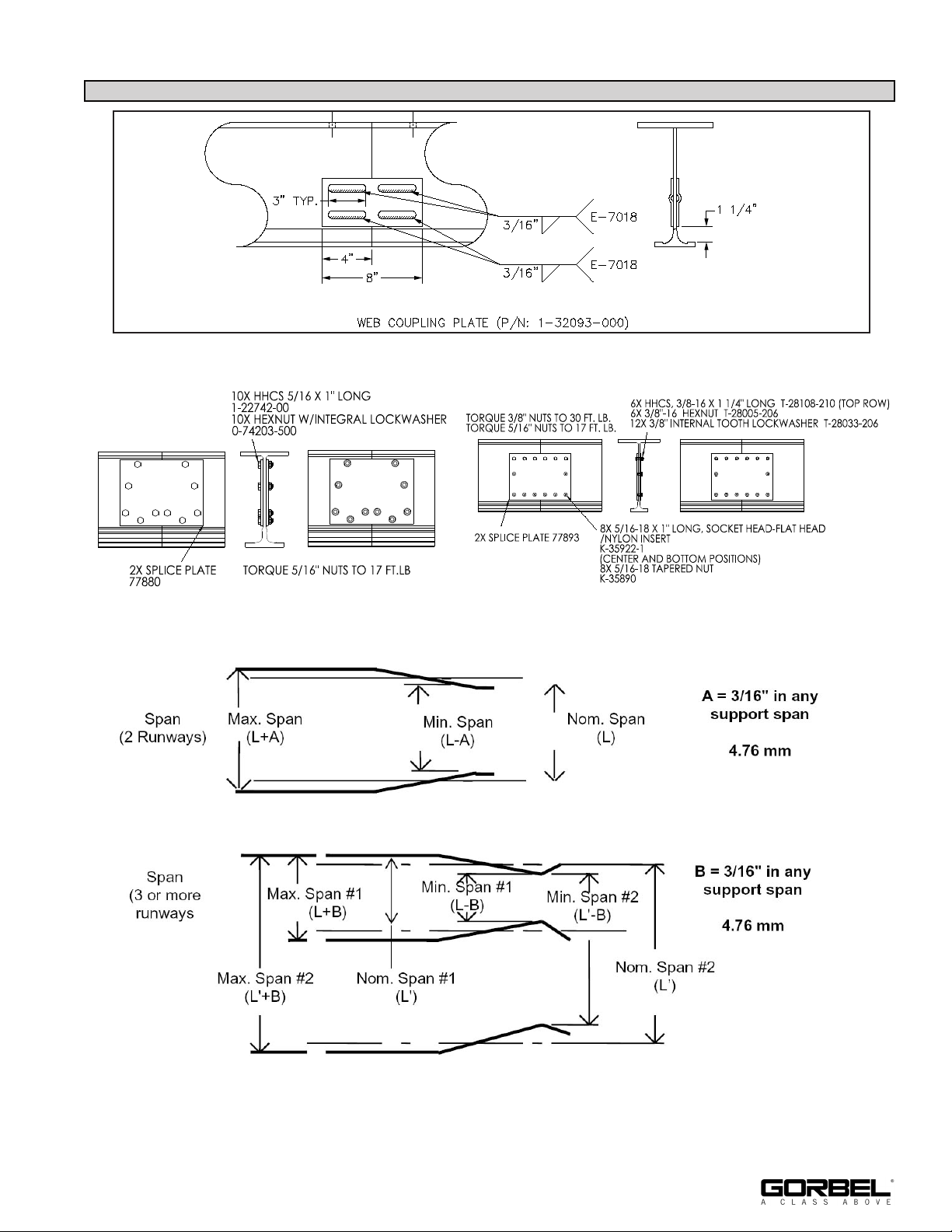
STEP 4 - RUNWAY INSTALLATION (CONTINUED)
Diagram 4G. Splicing Runways together.
Diagram 4H. Bolted splice (4200 - 4600 Tarca® beam).
Diagram 4J. Bolted splice (5000 and larger Tarca® beam).
9/18 Rev. F
Diagram 4K. Runway alignment tolerance.
7
Page 12
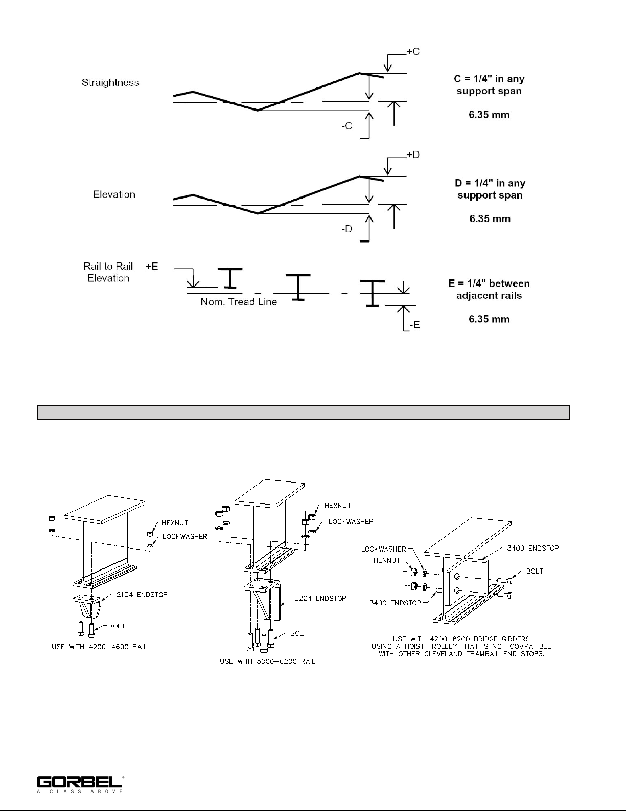
Diagram 4K (Continued). Runway alignment tolerance.
STEP 5 - RUNWAY AND BRIDGE END STOP INSTALLATION
5.1 End stops are required and must be installed at the ends of the carrier or trolley travel and
at the end of crane travel on runways (diagram 5A).
Diagram 5A. End stop.
8
9/18 Rev. F
Page 13
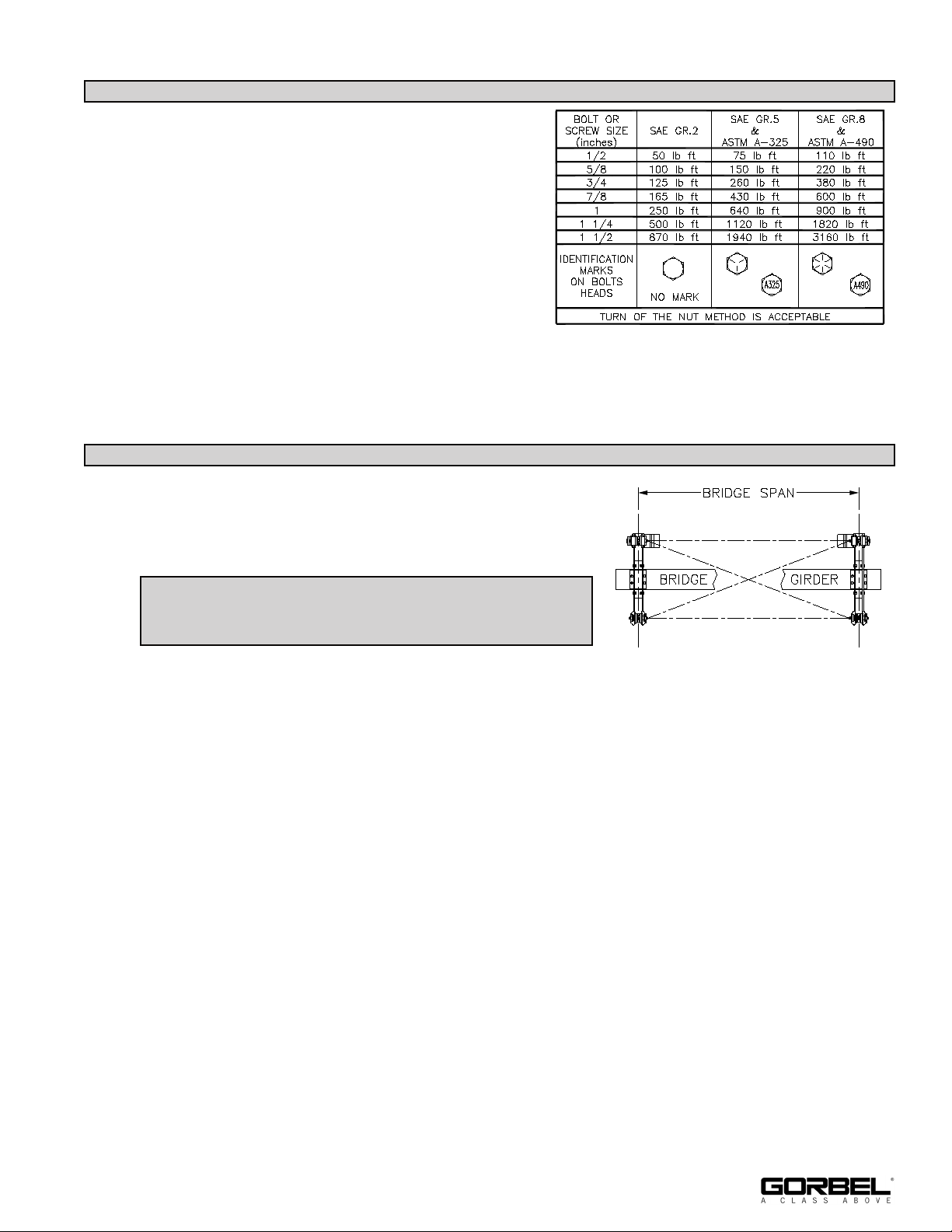
STEP 5 - RUNWAY AND BRIDGE END STOP INSTALLATION (CONTINUED)
5.2 The standard end stops are for normal
applications where contacts with end stops are
infrequent and travel is at slow speed.
5.3 When service conditions are such that the
carrier, trolley, or crane will contact the end stop
frequently or at high speed, spring bumpers or
other energy absorbing type end stops are
available and should be used. For their
application and detail contact our Inside Sales
Chart 5A. Torque Chart.
Department.
STEP 6 - BRIDGE AND END TRUCK INSTALLATION
FIRST STEPS:
6.1 Prior to adding bridge, wipe rail tread with a clean, dry
cloth to remove grit or debris that may have collected
during shipping, storage, or installation.
If customer is supplying bridge, go to step 6.2. If
endtrucks and bridge are ordered together, start at
step 6.9.
6.2 Lay bridge girder on floor. Stabilize the girder so that it
Diagram 6A.
cannot tip over.
6.3 Place endtrucks on top flange of girder and orient them so that the motors will be in the
desired location (diagram 6A - solid lines indicate standard motor position). Center the
endtruck to bridge connection bolt pattern on the girder. Make sure that the bridge span
exactly matches the distance between runway centerlines. Also confirm that the endtrucks
are square to the girder by matching diagonal measurements.
6.4 Transpose the bolt pattern from endtruck to bridge girder. Match mark endtrucks and
bridge.
6.5 Drill bolt holes (Ø 49/64”).
6.6 Bolt endtrucks into place. Confirm that the bridge span is correct and endtrucks are
square.
9/18 Rev. F
9
Page 14
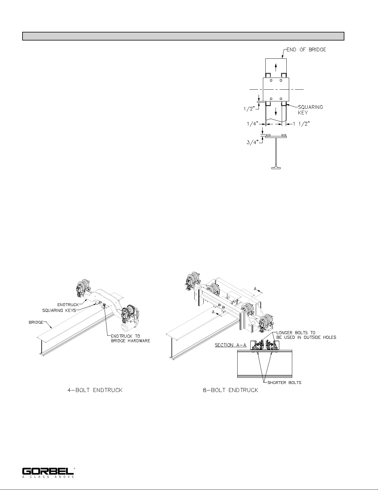
STEP 6 - BRIDGE AND END TRUCK INSTALLATION (CONTINUED)
6.7 Weld squaring blocks into place according to
diagram 6B.
• All welds to be 3/16” fillet.
• Weld both sides of key, starting 1/2” from
endtruck channel.
• Weld in direction away from channel, as shown by
arrows in diagram 6B.
• Weld end of key.
6.8 Remove end trucks from girder.
6.9 Place end trucks onto runway. Drive head motors
should face inward and be located across from each
other as indicated in diagram 6A, page 9.
Diagram 6B.
6.10 Lift bridge into place. The end trucks and bridge are
match marked. Make sure that the markings on the bridge and end truck correspond. The
bridge girder should be snug to the end truck. The squaring keys will fit around the outside
of the end truck body.
6.11 Make sure all runway endstops have been properly installed.
6.12 Attach the end trucks to the bridge with the end truck to bridge hardware provided
(diagram 6C). Tighten hardware according to chart 5A, page 9.
Diagram 6C.
10
9/18 Rev. F
Page 15
STEP 6 - BRIDGE AND END TRUCK INSTALLATION (CONTINUED)
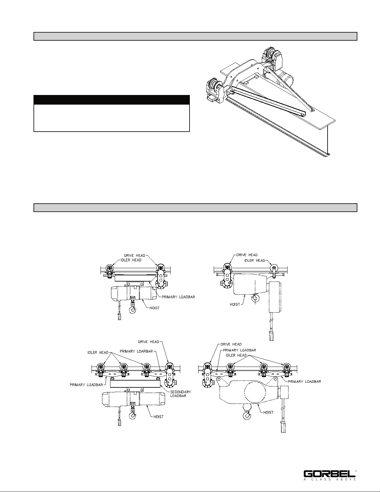
6.13 If equipped, attach bracing to endtruck and
bridge girder as shown in diagram 6D.
6.14 Tighten endtruck and bridge hardware.
WARNING
Diagram 6D is for reference only. Your actual
end truck may vary, but bracing basics are the
same.
Diagram 6D.
STEP 7 - CARRIER INSTALLATION
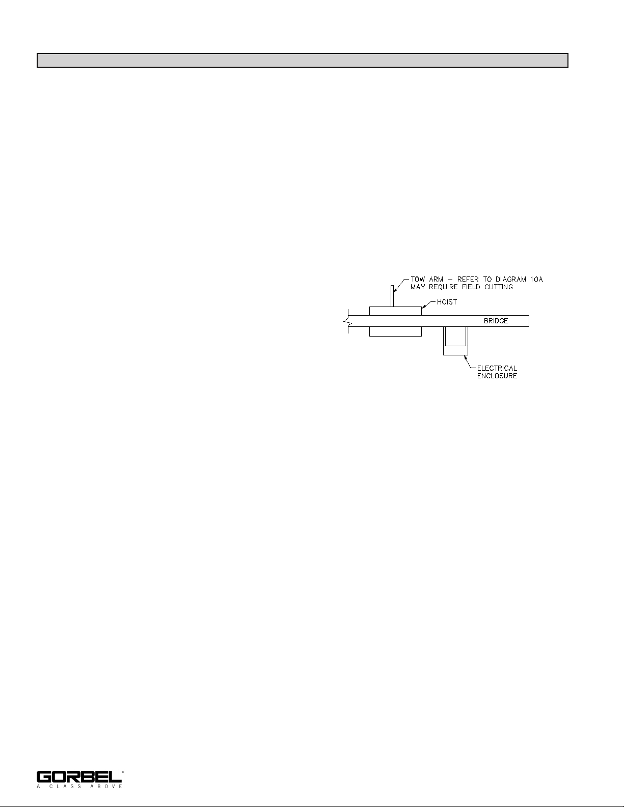
7.1 If ordered, Gorbel will provide one of the following motor driven carriers:
Motor Driven Carriers With Electric Hoists (Hoists by Others) - WT and WS Series
Diagram 7B. WS
Diagram 7A. WT Carrier (2 Head).
Carrier (2 Head).
9/18 Rev. F
Diagram 7C. WT Carrier (4 Head).
Diagram 7D. WS Carrier (4
Head).
11
Page 16
STEP 7 - CARRIER INSTALLATION (CONTINUED)
7.2 Clean bridge track tread surface with a clean, dry cloth (do not use any kind of cleaning
solution) to remove grit or debris that may have collected during shipping, storage, or
installation.
7.3 Be sure end stop is installed opposite the end of bridge from the end carrier is loaded into.
7.4 If possible install carrier by inserting onto end of bridge girder.
7.5 If end clearance prohibits sliding the carrier onto track, drive and idler heads have to be
split and reassembled on the bridge girder. If this is the case, both end stops should be
installed. Single piece frame type idler heads can be installed on the track by removing
the wheels.
7.6 If a tow arm is being utilized assemble the
tow arm weldment to the carrier on the
festooning side of the bridge (diagram 7E).
7.7 Install remaining endstop on the bridge
girder (Step 6, on page 9).
7.8 Make sure all connections are secure using
the proper hardware and torque to
Diagram 7E. Standard tow arm orientation (top view).
specification.
7.9 If hoist and carrier were not pre-assembled, assemble trolley to hoist per manufacturer’s
assembly instructions.
12
9/18 Rev. F
Page 17
STEP 8A - WEB MOUNT C-TRACK FESTOONING INSTALLATION (OPTIONAL)
WARNING
If pre-wired connections exist, orient the male end of the cable towards the electrical enclosure
of the bridge prior to assembling cables into C-Track.
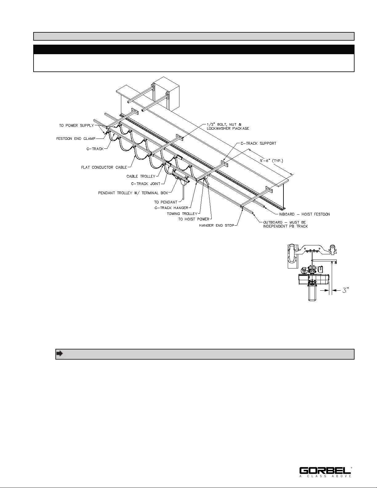
Diagram 8A. C-Track festooning.
8A.1 Install first cross arm support piece to the pre-drilled web holes
using the hardware provided. Remaining cross arm supports to be
installed at 5’-6” increments along web of rail.
8A.2 Bolt track hangers loosely to cross arm supports, while sliding
each 10’-0” long section of C-Track into place. Start at one end of
system.
Diagram 8B. End view.
8A.3 Install track joints as required. They will support the adjacent
sections of track. After all track sections and hangers are in place, secure all fasteners.
TIP: Last track section may need to be field cut to length.
8A.4 Install festoon end clamp to one end of system.
8A.5 Install cable trolleys into track system. If it is convenient, cables may be installed into
trolleys on the floor. If loops extend past the hoist hook at its highest position, the loops
should be shortened.
8A.6 Install the towing trolley or pendant trolley. Alternate method would be to install all trolleys
and cable into one length of C-Track and lift into place.
8A.7 Install the hanger endstop into open end of C-Track.
9/18 Rev. F
13
Page 18
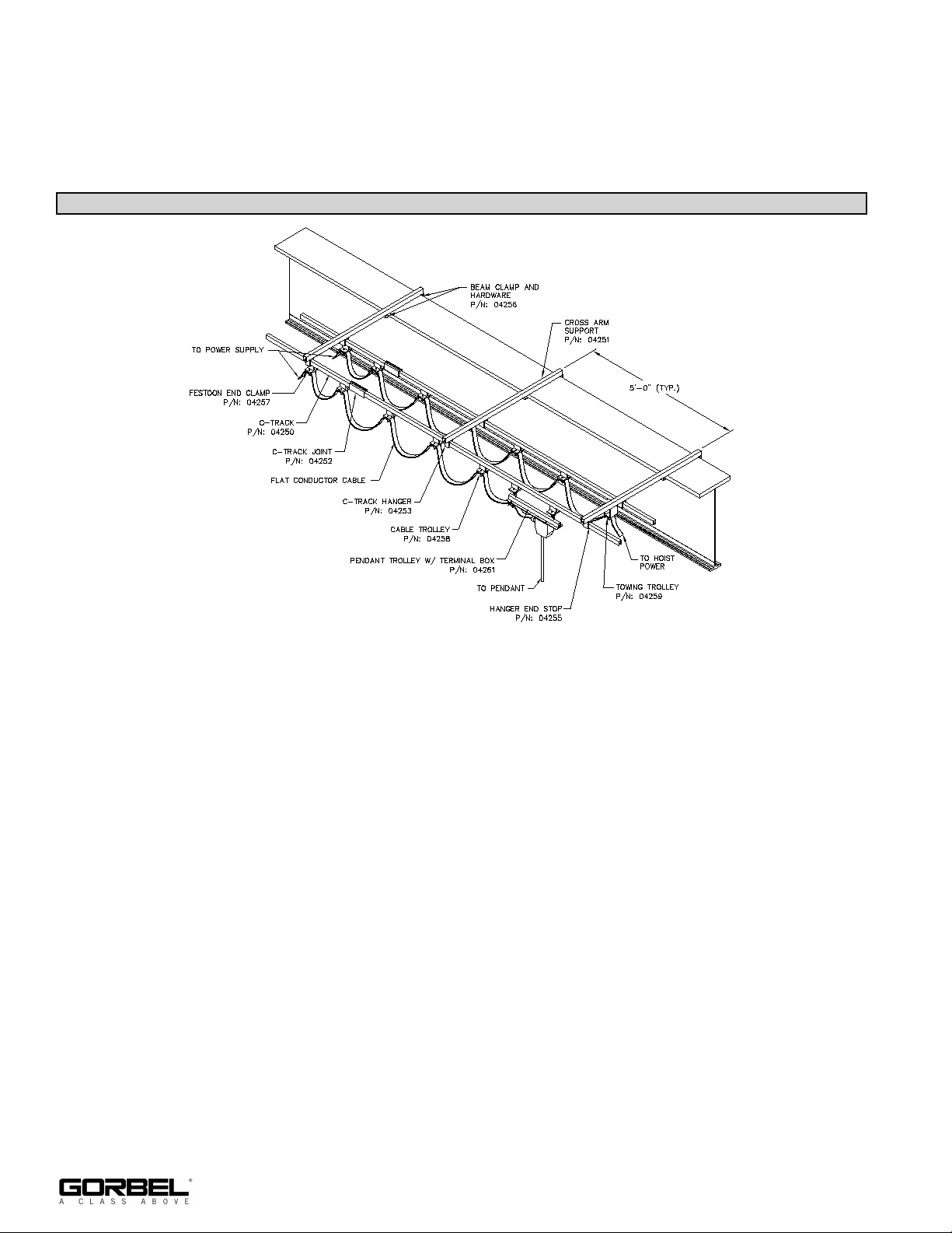
8A.8 The selected cable connectors can be installed in the appropriate junction boxes and the
cable connected.
8A.9 Repeat the above stops as necessary for second C-track.
STEP 8B - TOP FLANGE C-TRACK FESTOONING INSTALLATION (OPTIONAL)
Diagram 8C. Top Flange C-Track Festooning.
8B.1 Divide total length of beam by 5’-0”. This will gaive equal number of spaces of cross arm
support brackets. The remainder should be divided equally among each end.
8B.2 Measure the distance from the end of Tarca® track from Step 8B.1 above and install first
cross arm support piece. Secure on each side of top flange with beam clamp and
hardware. Remaining cross arm supports to be installed at 5’-0” increments along top
flange of rail.
8B.3 Bolt track hangers loosely to cross arm supports, while sliding each 10’-0” long section of
C-Track into place. Start at one end of system.
8B.4 Install track joints as required. They will support the adjacent sections of track. After all
track sections and hangers are in place, secure all fasteners.
8B.5 Install festoon end clamp and hanger endstop to one end of system.
8B.6 Install cable trolleys into track system. If it is convenient, cables may be installed into
trolleys on the floor, establishing correct size of loops and tie wrap cables as needed.
14
9/18 Rev. F
Page 19
8B.7 Install the towing trolley or pendant trolley. Alternate method would be to install all trolleys
and cable into one length of C-Track and lift into place.
8B.8 Install second hanger endstop into open end of C-Track.
8B.9 The selected cable connectors can be installed in the appropriate junction boxes anmd the
cable connected.
8B.10 Repeat the above steps as necessary for second C-Track.
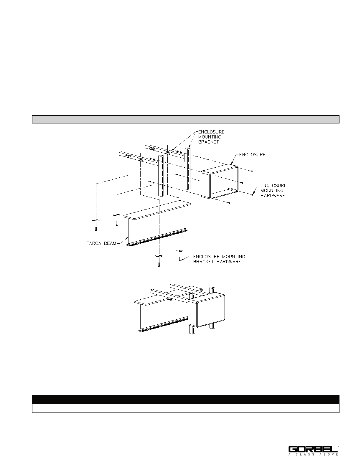
STEP 9 - ENCLOSURE MOUNTING DETAIL (PRE-ASSEMBLED)
Diagram 9A. Enclosure Assembly.
9.1 Clamp enclosure mounting bracket to top flange of beam using enclosure mounting
bracket hardware provided.
9.2 Attach enclosure box to face of brackets using hardware provided.
WARNING
Verify panel and mounting brackets are positioned to avoid hoist interference.
9/18 Rev. F
15
Page 20
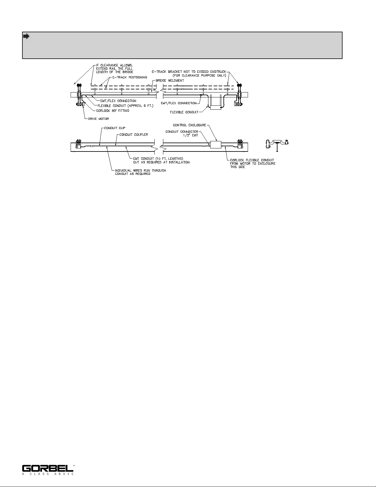
STEP 10 - BRIDGE GIRDER CONDUIT INSTALLATION
TIP: If requested, Gorbel can install the rigid conduit on the bridge girder. Installer will be
responsible for attaching control enclosure (Step 9) and making all flexible conduit
connections. Reference Step 11 for motor wiring.
Diagram 10A. Bridge conduit wiring diagram.
10.1 If not already installed by Gorbel, secure EMT conduit below top flange of girder avoiding
trolley interference. Conduit is shipped in 10 ft. lengths to be cut as needed.
10.2 Flexible conduit to be mated to EMT conduit with connectors provided.
10.3 Flexible conduit to be routed as shown (Diagram 10A) into either side of control
enclosure.
10.4 NOTE: If splicing of the wire is necessary, a junction box will be required. An EMT / flex
connection can be used with a continuous length of wire from enclosure to motor.
16
9/18 Rev. F
Page 21
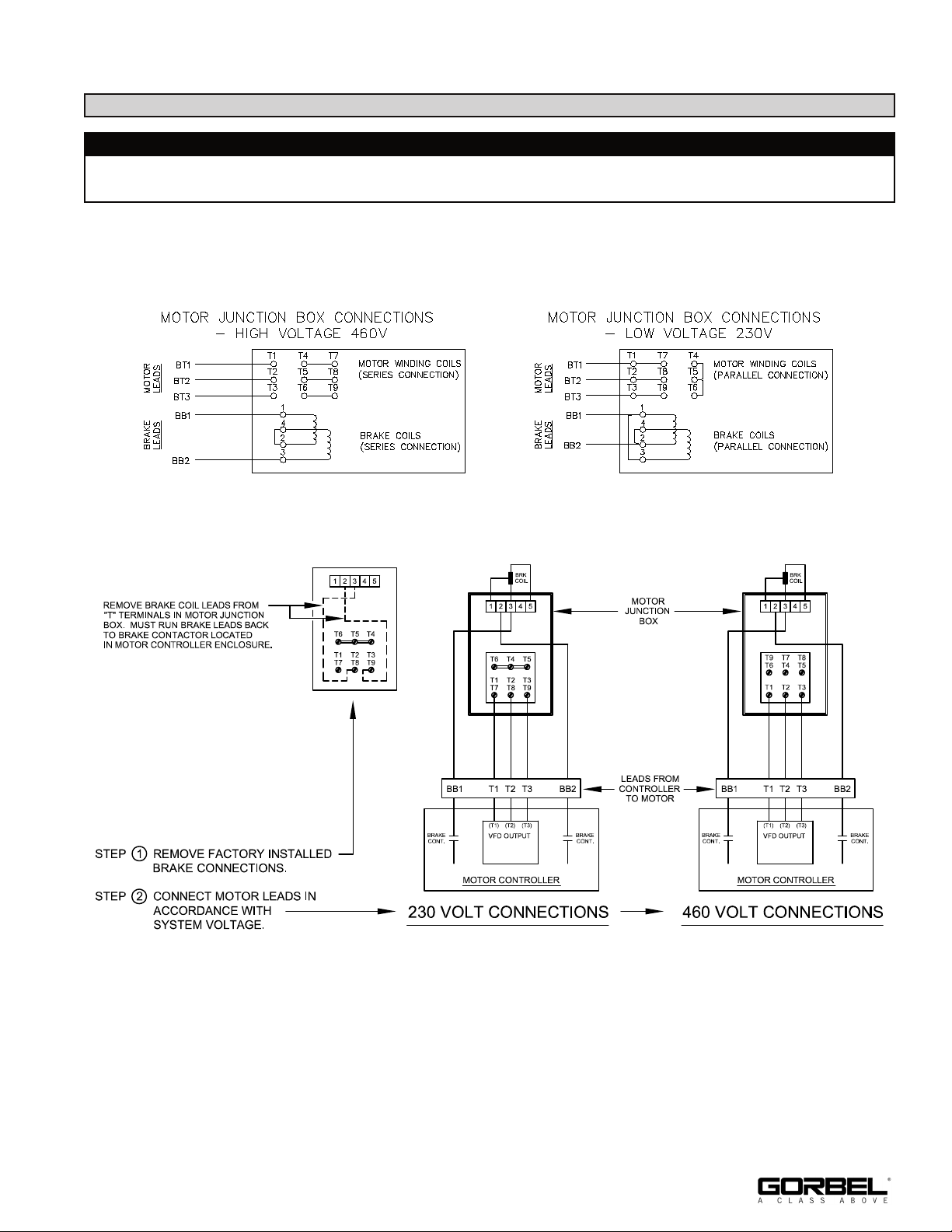
STEP 11 - MOTOR WIRING
NOTE: Brake control must be on separate circuit.
WARNING
Typical schematics shown for motors that are reconnectable for high or low voltage. Refer to
supplemental drawings and J-box on motor for your specific design.
11.1 Wire according to appropriate figure below. For SEW motors refer to diagram 11C.
11.2 Motor and brake voltages must be identical.
Diagram 11A.
Diagram 11B.
9/18 Rev. F
Diagram 11C.
17
Page 22
STEP 12 - RUNWAY CONDUCTOR BAR INSTALLATION (SAFE-LEC)
(for Safpowrbar® Runway Conductor Bar Installation, proceed to Step 13, page 20)
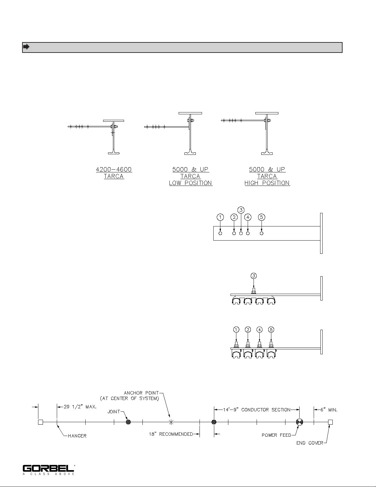
TIP: Install brackets inboard of runway closest to enclosure (diagram 12H, page 19).
12.1 Bolt hanger brackets to web of runway with 1/2” hardware. For 5000 series and larger
Tarca® rail, the bracket position is based on wheel size. Brackets will be mounted in
“high” or “low” positions. Low position is used when carriers have 5” diameter or smaller
wheels. High position is used when carriers have 7” or smaller, but greater than 5”
diameter wheels. Refer to diagram 12A.
Diagram 12A. Conductor bar mounting bracket.
12.2 The bracket has hole patterns as shown
in Diagram 12B. Bolt conductor bar
hangers to brackets according to
Diagram 12C.
12.3 Each system requires the use of anchor
clamps. The anchor clamps will replace one
regular conductor bar hanger and serve to
prevent the bars from sliding back and forth
on the runways. These anchor clamps
should be placed in the center of the
conductor bar system (Diagram 12D).
Diagram 12B.
Four bar hanger.
Anchor clamps for 4-bar set-up.
Diagram 12C.
Diagram 12D. Typical conductor bar.
18
9/18 Rev. F
Page 23
STEP 12 - RUNWAY CONDUCTOR BAR INSTALLATION (SAFE-LEC) (CONT.)
(for Safpowrbar® Runway Conductor Bar Installation, proceed to Step 13, page 20)
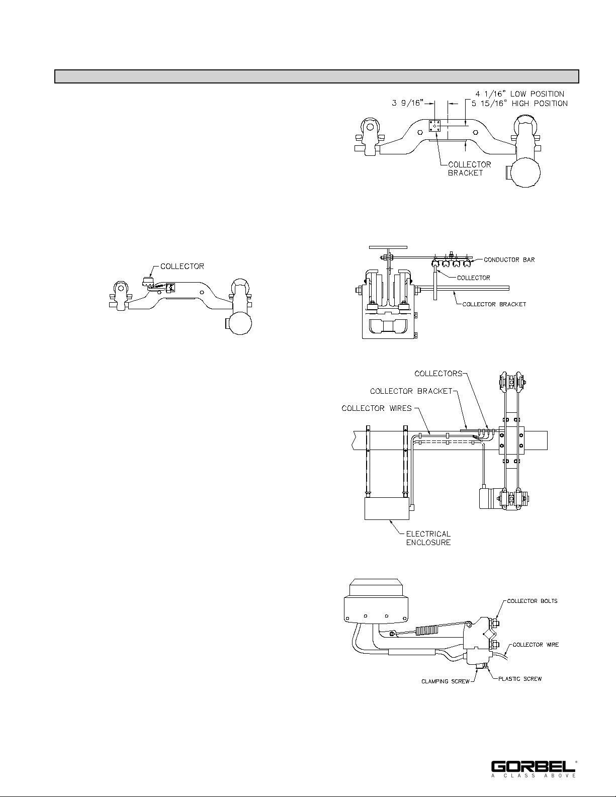
12.4 Attach collector bracket to side of endtruck
according to Diagram 12E. Bracket may be
tack welded or bolted into place. If bolting,
locate the bracket as shown, mark the hole
locations, and drill three Ø3/8” holes.
12.5 Slide the first collector onto the collector
Diagram 12E.
bracket as shown in Diagram 12F.
12.6 Position collector so it lines up with the first conductor bar (Diagram 12G) and tighten
collector bolts to clamp it into place.
Diagram 12F.
Diagram 12G.
12.7 Run a minimum of 4COND 12AWG
SO(W) (recommended) cable from
collectors to electrical enclosure as
shown (diagram 12H).
12.8 Strip the end of the collector wire and
insert into the collector as shown in
Diagram 12J.
12.9 Clamp the wire with the two screws. The
plastic screw should tighten down on the
wire’s insulation. When tightening the
clamping screw there will be some
resistance. Keep tightening until the wire
is clamped firmly in place.
12.10 Repeat steps 12.5 through 12.9 for the
remaining collectors.
9/18 Rev. F
Diagram 12J.
Diagram 12H.
19
Page 24
STEP 13 - RUNWAY CONDUCTOR BAR INSTALLATION (SAFPOWRBAR®)
(for Safe-Lec Runway Conductor Bar Installation, go back to Step 12, page 18)
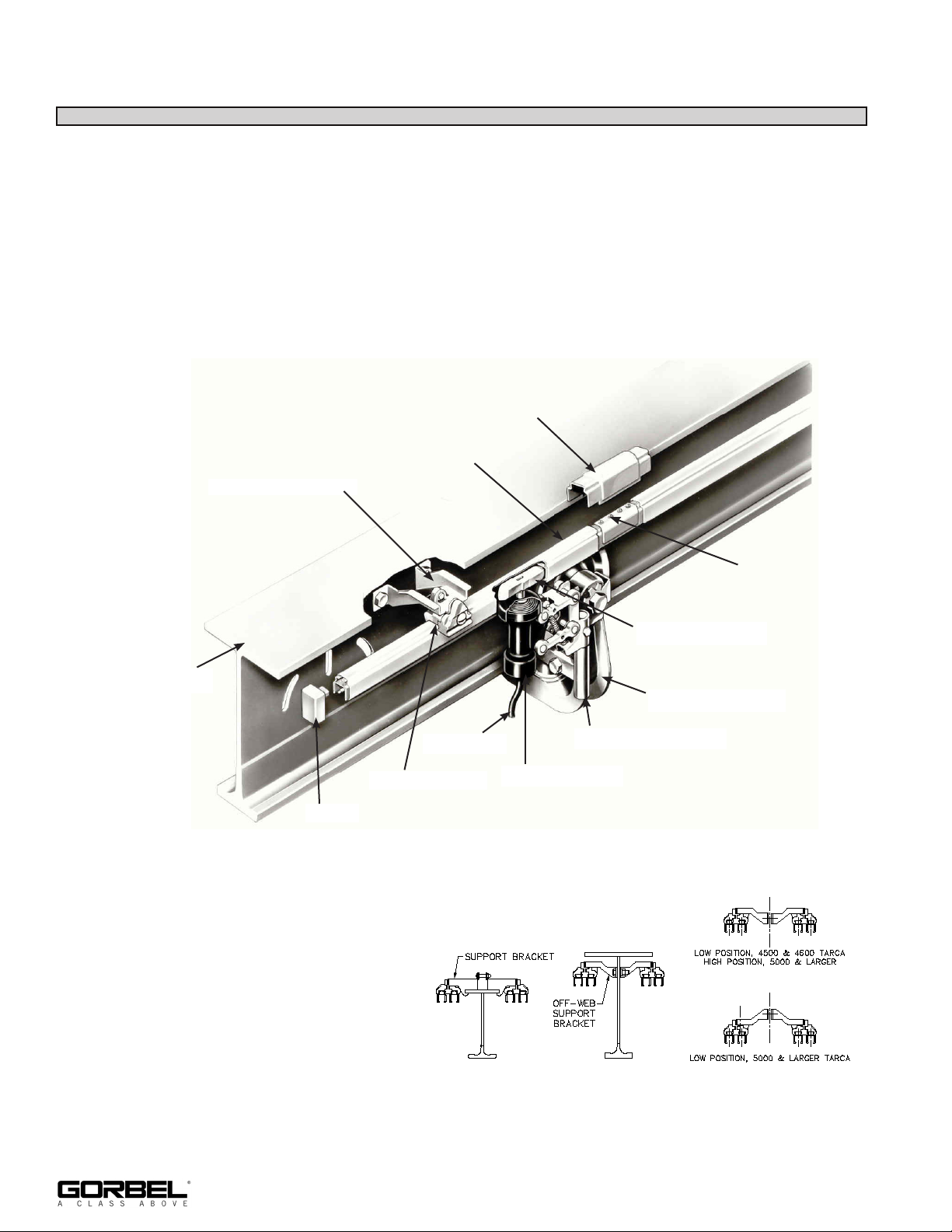
Mounting Insulating Cover on Bar
13.1 Under normal circumstances the insulating cover will be shipped mounted on the bar, but
in case removal or replacement is necessary, the following procedure is suggested.
13.2 Starting the cover 2-1/8” down from the end of the bar and flat on top of the bar, mold the
cover down over the bar and work the lips of the cover over the legs of the bar. The
conductor bar is furnished in lengths of 21’-0” and the cover is furnished in lengths of
20’-7-3/4” which allows 2-1/8” of the bar to extend beyond the cover at each end. The
cover fits tightly on the bar and does not require any additional clamps to hold it in place.
Coupling Cover
SAFPOWRBAR®
Offweb Support Bracket
Tarca® Beam
Support Insulator
End Cap
Conductor Bar Mounting and Brackets
13.3 The conductor bar is held on by
insulators which are attached to
mounting brackets (diagram 13A).
There are two types of mounting
brackets as shown in diagram
13B.
Collector Lead
Diagram 13A.
Coupling
Collector Shoe
Idler Head
Collector Bracket
Type ST Collector
20
Diagram 13B.
9/18 Rev. F
Page 25
STEP 13 - RUNWAY CONDUCTOR BAR INSTALLATION (SAFPOWRBAR®) (CONT.)
(for Safe-Lec Runway Conductor Bar Installation, go back to Step 12, page 18)
Mounting Conductor Bar and Brackets (Continued)
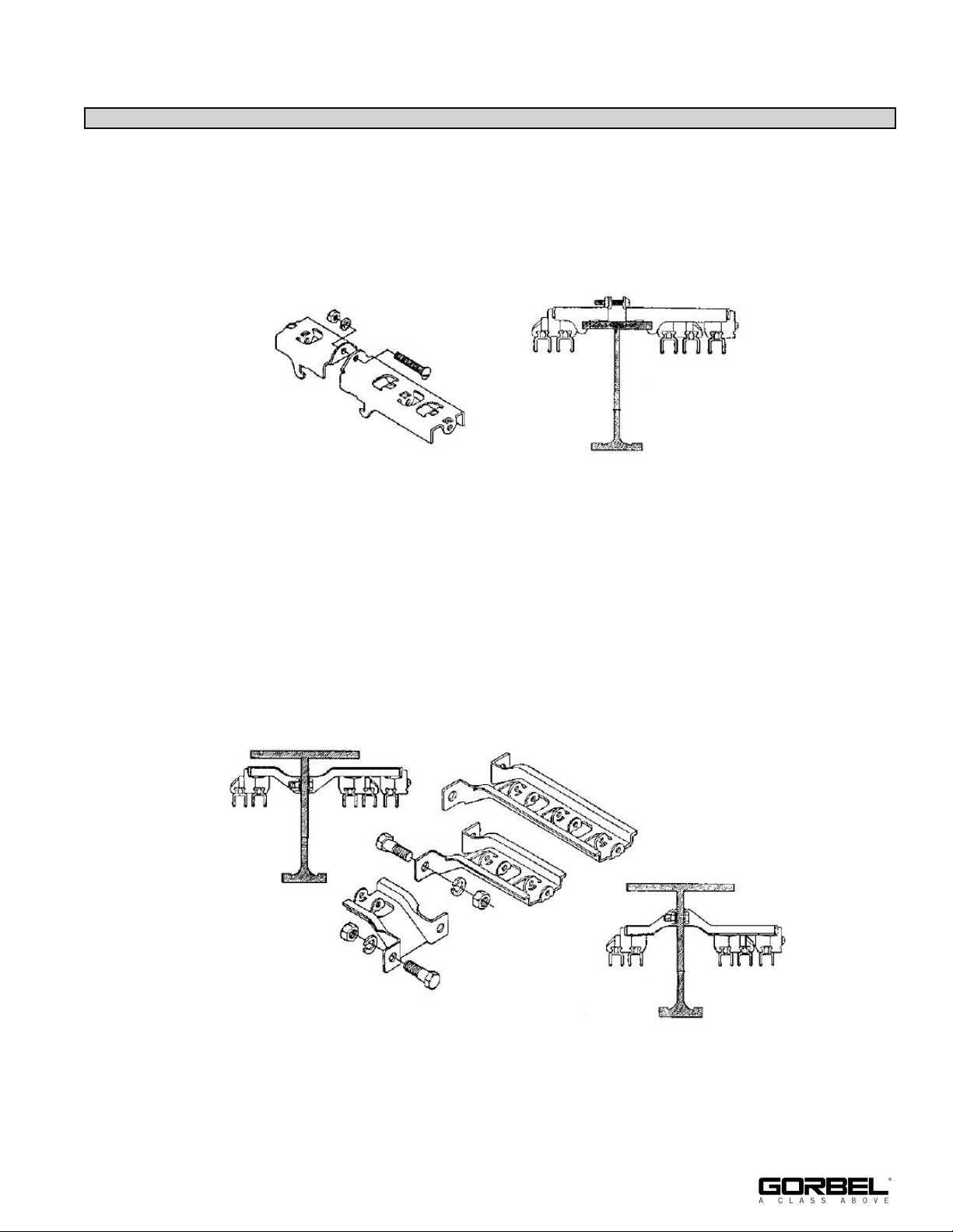
• For 8” and 8-1/2” Tarca® track with wheels 5” diameter or less, the conductor bar
mounting brackets are mounted across the top flange of the track. Attach brackets by
fitting the notched ends over the top flange of the beam and securing with the provided
screw, lockwasher, and hexnut (diagram 13C). Note: Bracket configuration shown
may be different than yours.
Diagram 13C.
• For Tarca® track 10” and taller, the conductor bar mounting bracket is mounted to the
pre-drilled Tarca® web holes. Attach brackets by inserting provided bolts through the
near side bracket, through the holes in the beam web, and through the far side
bracket, securing brackets with lockwashers and hexnuts (diagram 13D). Note:
Bracket configuration shown may be different than yours.
Based on wheel size, brackets will be mounted in “high” (8” from the rail tread to the
underside of the conductor bar) or “low” (6-3/16” from the rail tread to the underside of
the conductor bar) positions. Low position is used when carriers have 5” diameter or
smaller wheels. High position is used when carriers have 7” or smaller, but greater
than 5” diameter wheels (5000 series and larger Tarca® rail only).
Diagram 13D.
13.4 The standard spacing for the mounting brackets on straight rail sections (web and flange
mounted) is 5’-6”.
*Light rails typically have holes drilled every 33”; it is only necessary to use every other
set of holes.
9/18 Rev. F
21
Page 26
STEP 13 - RUNWAY CONDUCTOR BAR INSTALLATION (SAFPOWRBAR®) (CONT.)
(for Safe-Lec Runway Conductor Bar Installation, go back to Step 12, page 18)
Mounting Conductor Bar and Brackets (Continued)
Note: The standard mounting for SAFPOWRBAR® conductor bars to assure proper
clearance at endtrucks is to mount two bars on each side of the runway rail. For other
than its standard location, and on low headroom cranes, or when more than four
conductor bars are required on a runway, contact Gorbel® Customer Service for location
data.
*For SL412 and SL416 endtrucks, the standard configuration is three bars on the inside
of the runway and one bar on the outside.
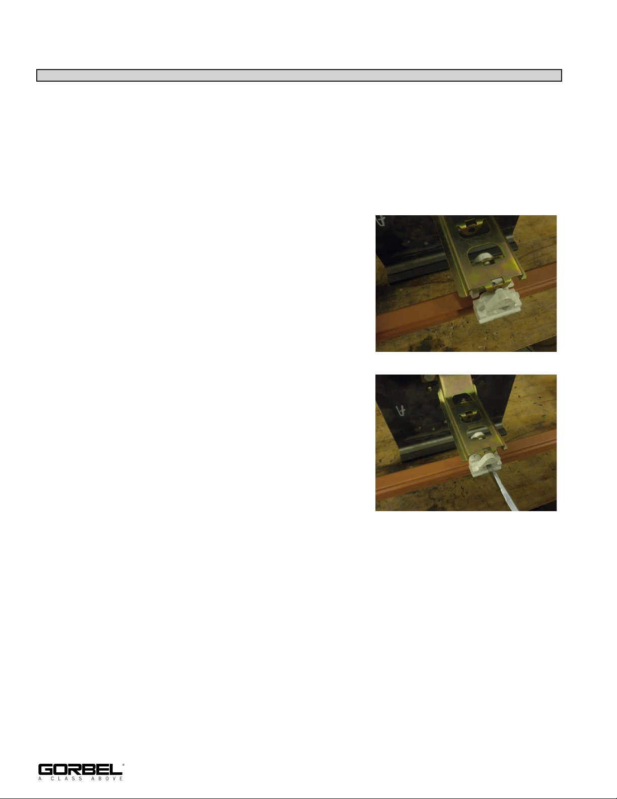
13.5 Once the mounting brackets are secured,
simultaneously mount the insulators to the conductor
bar and mounting brackets. Loosen the screw in the
insulator and lay the insulator over the top of the bars.
Lift the bar and insulator to the level of the bracket
and slide the insulator along the bar until it lines up
with the bracket. Then fit the two nibs, on the upper
ears of the insulator, into the holes provided for them
in the bracket (diagrams 13E and 13F). Make sure
that the nibs are in the holes and the insulators are in
the holes and the insulators are pressed firmly into
the grooved parts of the SAFPOWRBAR® cover, and
then tighten screw. Never force nibs into bracket or
force the insulator over the conductor bar.
Diagram 13E.
Note: For illustrative purposes, only one conductor
and insulator is shown. The conductor(s) nearest the
beam web must be installed first to allow access to
the screws to tighten down the insulator(s).
13.6 Continue mounting all SAFPOWRBAR by repeating
Diagram 13F.
prior steps until the entire conductor bar system
(mounting brackets, insulator, and conductor bar) is mounted to the runways. The ends of
adjacent sections of conductor bar should be butted together. The joints should always be
at least 6” away from an insulator to allow room for coupling cover.
Coupling Conductor Bars
Note: The insulating cover will be shipped cut back 2-1/8” from each end of the conductor.
Each joint will therefore have a gap in the insulating cover of 4-1/4” allowing for the
coupling. When conductor bars are cut to length in the field, the covering must be cut
back 2-1/8” from the freshly cut end before coupling bars together.
22
9/18 Rev. F
Page 27
STEP 13 - RUNWAY CONDUCTOR BAR INSTALLATION (SAFPOWRBAR®) (CONT.)
(for Safe-Lec Runway Conductor Bar Installation, go back to Step 12, page 18)
Coupling Conductor Bars (Continued)
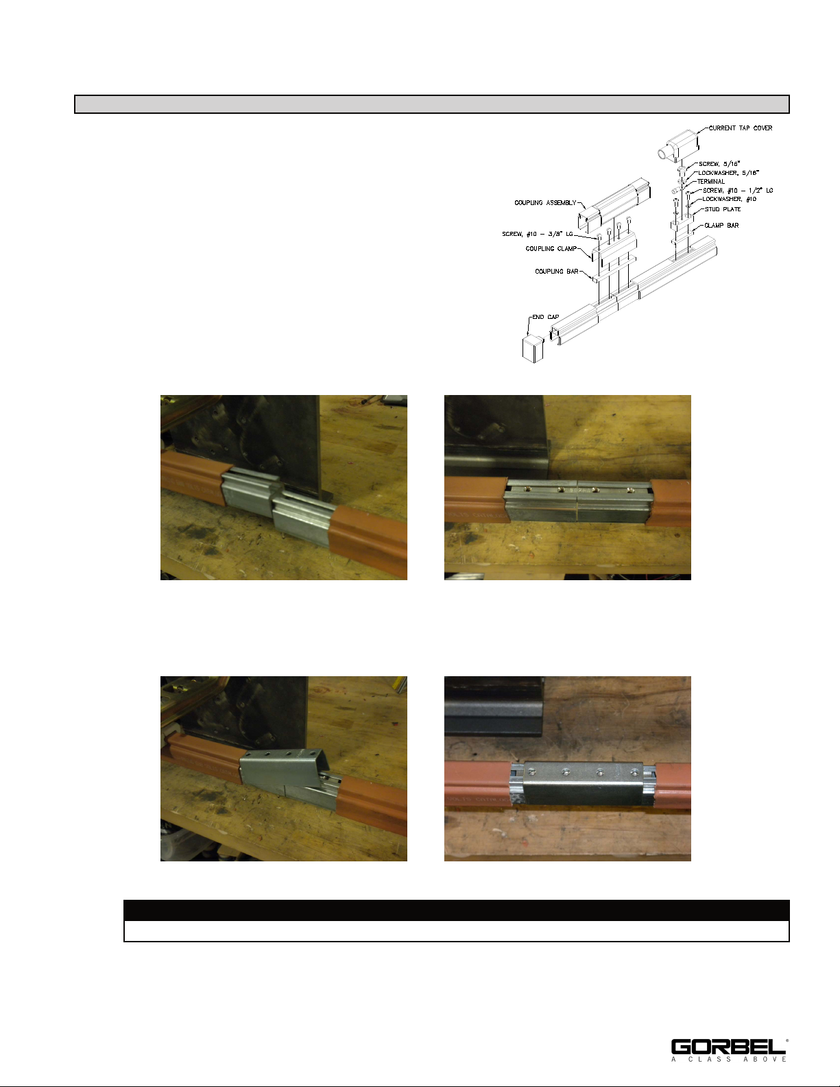
13.7 (See diagram 13G for complete assembly.) To
couple bars together, pull the two ends to be
joined apart and insert the coupling bar entirely
into the upper opening of one bar. Allow the
conductor bars to go back together and slide the
coupling bar half way into the adjoining bar so
that it is centered over the joint (diagrams 13H
and 13J).
Diagram 13G.
Diagram 13H. Diagram 13J.
13.8 Center the coupling clamp over the joint and tip to a 30-45 degree angle. Press one end
over the bar (diagrams 13K and 13L).
Diagram 13K. Diagram 13L.
WARNING
Do not spread clamp before installing, as clamp should be pressed onto bar.
13.9 Snap the coupling clamp down into place.
9/18 Rev. F
23
Page 28
STEP 13 - RUNWAY CONDUCTOR BAR INSTALLATION (SAFPOWRBAR®) (CONT.)
(for Safe-Lec Runway Conductor Bar Installation, go back to Step 12, page 18)
Coupling Conductor Bars (Continued)
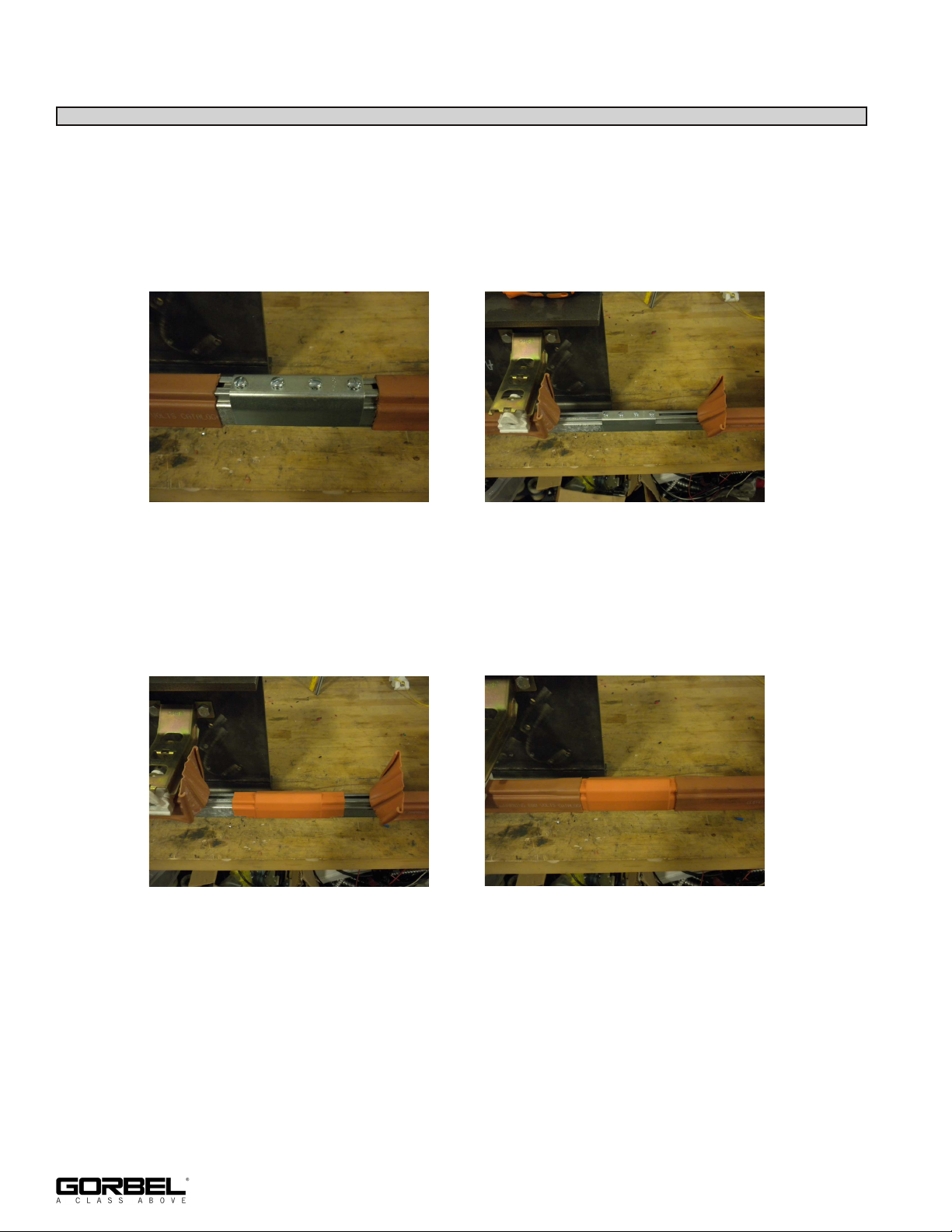
13.10 Insert the provided screws through holes in the coupling clamp and into tapped holes in
coupling bar and fully tighten (diagram 13M).
13.11 Pull back insulating cover on conductor bar 2-3 inches from the ends of the coupling
clamp (diagram 13N).
Diagram 13M.
Diagram 13N.
13.12 Place coupling cover over coupling clamp making sure the lips of the cover are firmly
hooked over conductor bar legs (diagram 13P).
13.13 Replace insulating covers on conductor bars that were pulled back in Step 13.11 covering
the ends of the coupling cover (diagram 13Q).
Diagram 13P.
Diagram 13Q.
Note: Splices may be located anywhere within the 66” between adjacent conductor
mounting brackets. SAFPOWRBAR® splices may not be placed outside the last mounting
bracket and thus cantilevering an entire section of bar.
24
9/18 Rev. F
Page 29
STEP 13 - RUNWAY CONDUCTOR BAR INSTALLATION (SAFPOWRBAR®) (CONT.)
(for Safe-Lec Runway Conductor Bar Installation, go back to Step 12, page 18)
Mounting Current Tap
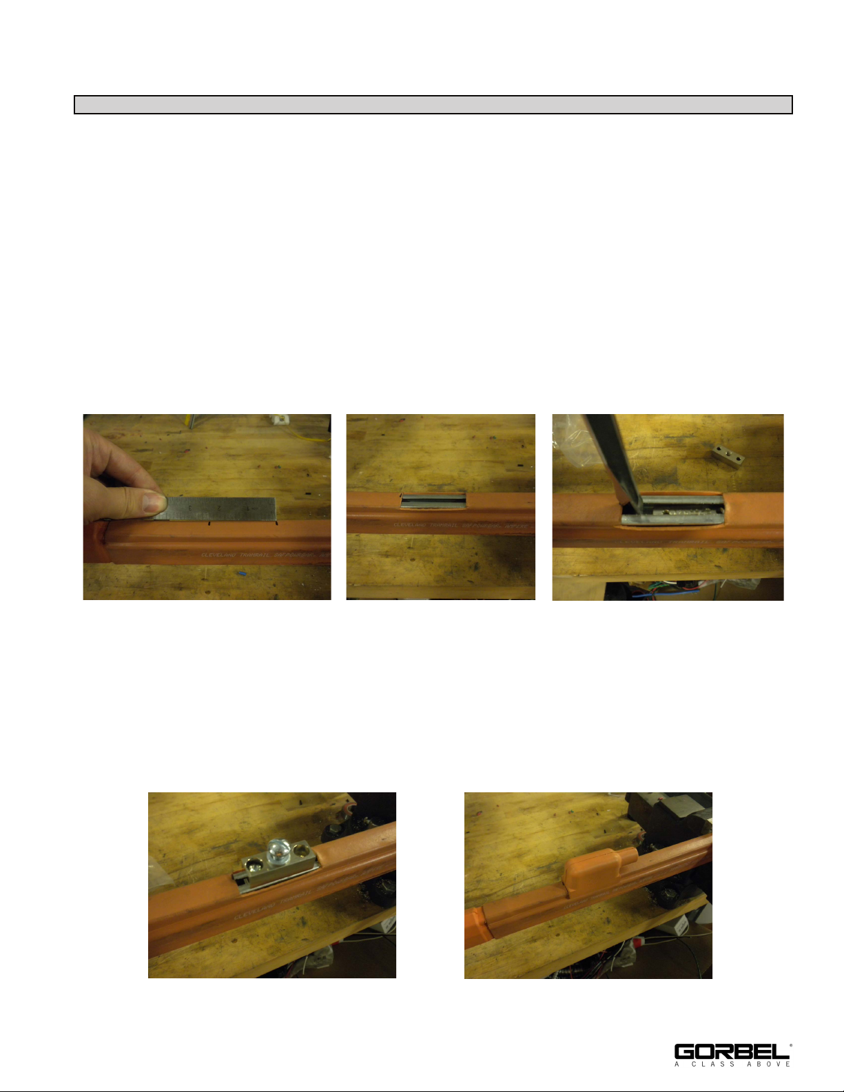
13.14 One current tap is required for each continuous run of conductor bar. Determine the tap
location and mark for a 2-1/4” cut on the conductor cover (diagram 13R).
13.15 Cut the cover at the tap location flush or slightly below the top of the conductor bar
(diagram 13S).
13.16 Place the clamp plate in the upper slot of the conductor bar at a slight angle and spread
the upper lips of the conductor bar slightly by wedging them apart with a flat-bladed
screwdriver (or similar), allowing the clamp plate to slide into the upper slot (diagram
13T).
Note: If the tap is located close to a support, the insulator mounting hardware may have
to be loosened in order to spread the upper lips of the conductor bar.
Diagram 13R. Diagram 13S.
Diagram 13T.
13.17 Fasten the stud plate to the clamp plate with screws and lockwashers (diagram 13U).
13.18 Thread wire through terminal cover and crimp terminal to wire. The hole in the terminal
must be at least 11/32” in diameter (wire and terminal not shown for clarity).
13.19 Attach terminal to stud plate and slide terminal cover over current tap forcing the arrow on
cover into upper slot of conductor bar (diagram 13V).
Diagram 13U.
Diagram 13V.
9/18 Rev. F
25
Page 30
STEP 13 - RUNWAY CONDUCTOR BAR INSTALLATION (SAFPOWRBAR®) (CONT.)
(for Safe-Lec Runway Conductor Bar Installation, go back to Step 12, page 18)
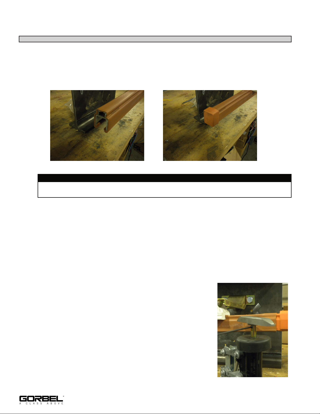
Mounting End Cap
13.20 Ensure that the end of the cover is flush with the conductor bar. Press the end cap’s
rectangular boss in to the top channel of the conductor bar until the cap is seated against
the end of the bar. The cover will need to be tucked into the end cap as it is slid on. A
small rubber mallet may make the installation easier (diagrams 13W and 13X).
Diagram 13W.
Diagram 13X.
WARNING
Standard conductor bar lengths ship with 2-1/8” of exposed bar at each end. Any exposed
bar at the end of a run must be cut off flush with the cover before installing end cap.
Installation of ST Collectors
13.21 ST collectors mount to drive idler heads with a steel rod that is bolted to the collector and
slips into a bracket on the heads.
Note: Collectors must be installed “inboard” of the drive or idler heads so they ride on the
conductor bar between the heads. For 2+2 conductor bar systems, one collector is
mounted near each wheel. For 3+1 systems, two collectors mount near one of the wheels.
The inner collector must ride in the inner conductor and the outer collector must ride in
the outer conductor. The collector opposite this pair must ride in the middle conductor,
with the single collector riding in the single conductor. Verify that the collectors do not
interfere with each other. For other configurations, contact
Customer Service for collector orientations.
13.22 Place shoe on split collector stem with “DOWN” marking in
the down position on the stem. Ensure that the shoe is fully
seated on the shoulder of the shaft and tighten the set screw
to hold the shoe firmly in place (diagram 13Y).
26
Diagram 13Y.
9/18 Rev. F
Page 31
STEP 13 - RUNWAY CONDUCTOR BAR INSTALLATION (SAFPOWRBAR®) (CONT.)
(for Safe-Lec Runway Conductor Bar Installation, go back to Step 12, page 18)
Installation of ST Collectors (Continued)
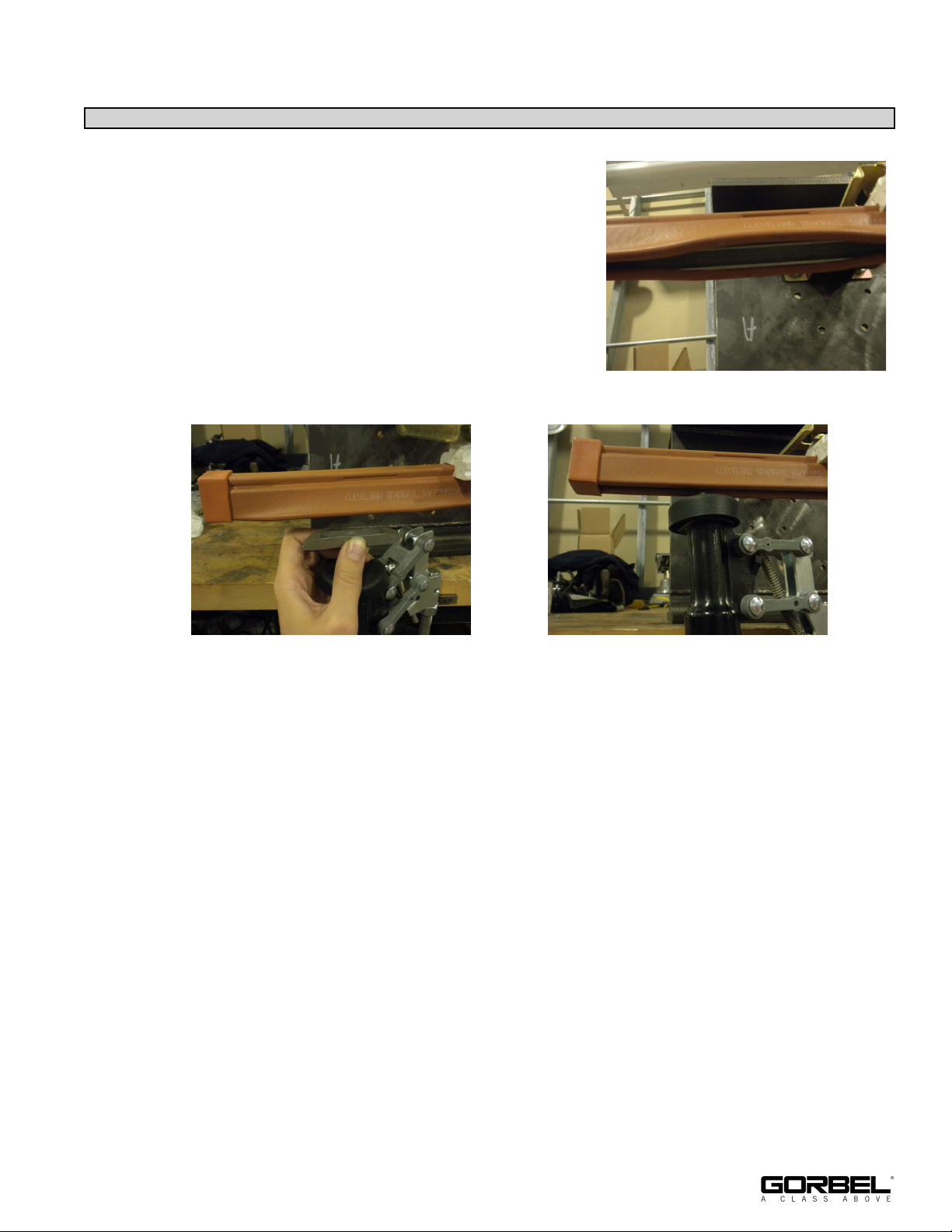
13.23 Unseat the lower edges of the conductor cover to
allow the shoe to slip through (diagram 13Z). Twist
shoe 150° so its long axis is parallel to the conductor
bar. Press down on the collector, compressing it so
the shoe is below the lower surface of the conductor
bar (diagram 13AA). Rotate the collector so it is
under the conductor bar and slowly release the
collector so the shoe gently rests in the conductor
bar. Check to ensure there is no binding and that the
shoe is making firm contact with the conductor bar.
Reseat the edges of the cover (diagram 13AB).
Diagram 13Z.
Diagram 13AA.
Diagram 13AB.
9/18 Rev. F
27
Page 32
STEP 14 - SWAY BRACE (OPTIONAL) INSTALLATION
NOTE: SWAY BRACING BY OTHERS
Support assemblies are designed to AISC (American Institute of Steel Construction)
specifications. If reduced movement of support assemblies is desired, then sway bracing (not
included) can be added. The installer or end user must determine the possible locations of the
bracing based on the specific application.
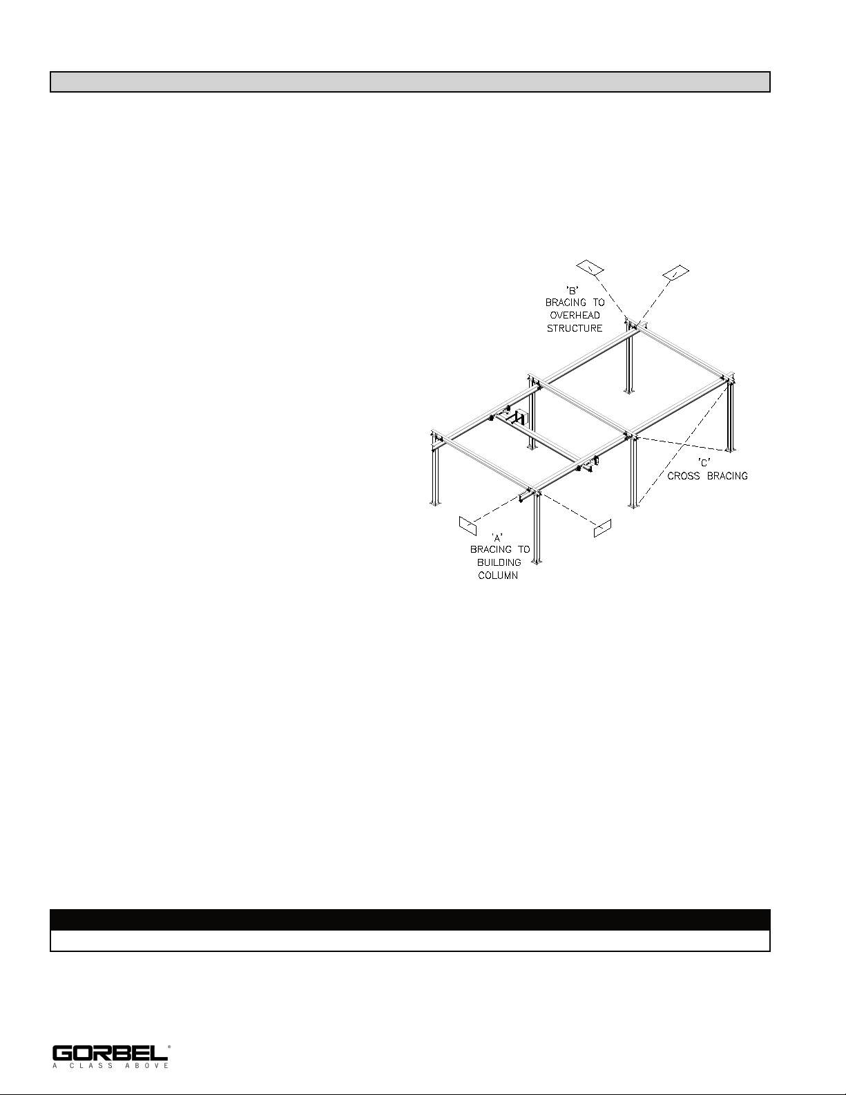
Bracing can be added in one of three formats, or a combination of any three.
A) The most typical place to brace is directly
to a building column. Providing a brace
from a building column to the lateral (side)
and longitudinal (lengthwise) axis of the
support steel provided extreme rigidity
throughout the system, and requires only
minimal locations (2 or 3 corners of the
system is typically adequate, see ‘A’ in
diagram 14A.
B) Another method is to brace back to the
ceiling above the crane. Again, bracing at
the corners of the system in both a lateral
and longitudinal direction is sufficient (see
‘B’ in diagram 14A), providing the
distance to the ceiling is not greater than
10 feet. For distances greater than 10 feet,
additional points may need to be braced
both laterally and longitudinally at the
discretion of the end user and/or the installer.
Diagram 14A. Examples of typical sway bracing locations.
C) Finally, if the system is located at a point where it is not practical or possible to brace to the
building columns or the ceiling structure, cross bracing can be done. This can be added at
the sides of the system (see ‘C’ in diagram 14A) to control longitudinal sway, or across the
open ends to limit lateral motion (not shown). This can also be added to the top of the
system, but should be check to make sure that it does not interfere with the travel of the
bridge.
It should be noted that the use of sway bracing is purely subjective because it is not a requirement of Gorbel, Inc. No specifications exist detailing appropriate methods, and the ultimate
quantity and type is at the discretion of the user and installer. If bracing, always determine if
the building structure is adequate.
WARNING
If bracing, brace to the headers not the columns.
28
9/18 Rev. F
Page 33

STEP 15 - FINAL STEPS
TIP: Do not throw away this manual: the maintenance schedule is on the back cover. Keep
Packing List, Installation Manual, General Arrangement Drawing, and any other inserts
filed together in a safe place.
15.1 If sway bracing is desired (not required), be sure that crane is properly braced. Refer to
Step 14, Sway Brace Installation.
15.2 Verify that all bolts are tightened to specifications and lockwashers are compressed.
15.3 Be sure all endstops are installed and functional.
15.4 Verify that the power supply is in conformance with crane specifications as ordered.
15.5 Load test is required (by others). It should be performed per latest ANSI B30.11
specification.
15.6 If necessary, touch up crane with paint provided.
9/18 Rev. F
29
Page 34

CRANE OPERATOR INSTRUCTIONS
Overhead Patented Track cranes and jib cranes generally handle materials over working areas where there are personnel. Therefore, it is important for the Crane
Operator to be instructed in the use of the crane and to understand the severe consequences of careless operation.
It is not intended that these suggestions take precedence over existing plant safety rules and regulations or OSHA regulations. However, a thorough study of the
following information should provide a better understanding of safe operation and afford a greater margin of safety for people and machinery on the plant floor.
It must be recognized that these are suggestions for the Crane Operator’s use. It is the responsibility of the owner to make personnel aware of all federal, state and
local rules and codes, and to make certain operators are properly trained.
Qualifications
Crane operation, to be safe and efficient, requires skill: the exercise of extreme care and good judgement, alertness and concentration, and rigid adherence to proven
safety rules and practices as outlined in applicable and current ANSI and OSHA safety standards. In general practice, no person should be permitted to operate a
crane:
• Who cannot speak the appropriate language or read and understand the printed instructions.
• Who is not of legal age to operate this type of equipment.
• Whose hearing or eyesight is impaired (unless suitably corrected with good depth perception).
• Who may be suffering from heart or other ailments which might interfere with the operator’s safe performance.
• Unless the operator has carefully read and studied this operation manual.
• Unless the operator has been properly instructed.
• Unless the operator has demonstrated his instructions through practical operation.
• Unless the operator is familiar with hitching equipment and safe hitching equipment practices.
Handling the Bridge Travel Motion
Before using the bridge of the crane, the operator should be sure the hook is high enough to clear any obstruction. Before a load is handled by the crane, the bridge
should be brought into position so that it is directly over the load. Start the load slowly and bring it up to speed gradually. Approaching the place where it is desired to
stop the bridge, reduce the bridge speed.
Handling the Trolley Motion
Before a load is handled, the hoist should be positioned directly over the load that is to be handled. When the slack is taken out of the slings, if the hoist is not directly
over the load, bring it directly over the load before hoisting is continued. Failure to center the hoist over the load may cause the load to swing upon lifting. Always start
the trolley motion slowly and reduce the trolley speed gradually.
Handling the Hoist Motion
Refer to the lifting (hoist) equipment’s operating instructions.
GENERAL SUGGESTIONS
Know Your Crane
Crane operators should be familiar with the principal parts of a crane and have a thorough knowledge of crane control functions and movements. The crane operator
should be required to know the location and proper operation of the main conductor disconnecting means for all power to the attachments on the crane.
Responsibility
Each crane operator should be held directly responsible for the safe operation of the crane. Whenever there is any doubt as to SAFETY, the crane operator should
stop the crane and refuse to handle loads until: (1) safety has been assured or (2) the operator has been ordered to proceed by the supervisor, who then assumes all
responsibility for the SAFETY of the lift.
Do not permit ANYONE to ride on the hook or a load.
Inspection
Test the crane movement and any attachments on the crane at the beginning of each shift. Whenever the operator finds anything wrong or apparently wrong, the
problem should be reported immediately to the proper supervisor and appropriate corrective action taken.
Operating Suggestions
One measure of a good crane operator is the smoothness of the crane operation. The good crane operator should know and follow these proven suggestions for safe,
efficient crane handling.
1. The crane should be moved smoothly and gradually to avoid abrupt, jerky movements of the load. lack must be removed from the sling and hoisting ropes
before the load is lifted.
2. Center the crane over the load before starting the hoist to avoid swinging the load as the lift is started. Loads should not be swung by the crane to reach areas
not under the crane.
3. Crane-hoisting ropes should be kept vertical. Cranes shall not be used for side pulls.
4. Be sure everyone in the immediate area is clear of the load and aware that a load is being moved.
5. Do not make lifts beyond the rated load capacity of the crane, sling chains, rope slings, etc.
6. Make certain that before moving the load, load slings, load chains, or other lifting devices are fully seated in the saddle of the hook with hook latch closed (if
equipped with hook latch).
7. Check the be sure that the load and/or bottom block is lifted high enough to clear all obstructions when moving boom or trolley.
8. At no time should a load be left suspended from the crane unless the operator has the push button with the power on, and under this condition keep the load as
close as possible to the floor to minimize the possibility of an injury if the load should drop. When the crane is holding a load, the crane operator should remain
at the push button.
9. Do not lift loads with sling hooks hanging loose. If all sling hooks are not needed, they should be properly stored, or use a different sling.
10. All slings or cables should be removed from the crane hooks when not in use (dangling cables or hooks hung in sling rings can inadvertently snag other objects
when the crane is moving).
11. Operators shall not carry loads and/or empty bottom blocks over personnel. Particular additional caution should be practiced when using magnet or vacuum
devices. Loads, or parts of loads, held magnetically could drop. Failure of power to magnets or vacuum devices can result in dropping the load. Extra precaution
should be exercised when handling molten metal in the proximity of personnel.
12. Whenever the operator leaves the crane the following procedure should be followed:
• Raise all hooks to an intermediate position.
• Spot the crane at an approved designated location.
• Place all controls in the “off” position.
• Open the main switch to the “off” position.
• Make visual check before leaving the crane.
13. In case of emergency or during inspection, repairing, cleaning or lubrication, a warning sign or signal should be displayed and the main switch should be locked
in the “off” position. This should be done whether the work is being done by the crane operator or by others.
14. Contact with rotation stops or trolley end stops shall be made with extreme caution. The operator should do so with particular care for the safety of persons
below the crane, and only after making certain that any persons on the other cranes are aware of what is being done.
15. ANY SAFETY FEATURES AND MECHANISMS BUILT IN OR OTHERWISE PROVIDED WITH THE CRANE BY CLEVELAND TRAMRAIL ARE REQUIRED
FOR THE SAFE OPERATION OF THE CRANE. DO NOT, UNDER ANY CIRCUMSTANCES, REMOVE OR OTHERWISE IMPAIR OR DISABLE THE PROPER
FUNCTIONING OF ANY CRANE SAFETY MECHANISMS OR FEATURES BUILT-IN OR OTHERWISE PROVIDED BY CLEVELAND TRAMRAIL FOR SAFE
OPERATION OF THE CRANE. ANY REMOVAL, IMPAIRMENT OR DISABLING OF ANY SUCH SAFETY MECHANISMS OR FEATURES OR OTHER USE OR
OPERATION OF THE CRANE WITHOUT THE COMPLETE AND PROPER FUNCTIONING OF ANY SUCH SAFETY MECHANISMS OR FEATURES
AUTOMATICALLY AND IMMEDIATELY VOIDS ANY AND ALL EXPRESS AND IMPLIED WARRANTIES OF ANY KIND OR NATURE.
30
9/18 Rev. F
Page 35

LIMITED WARRANTY
It is agreed that the equipment purchased hereunder is subject to the following LIMITED warranty and no other. Gorbel warrants the manual or motorized Patented
Track Crane products to be free from defects in material or workmanship for a period of two years or 4,000 hours use from date of shipment in class C service. This
warranty shall not cover failure or defective operation caused by operation in excess of recommended capacities, misuses, negligence or accident, and alteration or
repair not authorized by Gorbel. No system shall be field modified after manufacture without the written authorization of Gorbel, Inc. Any field modification made to the
system without the written authorization of Gorbel, Inc. shall void Gorbel’s warranty obligation. OTHER THAN AS SET FORTH HEREIN, NO OTHER EXPRESS
WARRANTIES, AND NO IMPLIED WARRANTIES, ORAL OR WRITTEN, INCLUDING BUT NOT LIMITED TO THE WARRANTIES OF MERCHANTABILITY OR
FITNESS FOR A PARTICULAR PURPOSE, ARE MADE BY GORBEL WITH RESPECT TO ITS PRODUCTS AND ALL SUCH WARRANTIES ARE HEREBY
SPECIFICALLY DISCLAIMED. GORBEL SHALL NOT BE LIABLE UNDER ANY CIRCUMSTANCES FOR ANY INCIDENTAL, SPECIAL AND/OR CONSEQUENTIAL
DAMAGES WHATSOEVER, WHETHER OR NOT FORESEEABLE, INCLUDING BUT NOT LIMITED TO DAMAGES FOR LOST PROFITS AND ALL SUCH
INCIDENTAL, SPECIAL AND/OR CONSEQUENTIAL DAMAGES ARE HEREBY ALSO SPECIFICALLY DISCLAIMED. Gorbel’s obligation and Purchaser’s or end
user’s sole remedy under this warranty is limited to the replacement or repair of Gorbel’s products at the factory, or at the discretion of Gorbel, at a location designated
by Gorbel. Purchaser or end user shall be solely responsible for all freight and transportation costs incurred in connection with any warranty work provided by Gorbel
hereunder. Gorbel will not be liable for any loss, injury or damage to persons or property, nor for damages of any kind resulting from failure or defective operation
of any materials or equipment furnished hereunder. Components and accessories not manufactured by Gorbel are not included in this warranty. Purchaser’s or end
user’s remedy for components and accessories not manufactured by Gorbel is limited to and determined by the terms and conditions of the warranty provided by the
respective manufacturers of such components and accessories.
A) DISCLAIMER OF IMPLIED WARRANTY OF MERCHANTABILITY
Gorbel and Purchaser agree that the implied warranty of merchantability is excluded from this transaction and shall not apply to the goods
involved in this transaction.
B) DISCLAIMER OF IMPLIED WARRANTY OF FITNESS FOR PARTICULAR PURPOSE
Gorbel and Purchaser agree that the implied warranty of fitness for particular purpose is excluded from this transaction and shall not apply to
the goods involved in this transaction.
C) DISCLAIMER OF EXPRESS WARRANTY
Gorbel’s agents, or dealer’s agents, or distributor’s agents may have made oral statements about the machinery and equipment described in
this transaction. Such statements do not constitute warranties, and Purchaser agrees not to rely on such statements. Purchaser also agrees
that such statements are not part of this transaction.
D) DISCLAIMER OF SPECIAL, INCIDENTAL AND CONSEQUENTIAL DAMAGES
Gorbel and Purchaser agree that any claim made by Purchaser which is inconsistent with Gorbel’s obligations and the warranty remedies
provided with Gorbel’s products, and in particular, special, incidental and consequential damages, are expressly excluded.
E) DEALER OR DISTRIBUTOR NOT AN AGENT
Gorbel and Purchaser agree that Purchaser has been put on notice that dealer or distributor is not Gorbel’s agent in any respect for any
reason. Gorbel and Purchaser also agree that Purchaser has been put on notice that dealer or distributor is not authorized to incur any
obligations or to make any representations or warranties on Gorbel’s behalf other than those specifically set forth in Gorbel’s warranty provided
in connection with its product.
F) MERGER
This warranty agreement constitutes a final and complete written expression of all the terms and conditions of this warranty and is a complete
and exclusive statement of those terms.
G) PAINTING
Every crane (excluding components) receives a quality paint job before leaving the factory. Unfortunately, no paint will protect against the
abuses received during the transportation process via common carrier. We have included at least one (1) twelve ounce spray can for touchup
with each crane ordered (unless special paint was specified). If additional paint is required, contact a Gorbel® Customer Service
Representative at 1-800-821-0086 or 1-585-924-6262.
Title and Ownership:
Title to the machinery and equipment described in the foregoing proposal shall remain with Gorbel and shall not pass to the Purchaser until the full amount
herein agreed to be paid has been fully paid in cash.
Claims and Damages:
Unless expressly stated in writing, goods and equipment shall be at Purchaser’s risk on and after Seller’s delivery in good shipping order to the Carrier. Gorbel
shall in no event be held responsible for materials furnished or work performed by any person other than it or its authorized representative or agent.
Cancellations:
If it becomes necessary for the purchaser to cancel this order wholly or in part, he shall at once so advise Gorbel in writing. Upon receipt of such written notice
all work will stop immediately. If the order entails only stock items, a flat restocking charge of 15% of the purchase price will become due and payable by
Purchaser to Gorbel. Items purchased specifically for the canceled order shall be charged for in accordance with the cancellation charges of our supplier plus
15% for handling in our factory. The cost of material and/or labor expended in general fabrication for the order shall be charged for on the basis of total costs to
Gorbel up to the time of cancellation plus 15%.
Returns:
No equipment, materials or parts may be returned to Gorbel without express permission in writing to do so.
Extra Charge Delay: If Purchaser delays or interrupts progress of Seller’s performance, or causes changes to be made, Purchaser agrees to reimburse Gorbel
for expense, if any, incident to such delay.
Changes and Alterations:
Gorbel reserves the right to make changes in the details of construction of the equipment, as in its judgment, will be in the interest of the Purchaser; will make
any changes in or additions to the equipment which may be agreed upon in writing by the Purchaser; and Gorbel is not obligated to make such changes in
products previously sold any customer.
Third Party Action:
Should Gorbel have to resort to third party action to collect any amount due after thirty (30) days from date of invoice, the Purchaser agrees to pay collection
costs, reasonable attorney’s fees, court costs and legal interest.
OSHA Responsibilities:
Gorbel agrees to fully cooperate with Purchaser in the design, manufacture or procurement of safety features or devices that comply with OSHA regulations. In
the event additional equipment or labor shall be furnished by Gorbel, it will be at prices and standard rates then in effect, or as may be mutually agreed upon at
the time of the additional installation.
Equal Employment Opportunity:
Gorbel agrees to take affirmative action to ensure equal employment opportunity for all job applicants and employees without regard to race, color, age, religion,
sex, national origin, handicap, veteran, or marital status. Gorbel agrees to maintain non-segregated work facilities and comply with rules and regulations of the
Secretary of Labor or as otherwise provided by law or Executive Order.
9/18 Rev. F
31
Page 36

This page intentionally left blank.
32
9/18 Rev. F
Page 37

PERIODIC INSPECTION AND LUBRICATION RECOMMENDATIONS
The following is a checklist to be followed in performing periodic inspections and preventative
maintenance on Gorbel® Tarca® Systems. It is intended that this checklist be supplemented with
any additional instruction sheets and maintenance manuals sent with each job.
The frequency of inspection and lubrication recommendations presented herein is based upon
normal operating conditions of one complete handling cycle every 10 minutes throughout a
40-hour week. If the actual duty cycle of a particular unit is greater or less than this, the inspections and lubrications should be performed more frequently or less frequently in proportion.
Each industry has conditions peculiar to it, which may cause wear of certain parts. The tabulation
given is only general and may be supplemented by an individual maintenance department
program to meet its own particular requirements. Particular attention should be given to corrosive
conditions, excessive vibrations, extreme ambient temperature variations, and rough handling
conditions.
Questions regarding damaged, worn or cracked equipment components should be directed to
the Gorbel® Inside Sales Department at 800-821-0086 or 585-924-6262.
The recommendations contained herein are to be supplemented by any vendor instructions,
which are included in this manual.
WARNING: Power should be off and locked when performing maintenance on any part of the
system.
* State and local codes may require inspection and maintenance checks more often. Please
check the state and local code manuals in your area.
TRACKS, RUNWAYS & SUPPORT STEEL
ITEM COMPONENT MAINTENANCE FREQUENCY
Header-Column
1
Hardware
Header-Runway
2
Hardware
3 Column Anchoring Check for loose bolts & cracked fittings.
Sway Brace
4
Connection (if used)
5 Track
6 Joints
7 End Stops Check for loose bolts and for incipient cracks.
8 Paint Clean periodically and repaint where corrosion is present.
Check for loose bolts & cracked fittings. Check for full
compression of lock washer. Bolt should be tightened to
manufacturer’s specifications.
Check for loose bolts & cracked fittings. Check for full
compression of lock washer. Bolt should be tightened to
manufacturer’s specifications.
Check for loose bolts & cracked fittings.
Check for rail wear (replace if raised portion of tread is gone).
Check welds for incipient cracks. Check underside of rail for
wear from drive rollers if using tractor drives. When groove is
1/8” deep, replace track. Check side of rail for wear. When width
has decreased more than 1/8”, replace track.
Check for loose or worn hardware or if welded type, for incipient
cracks. Check for track alignment and that wheel rolling surface
is flush.
Every 1,000 hours
or 6 months
Every 1,000 hours
or 6 months
Every 1,000 hours
or 6 months
Every 1,000 hours
or 6 months
Every 2,000 hours
or yearly
Every 2,000 hours
or yearly
Every 2,000 hours
or yearly
Every 2,000 hours
or yearly
9/18 Rev. F
33
Page 38

BRIDGE
ITEM COMPONENT MAINTENANCE FREQUENCY
1 Controls
Push Buttons &
2
Pendant
Electric Brakes
3
(Disc)
4 Paint Clean periodically and repaint where corrosion is present.
Check for burned contacts, broken shading coils, worn or
cracked arc barriers, auxiliary contacts, and proper seating.
Check contacts. Tighten leads. Check for sticking buttons. Check
ground wire continuity. Check pendant cable top and
bottom for broken wires. Check strain chain to see that any pulling force is not put on pendant cables.
Adjust air gap for wear. Check lining thickness. Check for broken
shading coils. Check rotating disc at spline for excessive wear.
Every 1,000 hours
or 6 months
Every 1,000 hours
or 6 months
Every 750 hours or
4 months
Every 2,000 hours
or yearly
END TRUCK, TROLLEY & CARRIERS
ITEM COMPONENT MAINTENANCE FREQUENCY
Structural Frame &
1
Load Bars
Eye Bolts,
Suspension Pins &
2
Ball Joint Rocker
Assembly
Wheels & Guide
3
Rollers
4 Geared Drive
5 Belt Drive Check for belt wear
6 Motors
7 Control
Electric Brakes
8
(Disc)
9 Head Check for thrust washer wear and integrity.
Check for incipient cracks in welds and castings. Check for loose
bolts.
Check for loose or missing set screws or lock pins. Grease
spherical bearing housing monthly through grease fitting or
repack with clean grease at three (3) month intervals. Use
Calcium Sulfonate type grease (Peerless OG2 Red or equal).
Check for cracks and excessive wear. Note: When lubricating
through grease fitting or repacking, suspension pins and ball
joint rocker assembly should be raised approximately 1/4”.
Check for loose wheel bearings. Check wheels for proper
contact and tracking on rail. Check wheel diameter for wear
(replace when 1/4” under original diameter). Check axle nuts
for tightness. Lubricate using Calcium Sulfonate type grease
(Peerless OG2 Red or equal).
Check oil level. Change oil as ambient temperature requires (see
Lube List). Check gear wear through backlash. Check for worn
bearings (excessive noise). Check for loose bolts in gear case
cover.
Check motor after active use for excessive heat (130° C or 226°
F max. with class “B” insulation). Check motor bearings and oil
seals. Tighten loose bolts. Blow out dust. Lubricate. Also see
motor manufacturer’s recommendations.
Check for burned contacts. Check mechanical latch devices for
wear and freedom of movement. Check for loose connections.
Adjust air gap for wear. Check lining thickness. Check for broken
shading coils. Check rotating disc at spline for excessive wear.
See manufacturer’s recommendations.
Every 2,000 hours
or yearly
Every 150 hours or
1 month
Every 500 hours or
3 months
Every 750 hours or
4 months
Every 750 hours or
4 months
Every 1,000 hours
or 6 months
Every 1,000 hours
or 6 months
Every 750 hours or
4 months
Every 1,000 hours
or 6 months
34
9/18 Rev. F
Page 39

SAFE-LEC CONDUCTOR BAR
ITEM COMPONENT MAINTENANCE FREQUENCY
Contact shoes should be checked for wear. Check alignment of
collector to conductor bar. Base of collector should be directly
1 Collectors
2 Bar Covering Check to ensure no damage is visible.
3 Complete System
inline with associated conductor. Check collector pivot pins are
free from any contamination. Uneven shoe wear indicates less
than optimal collector alignment.
In environments that are subject to considerable build up of dust,
especially conductive dust, remove this dust by brushing.
Every 150 hours
or 1 month
Every 2,000 hours
or yearly
Every 2,000 hours
or yearly
SAFPOWRBAR® CONDUCTOR BAR
ITEM COMPONENT MAINTENANCE FREQUENCY
1 Bar
2 Couplings
3 Supports Check for loose bolts and/or screws and bent brackets.
4 Insulators
5 Bar Covering Check for accidental abrasion and peeled covering.
6 Current Taps
7 Grounds
8 Collectors
Check for corrosion, bowing, or sagging. Check alignment at
moving gaps. Realign if necessary.
Check bolt or screw tightness. Check for corroded contact
surfaces.
Check for loose bolts, sheared support ears, current carrying
deposits on surface.
Check bolt and terminal screw tightness. Check for corroded
contact surface.
Check for ground continuity. Check at load side of disconnect
switch (current off), with meg-ohm tester, for overall system insulation resistance.
Check for worn shoes. Check flexible leads from wheel clevis
pigtail or slide shoe shaft. Check tightness of lead connections.
Check for cracked insulators. On type “ST” collectors, check for
free movement or pantograph. Lubricate pivot pins as required.
Collector bracket tubes should be vertical within 1/16”. Replace if
necessary.
Every 2,000 hours
or yearly
Every 2,000 hours
or yearly
Every 2,000 hours
or yearly
Every 2,000 hours
or yearly
Every 2,000 hours
or yearly
Every 2,000 hours
or yearly
Every 2,000 hours
or yearly
Every 750 hours
or 4 months
HOIST (Refer to Hoist Manufacturer)
C-TRACK
ITEM COMPONENT MAINTENANCE FREQUENCY
1 Trolleys
2 Rollers Check all rollers for wear.
3 Hardware
4 C-Track Check channel for wear. Clear the running surface of any debris.
5 Cables Inspect cables for any cuts or cracks.
9/18 Rev. F
All trolleys are lubricated and sealed for life, therefore no
regreasing is required.
Check tightness (see torque specifications). Check cable clamps
on all trolleys, making sure cables remain secure.
35
Every 2,000 hours
or yearly
Every 2,000 hours
or yearly
Every 2,000 hours
or yearly
Every 2,000 hours
or yearly
Page 40
RECOMMENDED LUBRICANT LIST
WARNING
This produc
,
which are
more inf
Bushings and thrust washers without grease fitting, spray lube or general purpose oil.
Bushings and thrust washers with grease fittings:
Multi-purpose application and high temperature application:
Calcium Sulfonate type grease (Peerless OG2 Red or equal).
Ball or roller bearings through alemite fittings:
Multi-purpose application and high temperature application:
Calcium Sulfonate type grease (Peerless OG2 Red or equal).
Series “W” motor heads ............................................ Straight mineral oil - SAE-50
Type “MT” & “CH” tractors ......................................... Straight mineral oil - SAE-50
Compact drives (“L”) .......................................................... A.G.M.A. #8 compound
NOTE: When above equipment is used outdoors, we recommend a field change in oil (in some
cases as low as SAE-10), when cold weather arrives. Consult local lubrication engineer for recommended greases in acid fume atmosphere.
t can expose you to chemicals, including acrylonitrile
known to the State of California to cause cancer. For
ormation go to:
www.P65Warnings.ca.gov
linkedin.com/company/gorbel
600 Fishers Run, P.O. Box 593
Fishers, NY 14453-0593
Phone: (800) 821-0086
Fax: (800) 828-1808
E-Mail: [email protected]
http://www.gorbel.com
©2010 Gorbel, Inc.
All Rights Reserved
Facebook
Facebook.com/gorbelinc
youtube.com/gorbelmarkeng gorbel.com/blog
36
Twier
twier.com/gorbelinc
9/18 Rev. F
 Loading...