

Page 1
®
Installation, Operation,
& Maintenance Manual
IMPORTANT!
DO NOT DESTROY
Issued: 11/2018
Revised: 03/2019
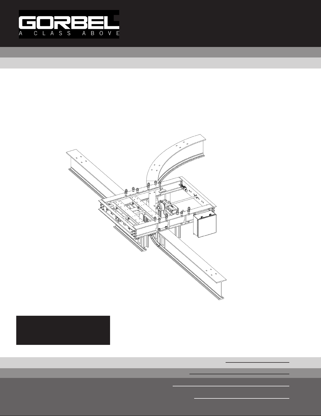
Tarca® Switch
Gorbel® Customer Order No. / Serial No.
Gorbel® Dealer
Date
Month
I Series
Year
Page 2

THIS PAGE INTENTIONALLY LEFT BLANK.
11/2018
Page 3

TABLE OF CONTENTS
Introduction ............................................................................................................................ 1
Models and Options .............................................................................................................. 2
Installation
Step 1 - Pre-assembly ................................................................................................................ 3
Step 2 - Attachment and Hole Layout ..........................................................................................4
Step 3 - Mounting .........................................................................................................................5
Step 4 - SAFPOWRBAR® Wiring (Option) ..................................................................................6
Step 5 - Control Wiring (Option) ..................................................................................................7
Step 6 - Motorized Operator (Option) ...................................................................................... 8-9
Limit Switch Adjustment ............................................................................................. 8-9
Step 7 - Pneumatic Operator (Option) .......................................................................................10
Step 8 - Manual Operator (Option) ............................................................................................10
Appendix A - Beam End Prep Diagrams .................................................................. 11-14
Appendix B - Wiring Diagrams.................................................................................. 15-18
Crane Operator / Start Up Instructions ............................................................................... 19
General Safety Requirements ............................................................................................. 19
Limited Warranty ................................................................................................................. 20
Inspection and Maintenance Schedule .......................................................................... 21-24
Questions? Concerns? Comments? Please call (800) 821-0086
11/2018
Page 4

THIS PAGE INTENTIONALLY LEFT BLANK.
11/2018
Page 5

INTRODUCTION
Thank you for choosing Gorbel® to solve your material handling needs. The innovative design and heavy-duty
construction of the Gorbel® product will provide a superior quality product that will offer years of long term value.
The hoist weight allowance is 15% of the crane’s capacity (for example, a crane rated for 6000 pounds, allows for a
6000-pound live load plus 900 pounds for the weight of the hoist). There is also an allowance of 15% of the crane
capacity for impact caused by hoist use. Gorbel® products will provide many years of dependable service by
following the installation and maintenance procedures described herein.
Gorbel® products are shipped in various stages of assembly and are installed under varying circumstances. As a
result, a complete guide with descriptions covering all variations is not possible. The following instructions are only to
be used as a general guide. Attention should be paid to the warnings and safety suggestions posted in this manual
and on the equipment.
Dimensions contained in this installation manual are for reference only and may differ for your particular
application.
Normal safety precautions: These include, but are not limited to:
• Checking for obstructions in travel
• Checking that all bolts and threaded rods are tight and have lock washers where applicable
• Making sure that end stops are in place and functional (i.e. stopping rolling equipment from exiting rail)
• Making sure that festooning cannot be snagged or pinched, whether it is electric or pneumatic
• For additional safety precautions, see page 19.
WARNING
Please read entire manual prior to starting installation.
WARNING
Gorbel Inc. assumes no responsibility for adequacy or integrity of the mounting surfaces or the structure that the
crane may be mounted to. Gorbel Inc. will not be liable for any loss, injury or damage to persons or property, nor
for damages of any kind, resulting from the failure or defective operation of any materials not supplied directly by
Gorbel Inc. Bracing systems, if used, must be approved by a local professional engineer.
WARNING
Before installing any crane system, it is critical you determine that your building will safely support the loads.
WARNING
Equipment described herein is not designed for, and should not be used for, lifting, supporting or transporting
humans. Failure to comply with any one of the limitations noted herein can result in serious bodily injury and/or
property damage. Check State and Local regulations for any additional requirements.
WARNING
Crane cannot be utilized as a ground: A separate ground conductor is required. For example, systems with 3 phase
power require three conductors plus one ground conductor.
WARNING
Reference the American Institute of Steel Construction (AISC) Manual of Steel Construction Specification
for Structural Joints using ASTM A325 or A490 Bolts, Installation, Pretensioned Joints, Calibrated Wrench
Pretensioning for the proper procedures to follow when using any torque tightening method.
11/2018
1
Page 6
MODELS AND OPTIONS
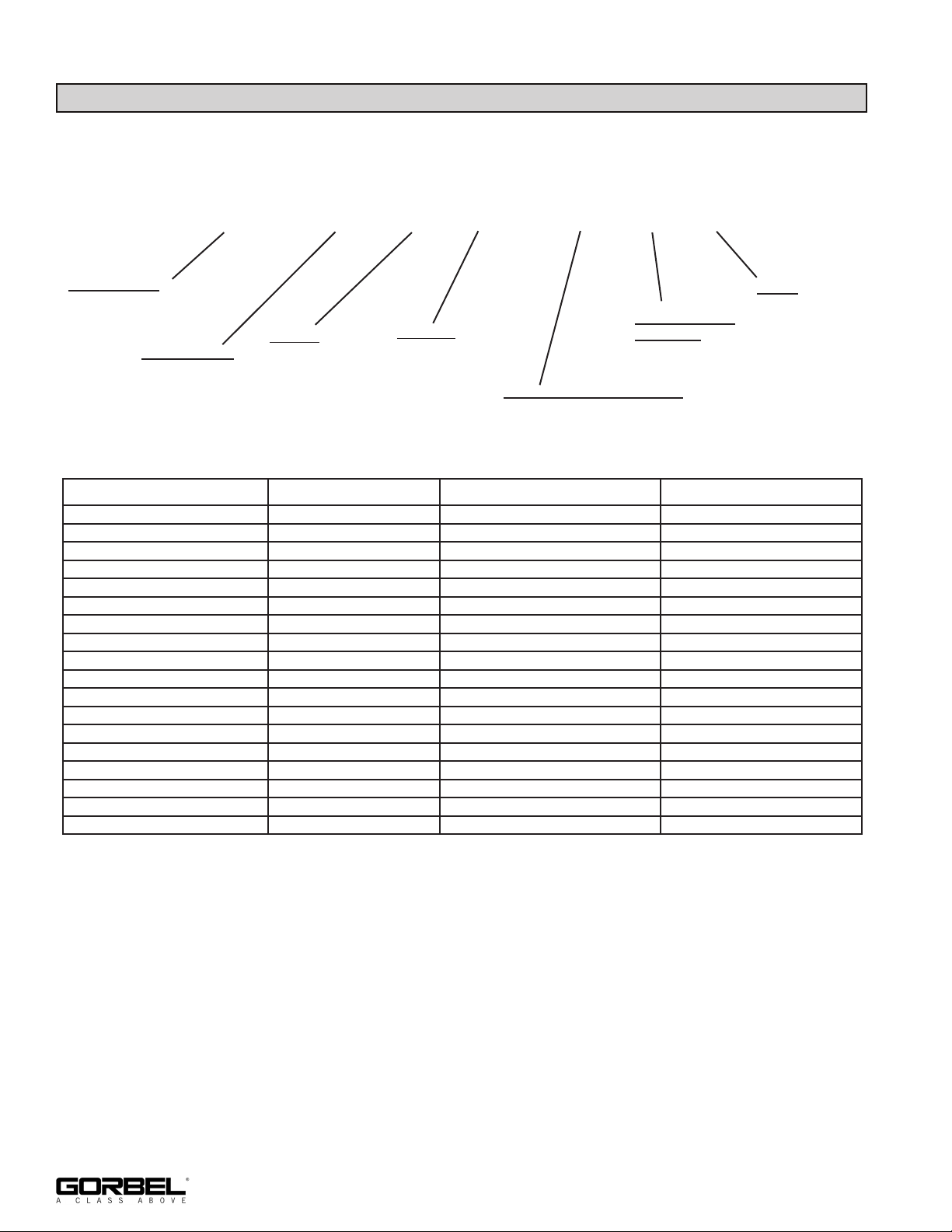
Part Number:
PT.SWITCH.KIT - I -
5000 - R - M - 460 - H - 4 - G
Track Series:
See Runway Section of
Sales Manual
Switch Style:
L = Left-Hand
R = Right-Hand
Y = Wye
T = 3-Way
Power:
H = Manual
M = Motorized
P = Pneumatic
Voltage:
208, 230, 460, 575
SAFPOWRBAR® Position:
N = None
H = High
L = Low
SAFPOWRBAR
Quantity:
0, 4
SWITCH STYLE POWER VOLTAGE SAFPOWRBAR®
Left/Right Hand Manual None None
Left/Right Hand Manual None High/Low
Left/Right Hand Motorized 208/230 or 460/575 None
Left/Right Hand Motorized 208/230 or 460/575 High/Low
Left/Right Hand Pneumatic 208/230 or 460/575 None
Left/Right Hand Pneumatic 208/230 or 460/575 High/Low
Wye Manual None None
Wye Manual None High/Low
Wye Motorized 208/230 or 460/575 None
Wye Motorized 208/230 or 460/575 High/Low
Wye Pneumatic 208/230 or 460/575 None
Wye Pneumatic 208/230 or 460/575 High/Low
3-Way Manual None None
3-Way Manual None High/Low
3-Way Motorized 208/230 or 460/575 None
3-Way Motorized 208/230 or 460/575 High/Low
3-Way Pneumatic 208/230 or 460/575 None
3-Way Pneumatic 208/230 or 460/575 High/Low
Paint:
G = Gray Green
B = Blue
Y = Yellow
O = Orange
S = Special
N = None
2
11/2018
Page 7

NOTE: It is recommended to install switch(es) first and align monorails to them.
STEP 1 - INSTALLATION
• It is recommended to install switch(es) first and align monorails to them.
• Read entire installation manual before you begin installing your switch.
• Study all instructions and drawings provided in this manual.
• Verify receipt of all materials in good condition. Check all hole punchings, beam dimensions
and suspension fittings prior to installation.
• Check packing list to make sure correct quantity of parts is included. Any missing items
should be noted and reported to a Gorbel® dealer.
• Tools and materials typically needed to assemble switch are as follows:
• Wrench/socket • Square
• Torque wrench • Tape measure
• Leveling tools • Ladders/man lifts
• Shims • Lifting device
• Standard switch throw is 11”. DO NOT ADJUST.
11/2018
3
Page 8
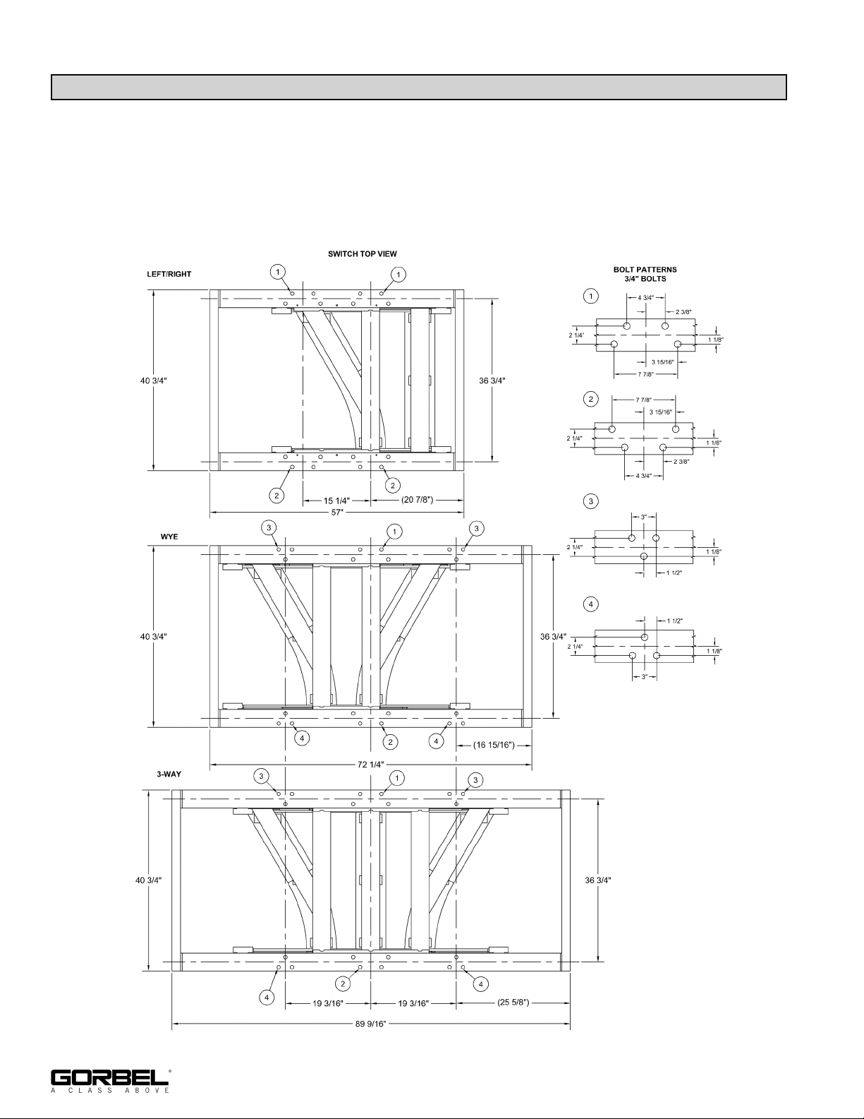
STEP 2 - ATTACHMENT AND HOLE LAYOUT
2.1 Attachment to support structure via 3/4” Grade A325 bolts. 3” long bolts are included.
Hardened washers and Anco lock-nuts are included and must be used. Maximum 1-3/8”
structural member thickness.
2.2 Layout and drill holes in support structures 13/16” nominal. 15/16” maximum hole diameter
per AISC.
Diagram 2A. Switch support detail.
4
11/2018
Page 9
STEP 3 - MOUNTING
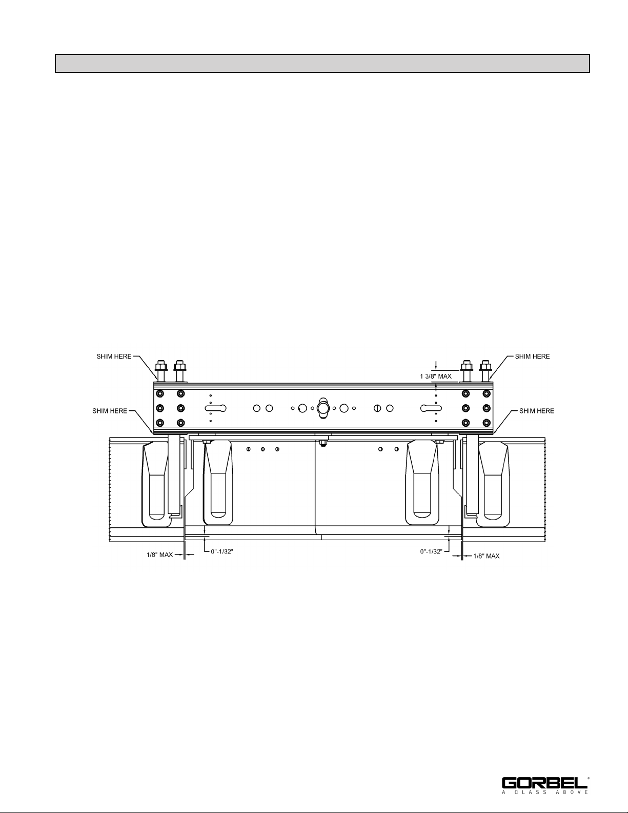
3.1 Shim frame to level the underside of the outer frame to prevent racking/twisting (shims
included).
3.2 Verify frame is square by checking diagonals.
3.3 Torque frame attachment hardware to 260 lb ft, Turn-of-Nut method is acceptable
3.4 If beams are not factory prepped, e
nd prep incoming beams. Additional parts required from
factory (see Appendix A on pages 11-14 for detail).
3.5 Use provided 3/4” A325 bolts, washers and nuts to loosely assemble monorail beam to
switch. Do not tighten yet.
3.6 Shim inlet and outlet beams 0” to 1/32” lower than switch track.
3.7 Set gap between inlets and switch track is 1/8” maximum. Ensure that beam ends do not
rub or bind as they pass each other.
3.8 Once beam is positioned, tighten beam attachment hardware. Torque to 260 lb ft. Turn-of
Nut method is acceptable.
Diagram 3A. Shim detail.
OUTLETINLET
11/2018
5
Page 10
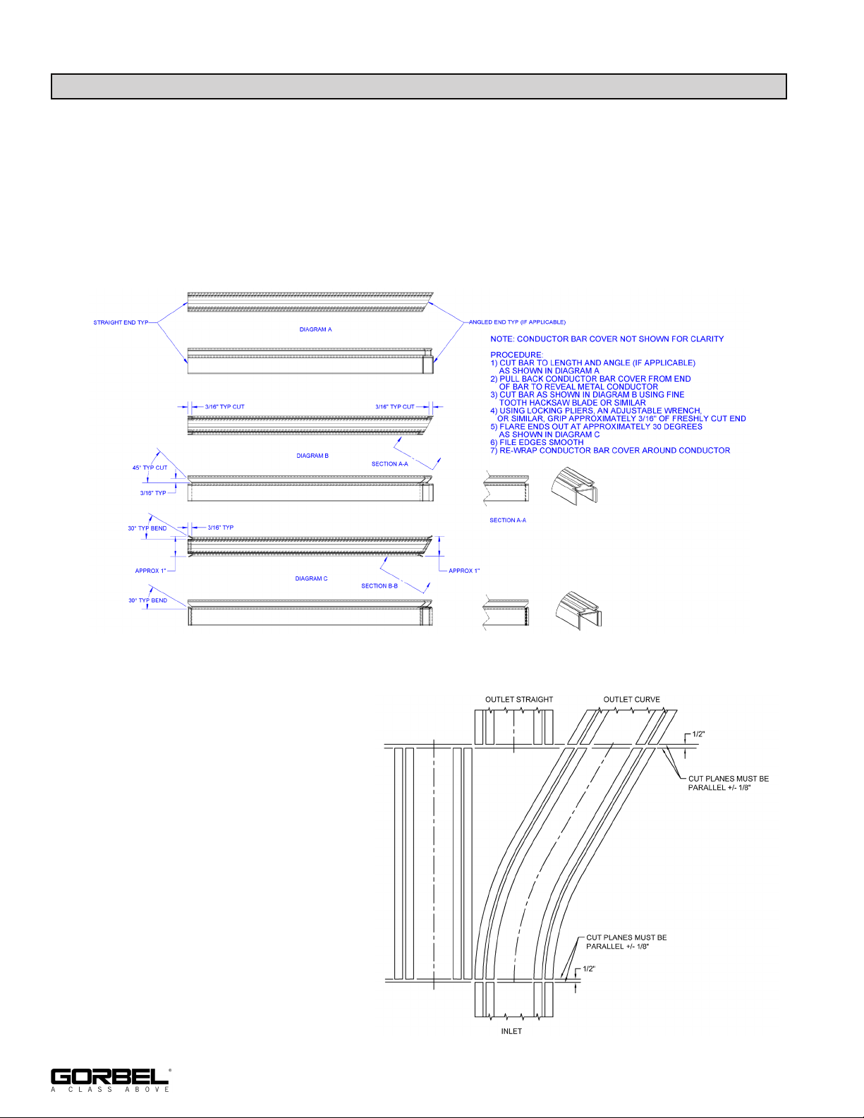
STEP 4 - SAFPOWRBAR® WIRING (OPTION)
4.1 Prior to installing SAFPOWRBAR on monorail beams, flare/prep bar ends. Refer to
diagram 4A for flaring procedure.
4.2 Gap between bar ends should be adjusted to 1/2”. It may be necessary to adjust the
position of the bars to ensure smooth traversing of the shoes. Refer to diagram 4B for
finished bar layout.
4.3 Actuate inner frame to verify bar clearance.
Diagram 4A. SAFPOWRBAR® Flaring
4.4 Switch jumper harness and current
taps are provided from factory.
Refer to Monorail Tarca® system
install manual, page 20, for
mounting current taps to
SAFPOWRBAR.
Procedure.
6
Diagram 4B. SAFPOWRBAR®
11/2018
Page 11
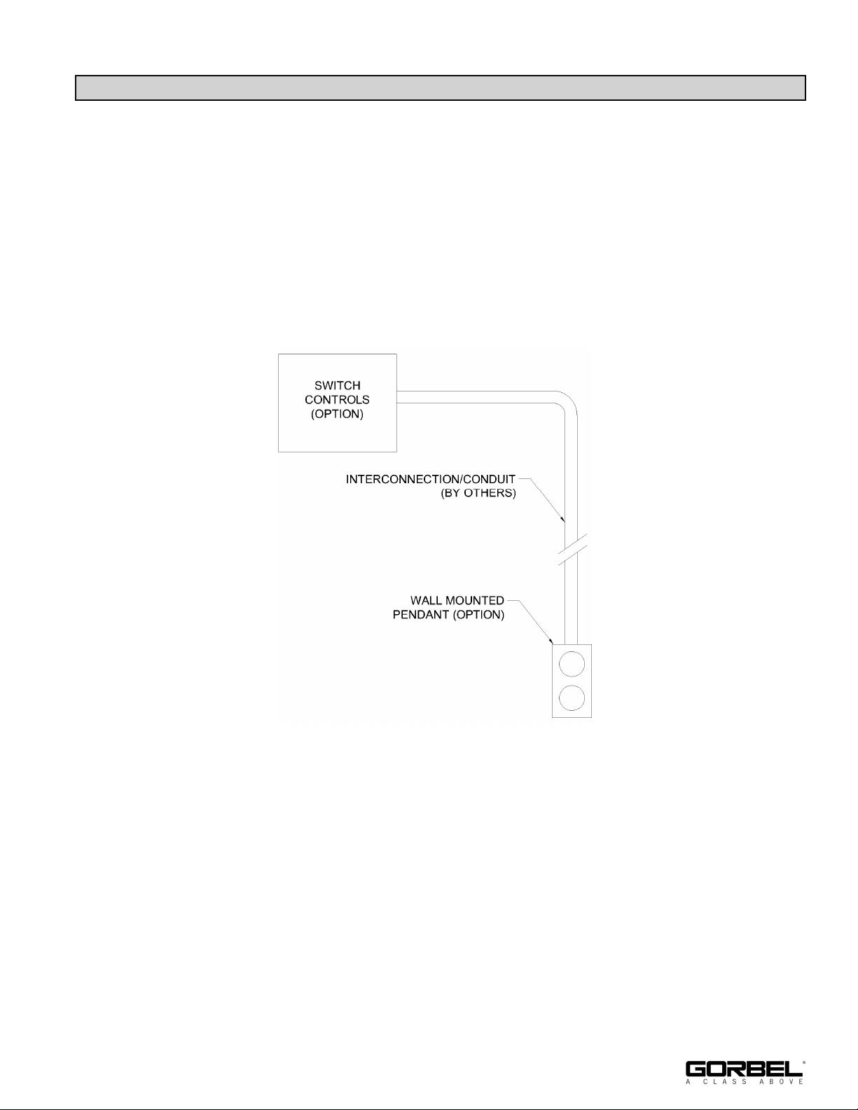
STEP 5 - CONTROL ENCLOSURE (OPTION)
Note: 208/230 VAC 3 phase 60 Hz or 460, 575 VAC 3 phase 60 Hz offered as standard. Control
voltage is 120 VAC, if supplied by Gorbel. Controls are factory set. Do not adjust without consulting factory.
5.1 Refer to wiring diagrams. See Appendix B on pages 15-18.
5.2
Punch/drill enclosure and wire per code. If SAFPOWRBAR® is used, power for the controls
can be tapped off jumper harness.
5.3 Refer to appropriate wiring diagram in appendix for operator interface to control panel. Wall
mounted pendant option is available upon request.
11/2018
Diagram 5A. Control Pendant.
7
Page 12
STEP 6 - MOTORIZED OPERATOR (OPTION)
6.1 Traversing speed is fixed and not adjustable.
6.2 Always verify:
• Incoming power phases are wired correctly
• Motor turns in correct direction
• Limit switches stop motor
It may be necessary to swap two legs of wiring if motor runs in reverse.
WARNING
Running motor in reverse direction may cause permanent damage to clutch/motor/controls, therefore
voiding warranty.
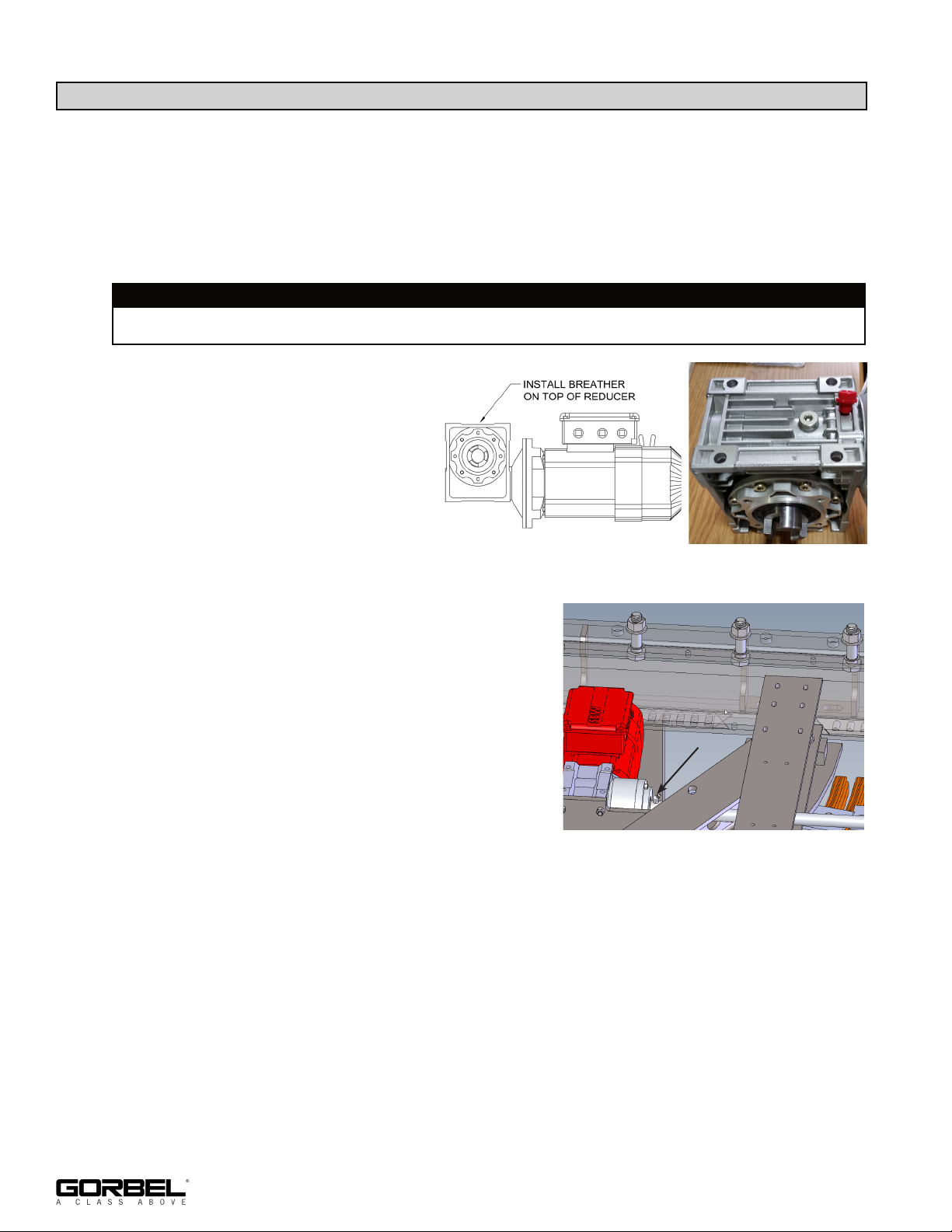
6.3 Install breather on reducer (diagram
6A).
6.4 Reducer comes filled with oil from
factory which should not need to be
changed over the life of the unit. In the
event of spillage or other condition
where addition of oil is necessary,
use synthetic gear oil, ISO 320 grade
(Mobil Glygoyle 30 or similar).
Diagram 6A. Installing breather on top of reducer.
6.5 Lubricate ball screw periodically (once per year or
every 10,000 actuations) (diagram 6B).
6.6 Limit switches and end stops are set at the factory.
Some field adjustment may be required for proper
rail alignment. See Step 6.7 on page 9 for
instructions.
Diagram 6B. Ball screw location.
8
11/2018
Page 13
STEP 6 - MOTORIZED OPERATOR (OPTION) (CONTINUED)
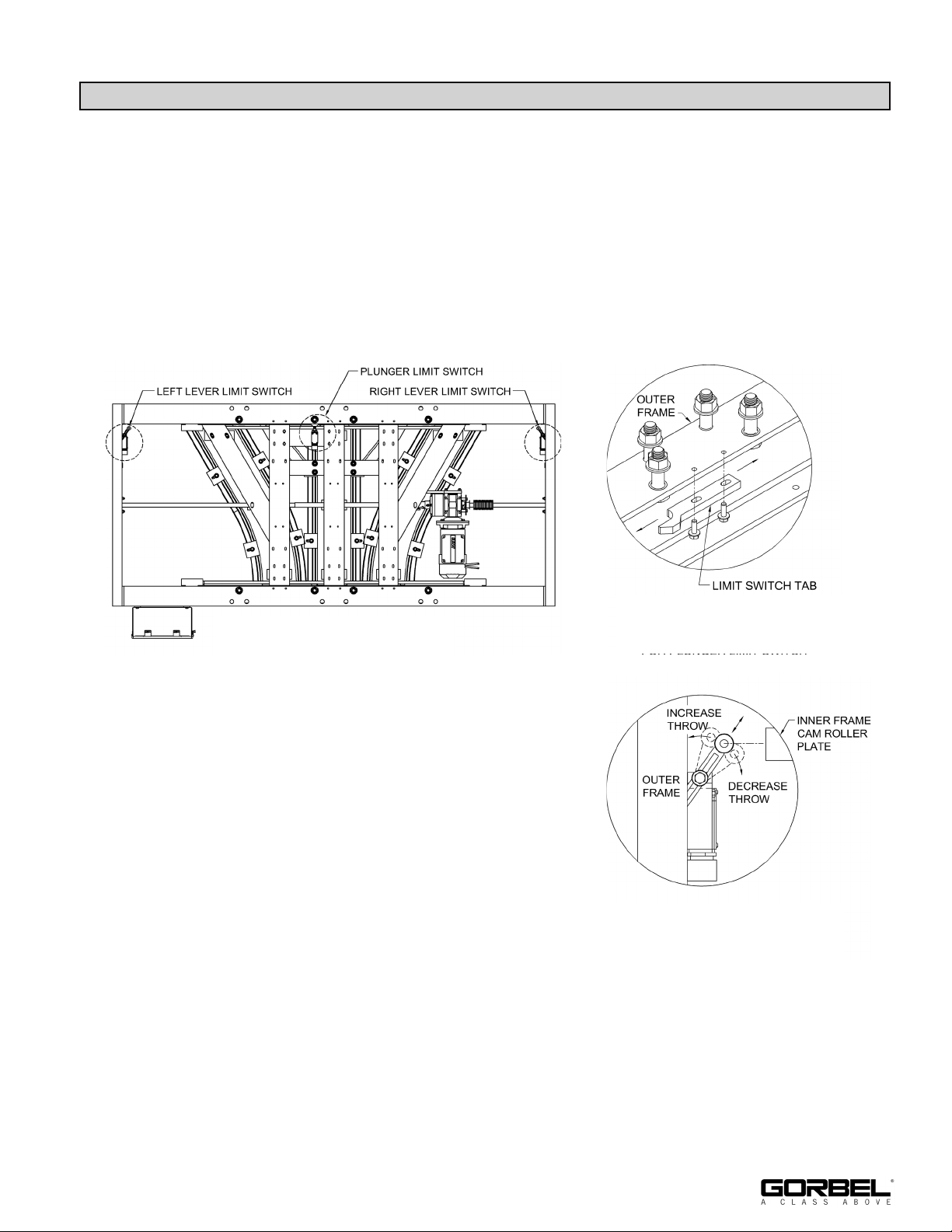
6.7 Adjusting limit switches:
1. Locate limit switches. See diagram 6C (3-way switch shown).
2. Adjust the middle (plunger) limit switch first for 3-Way only (skip to step 3 for 2-Way
motorized switches).
a. See diagram 6D. Loosen both screws holding the limit
switch tab in place.
b. Shift limit switch tab so that the inner frame rail is
centered on outer frame and lined up with incoming and
outgoing Tarca® rails.
c. Tighten limit switch tab screws.
Diagram 6C. 3 Way Switch - Limit
Switch Locations
3. Adjust left lever limit switch. See diagram 6E.
a. Loosen limit switch lever bolt.
b. Adjust limit switch lever until inner frame stops
in correct position (rails are aligned).
c. Tighten limit switch lever bolt.
d. Adjust stop bolt (not shown) so it touches inner
frame cam roller plate.
4. Adjust right lever limit switch.
a. Repeat step 3.
6.8 Overrun clutch is factory set and not adjustable.
Diagram 6D. Limit switch tab for
plunger limit switch
(on 3 Way Switch only)
Diagram 6E. Lever Limit Switch
Left - Shown
Right - Opposite
11/2018
9
Page 14
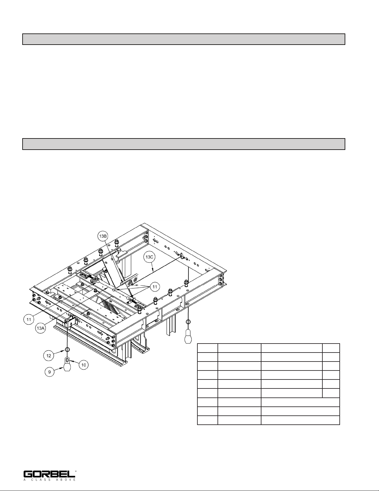
STEP 7 - PNEUMATIC OPERATOR (OPTION)
7.1 Route 1/4” NPT air hose (by others) to inlet of FR. 80-120 psi supply required. 1.2 CFM
maximum consumption. Regulator and controls are factory set. Do not adjust without
consulting factory.
STEP 8 - MANUAL OPERATOR (OPTION)
8.1 Cut chains to desired height and install handles using included chain connectors.
Standard drop is 20 ft. If more drop is required, remove handle and splice in new chain
with chain link.
8.2 Outriggers are available as options through Application Engineering. Consult factory for
information.
Diagram 8A. Pull chain diagram.
No. Part Number Description Qty
9 2-02174-000 Handle 2
10 2-02176-100 Chain Link 2
11 94298 Shackle 4
12 1-05772-000 Limit Ring 2
13 2-02176-000 Chain - Total Length 50 ft
13A - Cut to 16” Long
13B - Cut to 12” Long
13C - Leftover 47’-8”
10
11/2018
Page 15
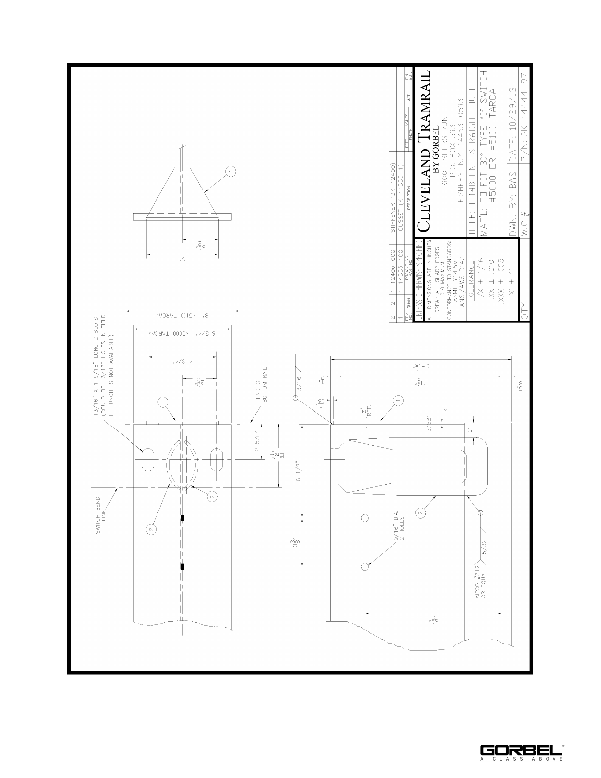
APPENDIX A - BEAM END PREP DIAGRAMS
11/2018
11
Page 16
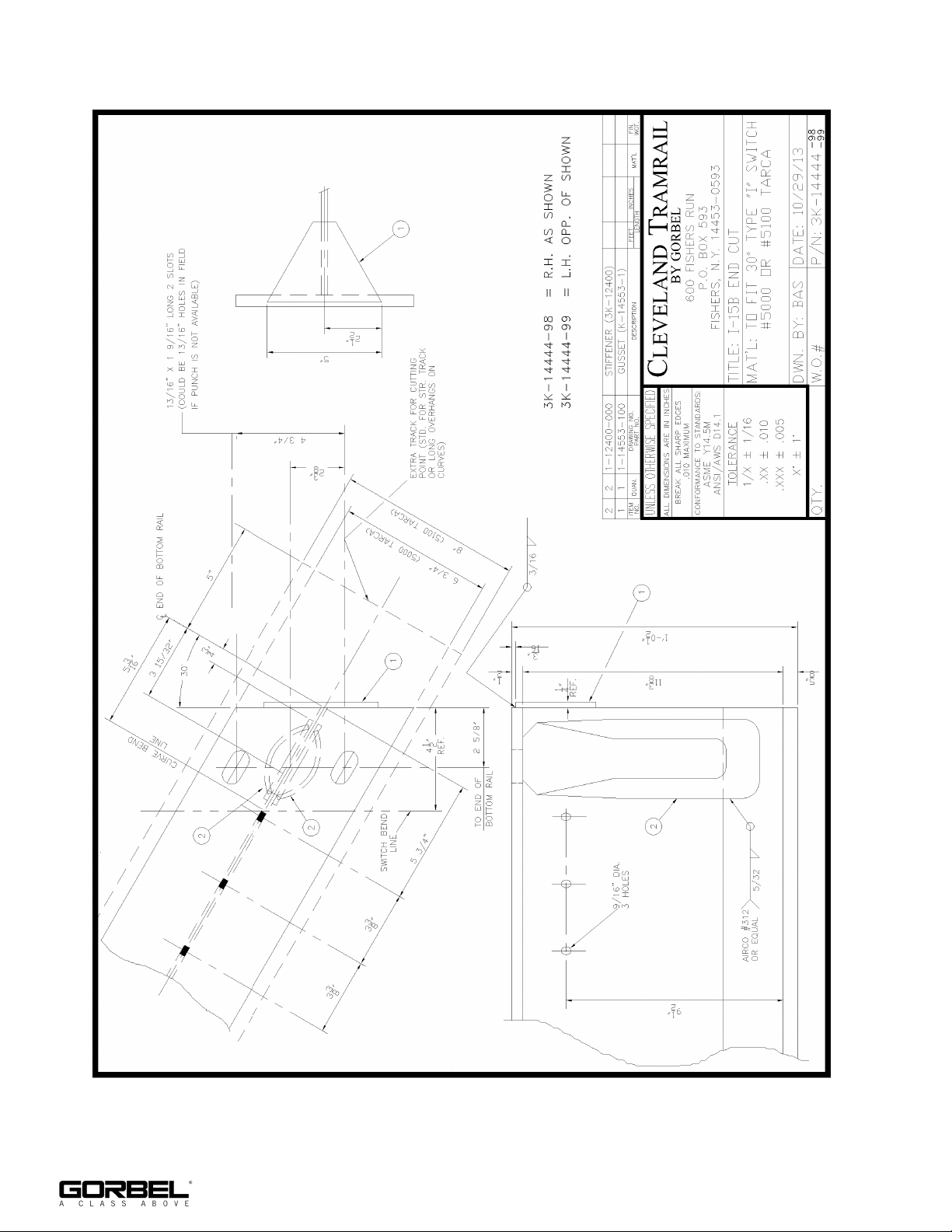
APPENDIX A - BEAM END PREP DIAGRAMS (CONTINUED)
12
11/2018
Page 17
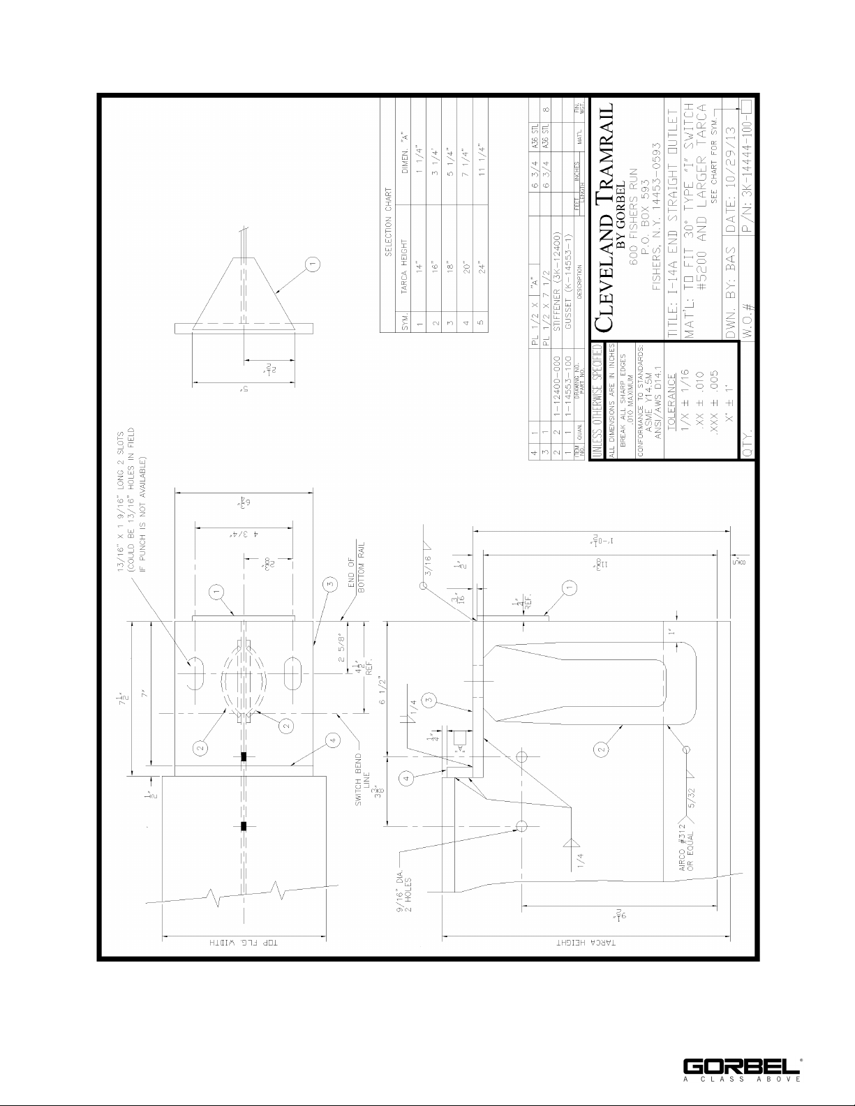
APPENDIX A - BEAM END PREP DIAGRAMS (CONTINUED)
11/2018
13
Page 18
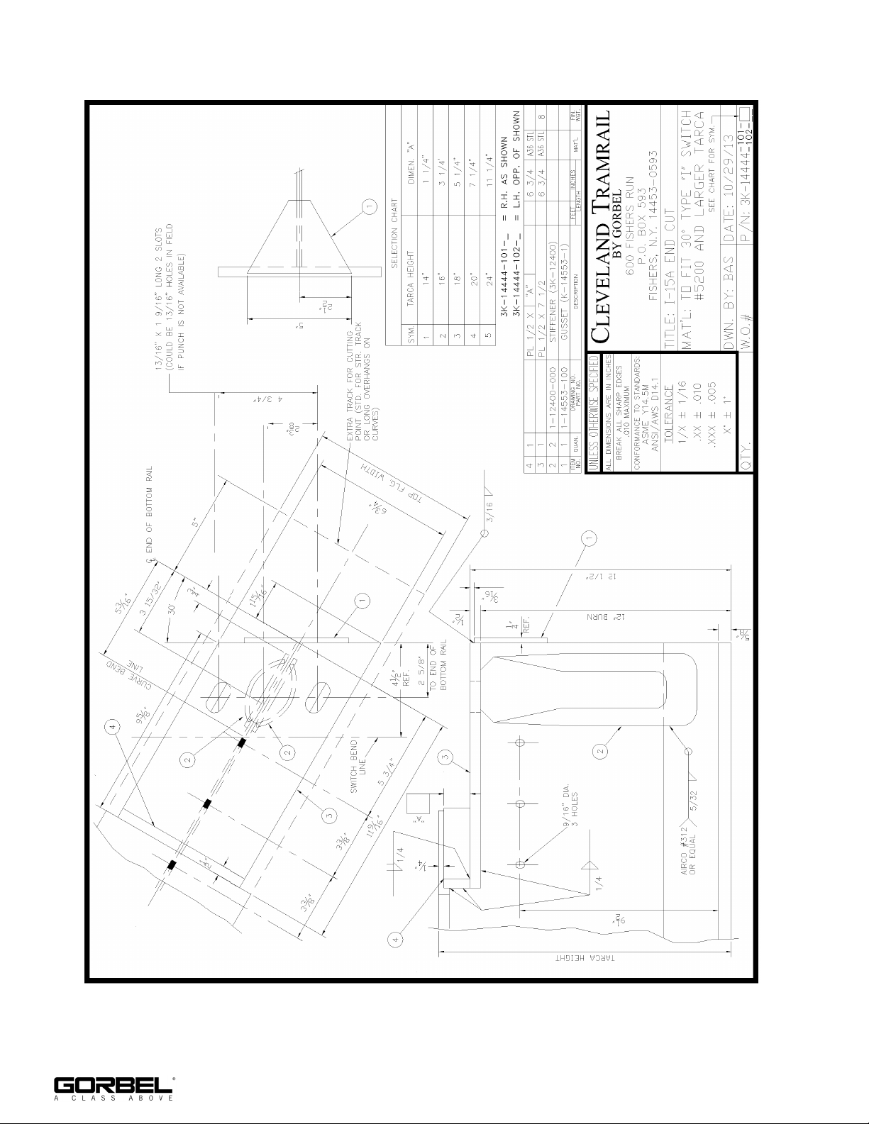
APPENDIX A - BEAM END PREP DIAGRAMS (CONTINUED)
14
11/2018
Page 19
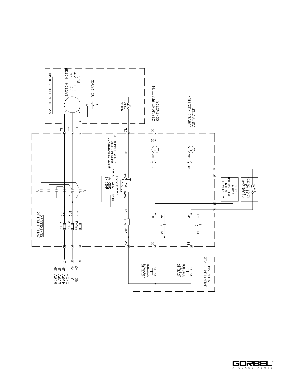
APPENDIX B - WIRING DIAGRAMS
11/2018
2-Way Motorized Schematic
15
Page 20
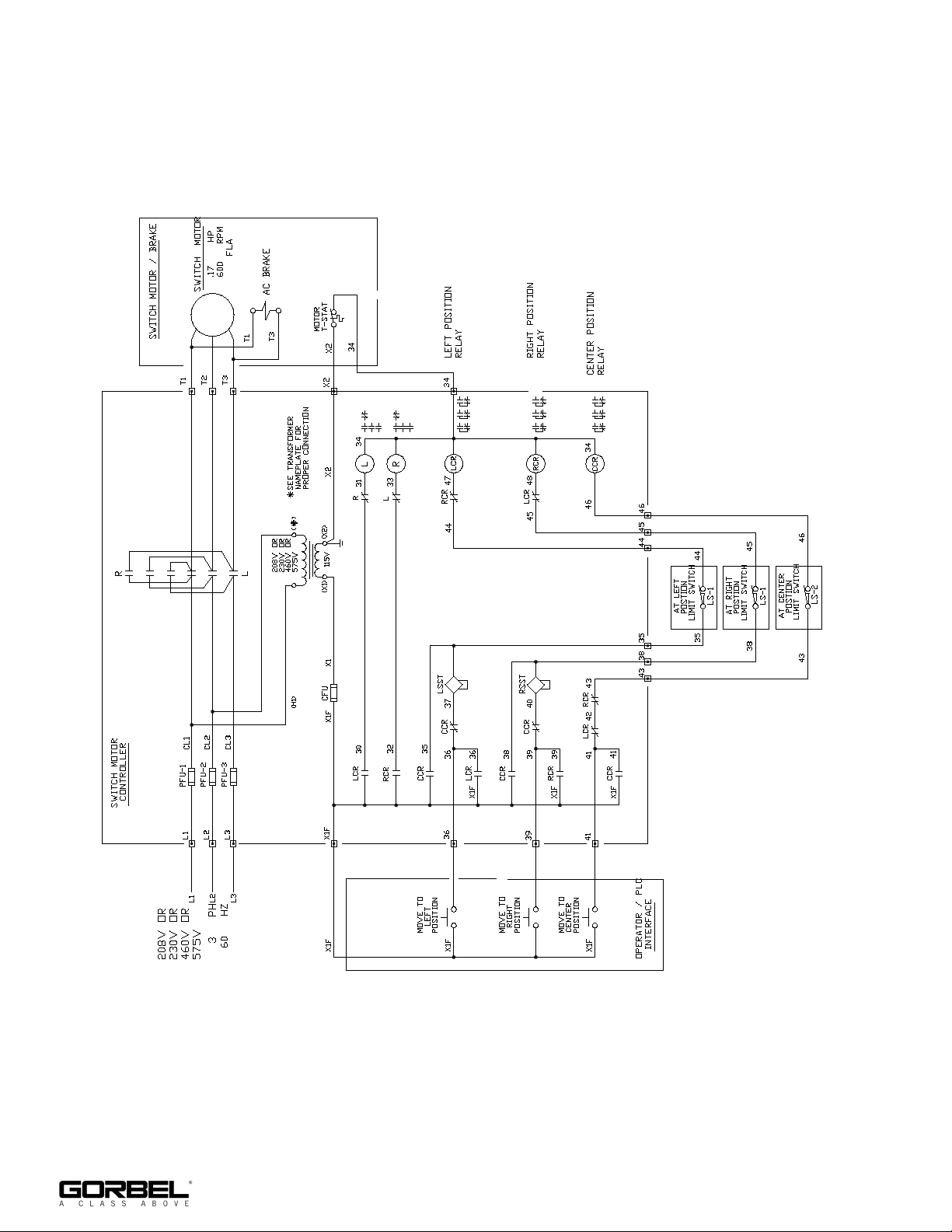
APPENDIX B - WIRING DIAGRAMS (CONTINUED)
3-Way Motorized Schematic
16
11/2018
Page 21
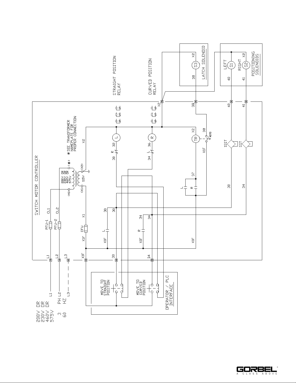
APPENDIX B - WIRING DIAGRAMS (CONTINUED)
11/2018
2-Way Pneumatic Schematic
17
Page 22
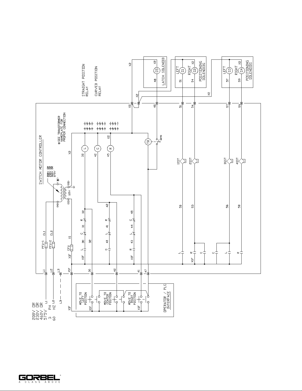
APPENDIX B - WIRING DIAGRAMS (CONTINUED)
3-Way Pneumatic Schematic
18
11/2018
Page 23

CRANE OPERATOR INSTRUCTIONS
Overhead Patented Track cranes generally handle materials over working areas where there are personnel. Therefore, it is important for the Crane Operator to be
instructed in the use of the crane and to understand the severe consequences of careless operation. It is not intended that these suggestions take precedence over
existing plant safety rules and regulations or OSHA regulations. However, a thorough study of the following information should provide a better understanding of safe
operation and afford a greater margin of safety for people and machinery on the plant floor. It must be recognized that these are suggestions for the Crane Operator’s
use. It is the responsibility of the owner to make personnel aware of all federal, state and local rules and codes, and to make certain operators are properly trained.
Qualifications
Crane operation, to be safe and efficient, requires skill: the exercise of extreme care and good judgement, alertness and concentration, and rigid adherence to proven
safety rules and practices as outlined in applicable and current ANSI and OSHA safety standards. In general practice, no person should be permitted to operate a
crane:
• Who cannot speak the appropriate language or read and understand the printed instructions.
• Who is not of legal age to operate this type of equipment.
• Whose hearing or eyesight is impaired (unless suitably corrected with good depth perception).
• Who may be suffering from heart or other ailments which might interfere with the operator’s safe performance.
• Unless the operator has carefully read and studied this operation manual.
• Unless the operator has been properly instructed.
• Unless the operator has demonstrated his instructions through practical operation.
• Unless the operator is familiar with hitching equipment and safe hitching equipment practices.
Handling the Trolley Motion
Before a load is handled, the hoist should be positioned directly over the load that is to be handled. When the slack is taken out of the slings, if the hoist is not directly
over the load, bring it directly over the load before hoisting is continued. Failure to center the hoist over the load may cause the load to swing upon lifting. Always
start the trolley motion slowly and reduce the trolley speed gradually.
Handling the Hoist Motion
Refer to the lifting (hoist) equipment’s operating instructions.
GENERAL SUGGESTIONS
Know Your Crane
Crane operators should be familiar with the principal parts of a crane and have a thorough knowledge of crane control functions and movements. The crane operator
should be required to know the location and proper operation of the main conductor disconnecting means for all power to the attachments on the crane.
Responsibility
Each crane operator should be held directly responsible for the safe operation of the crane. Whenever there is any doubt as to SAFETY, the crane operator should
stop the crane and refuse to handle loads until: (1) safety has been assured or (2) the operator has been ordered to proceed by the supervisor, who then assumes all
responsibility for the SAFETY of the lift.
Do not permit ANYONE to ride on the hook or a load.
Inspection
Test the crane movement and any attachments on the crane at the beginning of each shift. Whenever the operator finds anything wrong or apparently wrong, the
problem should be reported immediately to the proper supervisor and appropriate corrective action taken.
Operating Suggestions
One measure of a good crane operator is the smoothness of the crane operation. The good crane operator should know and follow these proven suggestions for
safe, efficient crane handling.
1. The crane should be moved smoothly and gradually to avoid abrupt, jerky movements of the load. Slack must be removed from the sling and hoisting ropes
before the load is lifted.
2. Center the crane over the load before starting the hoist to avoid swinging the load as the lift is started. Loads should not be swung by the crane to reach areas
not under the crane.
3. Crane-hoisting ropes should be kept vertical. Cranes shall not be used for side pulls.
4. Be sure everyone in the immediate area is clear of the load and aware that a load is being moved.
5. Do not make lifts beyond the rated load capacity of the crane, sling chains, rope slings, etc.
6. Make certain that before moving the load, load slings, load chains, or other lifting devices are fully seated in the saddle of the hook with hook latch closed (if
equipped with hook latch).
7. Check the be sure that the load and/or bottom block is lifted high enough to clear all obstructions when moving boom or trolley.
8. At no time should a load be left suspended from the crane unless the operator has the push button with the power on, and under this condition keep the load as
close as possible to the floor to minimize the possibility of an injury if the load should drop. When the crane is holding a load, the crane operator should remain
at the push button.
9. Do not lift loads with sling hooks hanging loose. If all sling hooks are not needed, they should be properly stored, or use a different sling.
10. All slings or cables should be removed from the crane hooks when not in use (dangling cables or hooks hung in sling rings can inadvertently snag other objects
when the crane is moving).
11. Operators shall not carry loads and/or empty bottom blocks over personnel. Particular additional caution should be practiced when using magnet or vacuum
devices. Loads, or parts of loads, held magnetically could drop. Failure of power to magnets or vacuum devices can result in dropping the load. Extra
precaution should be exercised when handling molten metal in the proximity of personnel.
12. Whenever the operator leaves the crane the following procedure should be followed:
• Raise all hooks to an intermediate position.
• Spot the crane at an approved designated location.
• Place all controls in the “off” position.
• Open the main switch to the “off” position.
• Make visual check before leaving the crane.
13. In case of emergency or during inspection, repairing, cleaning or lubrication, a warning sign or signal should be displayed and the main switch should be locked
in the “off” position. This should be done whether the work is being done by the crane operator or by others.
14. Contact with rotation stops or trolley end stops shall be made with extreme caution. The operator should do so with particular care for the safety of persons
below the crane, and only after making certain that any persons on the other cranes are aware of what is being done.
15. ANY SAFETY FEATURES AND MECHANISMS BUILT IN OR OTHERWISE PROVIDED WITH THE CRANE BY CLEVELAND TRAMRAIL ARE REQUIRED
FOR THE SAFE OPERATION OF THE CRANE. DO NOT, UNDER ANY CIRCUMSTANCES, REMOVE OR OTHERWISE IMPAIR OR DISABLE THE PROPER
FUNCTIONING OF ANY CRANE SAFETY MECHANISMS OR FEATURES BUILT-IN OR OTHERWISE PROVIDED BY CLEVELAND TRAMRAIL FOR SAFE
OPERATION OF THE CRANE. ANY REMOVAL, IMPAIRMENT OR DISABLING OF ANY SUCH SAFETY MECHANISMS OR FEATURES OR OTHER USE
OR OPERATION OF THE CRANE WITHOUT THE COMPLETE AND PROPER FUNCTIONING OF ANY SUCH SAFETY MECHANISMS OR FEATURES
AUTOMATICALLY AND IMMEDIATELY VOIDS ANY AND ALL EXPRESS AND IMPLIED WARRANTIES OF ANY KIND OR NATURE.
11/2018
19
Page 24

LIMITED WARRANTY
It is agreed that the equipment purchased hereunder is subject to the following LIMITED warranty and no other. Gorbel warrants the manual or motorized Patented
Track Crane products to be free from defects in material or workmanship for a period of two years or 4,000 hours use from date of shipment in class C service. This
warranty shall not cover failure or defective operation caused by operation in excess of recommended capacities, misuses, negligence or accident, and alteration or
repair not authorized by Gorbel. No system shall be modified after manufacture without the written authorization of Cleveland Tramrail Inc. Any field modification
without the written authorization of Gorbel Inc. shall void Gorbel’s warranty obligation. This warranty shall not cover wearable parts, including but not limited to wheels,
gears, pinions, bearings, motors, electrical controls, and crane electrification. OTHER THAN AS SET FORTH HEREIN, NO OTHER EXPRESS WARRANTIES, AND
NO IMPLIED WARRANTIES, ORAL OR WRITTEN, INCLUDING BUT NOT LIMITED TO THE WARRANTIES OF MERCHANTABILITY OR FITNESS FOR A
PARTICULAR PURPOSE, ARE MADE BY GORBEL WITH RESPECT TO ITS PRODUCTS AND ALL SUCH WARRANTIES ARE HEREBY SPECIFICALLY
DISCLAIMED. GORBEL SHALL NOT BE LIABLE UNDER ANY CIRCUMSTANCES FOR ANY INCIDENTAL, SPECIAL, AND/OR CONSEQUENTIAL DAMAGES
WHATSOEVER, WHETHER OR NOT FORESEEABLE, INCLUDING BUT NOT LIMITED TO DAMAGES FOR LOST PROFITS AND ALL SUCH INCIDENTAL,
SPECIAL, AND/OR CONSEQUENTIAL DAMAGES ARE HEREBY ALSO SPECIFICALLY DISCLAIMED. Gorbel’s obligation and Purchaser’s or end user’s sole
remedy under this warranty is limited to the replacement or repair of Gorbel’s products at the factory, or at the discretion of Gorbel, at a location designated by Gorbel.
Purchaser or end user shall be solely responsible for all freight and transportation costs incurred in connection with any warranty work provided by Gorbel hereunder.
Gorbel will not be liable for any loss, injury or damage to persons or property, nor for damages of any kind resulting from failure or defective operation of any
materials or equipment furnished hereunder. Components and accessories not manufactured by Gorbel are not included in this warranty. Purchaser’s or end user’s
remedy for components and accessories not manufactured by Gorbel is limited to and determined by the terms and conditions of the warranty provided by the respective manufacturers of such components and accessories.
A) DISCLAIMER OF IMPLIED WARRANTY OF MERCHANTABILITY
Gorbel and Purchaser agree that the implied warranty of merchantability is excluded from this transaction and shall not apply to the goods
involved in this transaction.
B) DISCLAIMER OF IMPLIED WARRANTY OF FITNESS FOR PARTICULAR PURPOSE
Gorbel and Purchaser agree that the implied warranty of fitness for particular purpose is excluded from this transaction and shall not apply to
the goods involved in this transaction.
C) DISCLAIMER OF EXPRESS WARRANTY
Gorbel’s agents, or dealer’s agents, or distributor’s agents may have made oral statements about the machinery and equipment described in
this transaction. Such statements do not constitute warranties, and Purchaser agrees not to rely on such statements. Purchaser also agrees
that such statements are not part of this transaction.
D) DISCLAIMER OF SPECIAL, INCIDENTAL AND CONSEQUENTIAL DAMAGES
Gorbel and Purchaser agree that any claim made by Purchaser which is inconsistent with Gorbel’s obligations and the warranty remedies
provided with Gorbel’s products, and in particular, special, incidental and consequential damages, are expressly excluded.
E) DEALER OR DISTRIBUTOR NOT AN AGENT
Gorbel and Purchaser agree that Purchaser has been put on notice that dealer or distributor is not Gorbel’s agent in any respect for any
reason. Gorbel and Purchaser also agree that Purchaser has been put on notice that dealer or distributor is not authorized to incur any
obligations or to make any representations or warranties on Gorbel’s behalf other than those specifically set forth in Gorbel’s warranty provided
in connection with its product.
F) MERGER
This warranty agreement constitutes a final and complete written expression of all the terms and conditions of this warranty and is a complete
and exclusive statement of those terms.
G) PAINTING
Every crane (excluding components) receives a quality paint job before leaving the factory. Unfortunately, no paint will protect against the
abuses received during the transportation process via common carrier. We have included at least one (1) twelve ounce spray can for touchup
with each crane ordered (unless special paint was specified). If additional paint is required, contact a Gorbel® Inside Sales Representative at
1-800-821-0086 or 1-585-924-6262.
Title and Ownership:
Title to the machinery and equipment described in the foregoing proposal shall remain with Gorbel and shall not pass to the Purchaser until the full amount
herein agreed to be paid has been fully paid in cash.
Claims and Damages:
Unless expressly stated in writing, goods and equipment shall be at Purchaser’s risk on and after Seller’s delivery in good shipping order to the Carrier.
Gorbel shall in no event be held responsible for materials furnished or work performed by any person other than it or its authorized representative or agent.
Cancellations:
If it becomes necessary for the Purchaser to cancel this order wholly or in part, he shall at once so advise Gorbel in writing. Upon receipt of such written notice
all work will stop immediately. If the order entails only stock items, a flat restocking charge of 15% of the purchase price will become due and payable by
Purchaser to Gorbel. Items purchased specifically for the canceled order shall be charged for in accordance with the cancellation charges of our supplier plus
15% for handling in our factory. The cost of material and/or labor expended in general fabrication for the order shall be charged for on the basis of total costs to
Gorbel up to the time of cancellation plus 15%.
Returns:
No equipment, materials or parts may be returned to Gorbel without express permission in writing to do so.
Extra Charge Delay: If Purchaser delays or interrupts progress of Seller’s performance, or causes changes to be made, Purchaser agrees to reimburse Gorbel
for expense, if any, incident to such delay.
Changes and Alterations:
Gorbel reserves the right to make changes in the details of construction of the equipment, as in its judgement, will be in the interest of the Purchaser; will make
any changes in or additions to the equipment which may be agreed upon in writing by the Purchaser; and Gorbel is not obligated to make such changes in
products previously sold any customer.
Third Party Action:
Should Gorbel have to resort to third party action to collect any amount due after thirty (30) days from the date of invoice, the Purchaser agrees to pay collection
costs, reasonable attorney’s fees, court costs and legal interest.
OSHA Responsibilities:
Gorbel agrees to fully cooperate with Purchaser in the design, manufacture or procurement of safety features or devices that comply with OSHA regulations. In
the event additional equipment or labor shall be furnished by Gorbel, it will be at prices and standard rates then in effect, or as may be mutually agreed upon at
the time of the additional installation.
Equal Employment Opportunity:
Gorbel agrees to take affirmative action to ensure equal employment opportunity for all job applicants and employees without regard to race, color, age, religion,
sex, national origin, handicap, veteran, or marital status. Gorbel agrees to maintain non-segregated work facilities and comply to rules and regulations of the
Secretary of Labor or as otherwise provided by law or Executive Order.
20
11/2018
Page 25

PERIODIC INSPECTION AND LUBRICATION RECOMMENDATIONS
The following is a checklist to be followed in performing periodic inspections and preventative
maintenance on Gorbel® Tarca® Systems. It is intended that this checklist be supplemented with
any additional instruction sheets and maintenance manuals sent with each job.
The frequency of inspection and lubrication recommendations presented herein is based upon
normal operating conditions of one complete handling cycle every 10 minutes throughout a
40-hour week. If the actual duty cycle of a particular unit is greater or less than this, the inspections and lubrications should be performed more frequently or less frequently in proportion.
Each industry has conditions peculiar to it, which may cause wear of certain parts. The tabulation
given is only general and may be supplemented by an individual maintenance department
program to meet its own particular requirements. Particular attention should be given to corrosive
conditions, excessive vibrations, extreme ambient temperature variations, and rough handling
conditions.
Questions regarding damaged, worn or cracked equipment components should be directed to
the Gorbel® Customer Service Department at 800-821-0086 or 585-924-6262.
The recommendations contained herein are to be supplemented by any vendor instructions,
which are included in this manual.
WARNING: Power should be off and locked when performing maintenance on any part of the
system.
* State and local codes may require inspection and maintenance checks more often. Please
check the state and local code manuals in your area.
TRACK SWITCHES
COMPONENT MAINTENANCE FREQUENCY
Outer Frame
Inner Frame
Slides or Rollers
Jumper Harness Check for loose or corroded connections or abrasion.
Grounds
Track
Electrical
Rubber Bumper Check for loose bolts and for incipient cracks.
Check for loose support bolts and levelness of frame in both directions.
Check for excessive wear at latch holes or on latch cams.
Check rollers (should not rock with level outer frame). Check latch pin or
rollers for full and positive engagement. Make sure operator fasteners
are tight and in proper position. Check crank and fasteners for wear and
proper tightness.
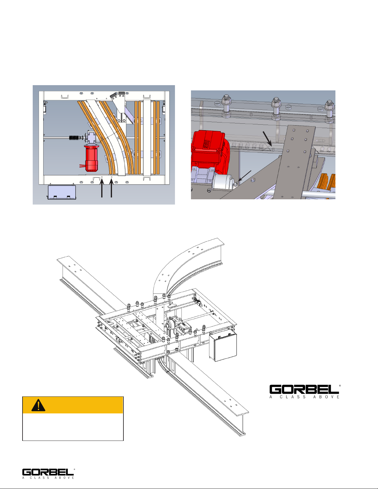
Clean and perform maintenance greasing of grease fittings with any general purpose grease. Refer to figure 1 on page 24 for position of fittings.
Check for continuity.
Check for worn ends. Check for raised tread. Check for track width.
Check for cracked welds. Replace track or switch if badly worn. Check
alignment at rail gaps. Should be within 0-1/32” vertically and +/- 1/16”
horizontally. If realignment is necessary, adjust throw first then shim and
align adjacent rails.
Check control panel and/or junction box terminals. Check contacts.
Tighten loose screws.
Every 2,000 hours
or yearly
Every 2,000 hours
or yearly
Every 2,000 hours
or yearly
Every 2,000 hours
or yearly
Every 2,000 hours
or yearly
Every 2,000 hours
or yearly
Every 2,000 hours
or yearly
Every 1,000 hours
or every 6 months
11/2018
21
Page 26
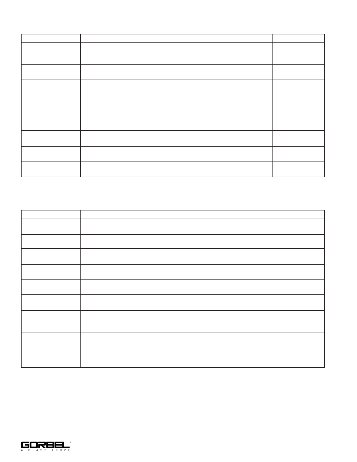
TRACKS, RUNWAYS & HANGERS
COMPONENT MAINTENANCE FREQUENCY
Top Hanger Bracket/
Beam Clips/
Threaded Rod
Lower Hanger
Bracket
Sway Brace
Connection
Track
Joints
End Stops Check for loose bolts and for incipient cracks.
Paint Clean periodically and repaint where corrosion is present.
Check that lock washers are compressed and nuts tightened to
manufacturer’s specifications.
Check that lock washers are compressed and nuts tightened to
manufacturer’s specifications.
Check for loose bolts & cracked fittings.
Check for rail wear (replace if raised portion of tread is gone). Check
welds for incipient cracks. Check underside of rail for wear from drive
rollers if using tractor drives. When groove is 1/8” deep, replace track.
Check side of rail for wear. When width has decreased more than 1/8”,
replace track.
Check for loose or worn hardware or if welded type, for incipient cracks.
Check for track alignment and that wheel rolling surface is flush.
Every 1,000 hours
or 6 months
Every 1,000 hours
or 6 months
Every 1,000 hours
or 6 months
Every 2,000 hours
or yearly
Every 2,000 hours
or yearly
Every 2,000 hours
or yearly
Every 2,000 hours
or yearly
SAFPOWRBAR® CONDUCTOR BAR
COMPONENT MAINTENANCE FREQUENCY
Bar
Couplings
Supports Check for loose bolts and/or screws and bent brackets.
Insulators
Bar Covering Check for accidental abrasion and peeled covering.
Current Taps
Grounds
Collectors
Check for corrosion, bowing, or sagging. Check alignment at moving
gaps. Realign if necessary.
Check bolt or screw tightness. Check for corroded contact
surfaces.
Check for loose bolts, sheared support ears, current carrying deposits on
surface.
Check bolt and terminal screw tightness. Check for corroded contact
surface.
Check for ground continuity. Check at load side of disconnect switch
(current off), with meg-ohm tester, for overall system insulation
resistance.
Check for worn shoes. Check flexible leads from wheel clevis pigtail or
slide shoe shaft. Check tightness of lead connections. Check for cracked
insulators. On type “ST” collectors, check for free movement or
pantograph. Lubricate pivot pins as required. Collector bracket tubes
should be vertical within 1/16”. Replace if necessary.
Every 2,000 hours
or yearly
Every 2,000 hours
or yearly
Every 2,000 hours
or yearly
Every 2,000 hours
or yearly
Every 2,000 hours
or yearly
Every 2,000 hours
or yearly
Every 2,000 hours
or yearly
Every 750 hours
or 4 months
22
11/2018
Page 27

TROLLEY & CARRIERS
COMPONENT MAINTENANCE FREQUENCY
Structural Frame &
Load Bars
Eye Bolts,
Suspension Pins &
Ball Joint Rocker
Assembly
Wheels & Guide
Rollers
Check for incipient cracks in welds and castings. Check for loose bolts.
Check for loose or missing set screws or lock pins. Grease spherical
bearing housing monthly through grease fitting or repack with clean
grease at three (3) month intervals. Use Calcium Sulfonate type grease
(Peerless OG2 Red or equal). Check for cracks and excessive wear.
Note: When lubricating through grease fitting or repacking, suspension
pins and ball joint rocker assembly should be raised approximately 1/4”.
Check for loose wheel bearings. Check wheels for proper contact and
tracking on rail. Check wheel diameter for wear (replace when 1/4” under
original diameter). Check axle nuts for tightness. Lubricate using Calcium
Sulfonate type grease (Peerless OG2 Red or equal).
Every 2,000 hours
or yearly
Every 150 hours or
1 month
Every 500 hours or
3 months
Check oil level. Change oil as ambient temperature requires (see Lube
Geared Drive
Belt Drive Check for belt wear
Motors
Control
Electric Brakes
(Disc)
Head Check for thrust washer wear and integrity.
List). Check gear wear through backlash. Check for worn bearings
(excessive noise). Check for loose bolts in gear case cover.
Check motor after active use for excessive heat (130° C or 226° F max.
with class “B” insulation). Check motor bearings and oil seals. Tighten
loose bolts. Blow out dust. Lubricate. Also see motor manufacturer’s
recommendations.
Check for burned contacts. Check mechanical latch devices for wear and
freedom of movement. Check for loose connections.
Adjust air gap for wear. Check lining thickness. Check for broken
shading coils. Check rotating disc at spline for excessive wear. See
manufacturer’s recommendations.
HOIST (Refer to Hoist Manufacturer)
Every 750 hours or
4 months
Every 750 hours or
4 months
Every 1,000 hours
or 6 months
Every 1,000 hours
or 6 months
Every 750 hours or
4 months
Every 1,000 hours
or 6 months
11/2018
23
Page 28
RECOMMENDED LUBRICANT LIST
WARNING
This produc
,
which are
more inf
Mobilith SHC PM 460 grease or equivalent for ball screw (if motorized).
Multi-purpose grease for rollers (same grease as ball screw is acceptable).
Light tool oil for locking mechanism (if manual or pneumatic).
Pneumatic oil for FRL (if pneumatic).
Figure 1
t can expose you to chemicals, including acrylonitrile
known to the State of California to cause cancer. For
ormation go to:
www.P65Warnings.ca.gov
600 Fishers Run, P.O. Box 593
Fishers, NY 14453-0593
Phone: (800) 821-0086
Fax: (800) 828-1808
E-Mail: [email protected]
http://www.gorbel.com
©2018 Gorbel, Inc.
All Rights Reserved
24
11/2018
 Loading...