

GORBEL 150 BX G-Force, 380 BX G-Force, 300 BX G-Force Installation, Operation & Maintenance Manual

IInnssttaallllaattiioonn,,
OOppeerraattiioonn,,
&& MMaaiinntteennaannccee
MMaannuuaall
U.S. PATENT NO’S:
5,865,426, 6,386,513,
& 6,886,812
OTHER PATENTS
PENDING
115500//330000//338800 llbbss..
BBXX SSeerriieess
Gorbel® Dealer:________________________________
Serial Number: _________________________________
Gorbel® Customer Order No.: ____________________
Date: _________________________________________
CAPACITY MAXIMUM
lbs.
150
®
™
™

TABLE OF CONTENTS
Safe Hoist Operating Guidelines . . . . . . . . . . . . . . . . . . . . . . . . . . . . . . . . . . . . . . . . . . . . . . . . . . . . . . . . . . . . . . . . . .2-4
Introduction . . . . . . . . . . . . . . . . . . . . . . . . . . . . . . . . . . . . . . . . . . . . . . . . . . . . . . . . . . . . . . . . . . . . . . . . . . . . . . . . . . . . .5
Correct G-Force® Installation Orientation . . . . . . . . . . . . . . . . . . . . . . . . . . . . . . . . . . . . . . . . . . . . . . . . . . . . . . . . . . . .6
G-Force® BX ILD Main Assembly Component Descriptions . . . . . . . . . . . . . . . . . . . . . . . . . . . . . . . . . . . . . . . . . . . . .6
Lift Functionality . . . . . . . . . . . . . . . . . . . . . . . . . . . . . . . . . . . . . . . . . . . . . . . . . . . . . . . . . . . . . . . . . . . . . . . . . . . . . . . .7-8
Controls Interface Features . . . . . . . . . . . . . . . . . . . . . . . . . . . . . . . . . . . . . . . . . . . . . . . . . . . . . . . . . . . . . . . . . . . . . . .8-9
Technical Specifications . . . . . . . . . . . . . . . . . . . . . . . . . . . . . . . . . . . . . . . . . . . . . . . . . . . . . . . . . . . . . . . . . . . . . . . . . .10
Installation
Step 1 - Unpacking the BX G-Force® ILD . . . . . . . . . . . . . . . . . . . . . . . . . . . . . . . . . . . . . . . . . . . . . . . . . . . . . . . . .11
Step 2 - Pre-assembly . . . . . . . . . . . . . . . . . . . . . . . . . . . . . . . . . . . . . . . . . . . . . . . . . . . . . . . . . . . . . . . . . . . . . . . .12
Step 3 - Handle-Coil Cord Installation (Standard Inline Units) . . . . . . . . . . . . . . . . . . . . . . . . . . . . . . . . . . . . . . .12-13
Step 3A - Handle-Coil Cord Installation (Remote Mount Standard Units) . . . . . . . . . . . . . . . . . . . . . . . . . . . . . . .13-14
Step 3B - Handle-Coil Cord Installation (Remote Mount Float Mode Units) . . . . . . . . . . . . . . . . . . . . . . . . . . . . .14-15
Step 4 - Installing the Actuator Assembly . . . . . . . . . . . . . . . . . . . . . . . . . . . . . . . . . . . . . . . . . . . . . . . . . . . . . . . . .15
Step 5 - Electrical Power Connection . . . . . . . . . . . . . . . . . . . . . . . . . . . . . . . . . . . . . . . . . . . . . . . . . . . . . . . . . .15-16
Step 6 - Air Connection (Option) . . . . . . . . . . . . . . . . . . . . . . . . . . . . . . . . . . . . . . . . . . . . . . . . . . . . . . . . . . . . . . . .16
Step 7 - Initial Power Up . . . . . . . . . . . . . . . . . . . . . . . . . . . . . . . . . . . . . . . . . . . . . . . . . . . . . . . . . . . . . . . . . . . . . .16
Step 8 - Adjusting Lift Speed . . . . . . . . . . . . . . . . . . . . . . . . . . . . . . . . . . . . . . . . . . . . . . . . . . . . . . . . . . . . . . . .16-17
Step 9 - Float Mode (Option) . . . . . . . . . . . . . . . . . . . . . . . . . . . . . . . . . . . . . . . . . . . . . . . . . . . . . . . . . . . . . . . . . . .17
Step 10 - Final Steps . . . . . . . . . . . . . . . . . . . . . . . . . . . . . . . . . . . . . . . . . . . . . . . . . . . . . . . . . . . . . . . . . . . . . . . . . .17
Drive Fault Troubleshooting Chart . . . . . . . . . . . . . . . . . . . . . . . . . . . . . . . . . . . . . . . . . . . . . . . . . . . . . . . . . . . . . . .17-18
Wire Rope Inspection, Maintenance, Replacement Criteria & Replacement Instructions . . . . . . . . . . . . . . . . . .19-23
Appendix A - 150# BX Actuator Assembly Drawings . . . . . . . . . . . . . . . . . . . . . . . . . . . . . . . . . . . . . . . . . . . . . . . .24-32
Appendix B - 300/380# BX Actuator Assembly Drawings . . . . . . . . . . . . . . . . . . . . . . . . . . . . . . . . . . . . . . . . . . . .33-41
Appendix C - BX Standard Handle Assembly Drawings . . . . . . . . . . . . . . . . . . . . . . . . . . . . . . . . . . . . . . . . . . . . .42-49
Appendix D - BX Float Mode Handle Assembly Drawings . . . . . . . . . . . . . . . . . . . . . . . . . . . . . . . . . . . . . . . . . . . .50-55
Appendix E - BX Coil Cord Assembly - Schematic Drawings . . . . . . . . . . . . . . . . . . . . . . . . . . . . . . . . . . . . . . . . .56-59
Appendix F - Controls Schematic Drawings . . . . . . . . . . . . . . . . . . . . . . . . . . . . . . . . . . . . . . . . . . . . . . . . . . . . . . .60-61
Appendix G - Overall G-Force® Reference Dimension Drawings . . . . . . . . . . . . . . . . . . . . . . . . . . . . . . . . . . . . . .62-63
Appendix H - BX G-Force® Handle Reference Dimension Drawings . . . . . . . . . . . . . . . . . . . . . . . . . . . . . . . . . . . . .64
Appendix I - Component Layout Drawings . . . . . . . . . . . . . . . . . . . . . . . . . . . . . . . . . . . . . . . . . . . . . . . . . . . . . . . .65-68
Recommended Spare Parts List . . . . . . . . . . . . . . . . . . . . . . . . . . . . . . . . . . . . . . . . . . . . . . . . . . . . . . . . . . . . . . . . . . . .69
Limited Warranty . . . . . . . . . . . . . . . . . . . . . . . . . . . . . . . . . . . . . . . . . . . . . . . . . . . . . . . . . . . . . . . . . . . . . . . . . . . . . . . .70
Inspection and Maintenance Schedule . . . . . . . . . . . . . . . . . . . . . . . . . . . . . . . . . . . . . . . . . . . . . . . . . . . . . . . . . . . . . .71
1
4/04-Rev. S
®

SAFE HOIST OPERATING GUIDELINES
General
There is no one single factor that is more important for minimizing
the possibility of personal injury to the operator and those working
in the area, or damage to property, equipment, or material, than
being familiar with the equipment and using Safe Operating
Practices.
Hoists/trolleys are designed for lifting and transporting of material
only. Under no circumstances, either during initial installation or in
any other use, should the hoist be used for lifting or transporting
personnel.
No operator should be permitted to use the equipment that is not
familiar with its operation, is not physically or mentally fit, or has
not been schooled in safe operating practices. The misuse of
hoists can lead to certain hazards which cannot be protected
against by mechanical means; hazards which can only be avoided
by the exercise of intelligence, care, and common sense.
Safe Operating Practices also involve a program of periodic
inspection and preventative maintenance (covered in separate
section). Part of the operator’s training should be an awareness of
potential malfunctions/hazards requiring adjustments or repairs,
and bringing these to the attention of supervision for corrective
action.
Supervision and management also have an important role to play
in any safety program by ensuring that a maintenance schedule is
adhered to, and that the equipment provided for the operators is
suitable for the job intended without violation of one or more of the
rules covering safe operating practices and good common sense.
The Safe Operating Practices shown are taken in part from the
following publications:
• American National Standard Institute (ANSI)
• Safety Standards for Crane, Derricks, Hoists
• ANSI B30.2 - Overhead and Gantry Cranes
• ANSI B30.16 - Overhead Hoist
Do’s and Don’ts (Safe Operation of Hoists)
The following are Do’s and Don’ts for safe operation of overhead
hoists. A few minutes spent reading these rules can make an
operator aware of dangerous practices to avoid and precautions to
take for his own safety and the safety of others. Frequent
examinations and periodic inspections of the equipment as well as
a conscientious observance of safety rules may save lives as well
as time and money.
DON’TS - HOISTS
1. Never lift or transport a load until all personnel are clear and
do not transport the load over personnel.
2. Do not allow any unqualified personnel to operate hoist.
3. Never pick up a load beyond the capacity rating appearing on
the hoist. Overloading can be caused by jerking as well as by
static overload.
4. Never carry personnel on the hook or the load.
5. Do not operate hoist if you are not physically fit.
6. Do not operate hoist to extreme limits of travel of cable
without first checking for proper limit switch action.
7. Avoid sharp contact between two hoists or between hoist and
end stops.
8. Do not tamper with or adjust any parts of the hoist unless
specifically authorized to do so.
9. Never use the load cable as a sling.
10. Do not divert attention from load while operating hoist.
11. Never leave a suspended load unattended.
12. Do not use limit switch(es) for normal operating stop(s).
These are safety devices only and should be checked on a
regular basis for proper operation.
13. Never operate a hoist that has an inherent or suspected
mechanical or electrical defect.
14. Do not use load cable as ground for welding. Never touch a
live welding electrode to the load cable.
15. Do not jog controls unnecessarily. Hoist motors are generally
high torque, high slip types. Each start causes an inrush of
current greater than the running current and leads to
overheating and heat failure, or burnout, if continued to excess.
16. Do not operate hoist if load is not centered under hoist.
17. Do not operate hoist if cable is twisted, kinked or damaged.
18. Do not remove or obscure label.
19. Do not permanently activate dead man’s switch.
DO’S - HOISTS
1. Read and follow manufacturer’s instruction, installation, and
maintenance manuals. When repairing or maintaining a hoist,
use only manufacturer’s recommended parts and materials.
2. Read and follow all instruction and warning information on or
attached to a hoist.
3. Remove the hoist from service and thoroughly inspect and
repair, as necessary, if unusual performance or visual defects
(such as peculiar noise, jerky operations, travel in improper
direction, or obviously damaged parts) are noticed.
4. Establish a regular schedule of inspection and maintain
records for all hoists with special attention given to hooks,
load cables, brakes, and limit switches.
5. Check operation of brakes for excessive drift.
6. Never lift loads over people, etc.
7. Check for damaged hooks and load cable.
8. Keep load cable clean and well maintained.
9. Check the load cable for improper seating, twisting, kinking,
wear, or other defects before operating the hoists.
10. Make sure a load clears neighboring stockpiles, machinery, or
other obstructions when raising, lowering, or traveling the load.
11. Center hoist over load before operating.
12. Avoid swinging of load or load hook when traveling the hoist.
13. Be sure the load attachment is properly seated in the saddle
of the hook. Balance load properly before handling. Avoid
hook tip loading.
14. Pull in a straight line, so that neither hoist body nor load cable
are angled around an object.
15. Take up slack slowly.
16. Know the hand signals for hoisting, cross travel, and crane
travel if working with cab-operated hoists or cranes.
Operators should accept the signals of only those persons
authorized to give them.
2
4/04-Rev. S
®

WARNING
Check Wire Rope for improper seating, twisting, kinking, wear or defects before operating.
WARNING
Center BX G-Force® over the load before lifting. DO NOT end or side load the BX G-Force®. End or side
loading will seriously reduce the life of the Wire Rope and lead to premature failure. The Wire Rope should
never exceed an out of vertical angle greater than 20°, under any circumstances.
WARNING
Avoid swinging of load or load hook when traveling with the BX G-Force®.
WARNING
Check the Coil Cord for improper seating, twisting, kinking, wear or defects before operating. Any of the
described conditions will seriously reduce the life of the Coil Cord and lead to premature failure.
WARNING
Press Float Mode (option) button with only the load weight hanging from the unit. Additional external
forces applied to the load during initiation of Float Mode will result in the load drifting.
WARNING
Do not repeatedly impact the BX G-Force® into the end stops. This condition will seriously reduce the life
of the Controls and could lead to premature failures. If the unit impacts the end stop more than 10 times in
a single shift, contact Gorbel® Customer Service for alternative end stop options.
WARNING
The BX G-Force® ILD does not meet “Wash-down” environment requirements. The BX G-Force® ILD does
not meet “Explosion Proof” requirements.
WARNING
Ensure that the Load Cell is properly mounted in Remote Mount Handle applications with Float Mode
(reference Figure I4, page 68).
WARNING
Ensure that the Handle is supported properly in Remote Mount Handle applications by attaching tooling at
both the Top and Bottom mounting points (reference Figures H1, I3 & I4, on pages 64, 67, & 68).
WARNING
Do not mount any objects to the sliding portion of the G-Force® Handle (i.e. switches). Additional objects
may interfere with the travel of the sliding Handle, and affect the overall speed and functionality of the unit.
WARNING
Do not mount any load bearing components to the Blue Poly-carbonate housings of the G-Force® Handle or
Actuator assembly.
3
4/04-Rev. S
®

4
G-Force® Operational Guidelines
All operators should read the G-Force® Instruction, Installation and Maintenance Manuals before
operating the unit. Please follow the instructions contained in these manuals for your safety and
for optimum trouble-free operation of your G-Force®. When repairing or maintaining a
G-Force®, use only Gorbel® recommended parts and materials.
Read & follow all instruction
& warning information on or
attached to the G-Force®.
Check Wire Rope for
improper seating, twisting,
kinking, wear or defects
before operating.
Center G-Force® over the
load before lifting a load.
Do not end or side load.
Avoid swinging of load or
load hook when traveling
with the G-Force®
.
Check the coil cord for
improper seating, twisting,
kinking, wear or defects
before operating.
Do not over-twist coil cable
assembly (>360°).
Damage and/or failure
could occur.
The Operator Present
switch should be depressed
the entire time the
G-Force
®
is in use.
Press Float Mode Button with
only the load weight hanging
from unit. Applying other
force will cause unit to drift.
The wire rope should never
be more than 20° out of
vertical while the
G-Force
® is in use.
Do not bang the G-Force®
into end stops repeatedly
or at a speed faster than a
normal walking pace.
G-Force®
Installation
&
Maintenance
Manual
1
10
9
876
5
2
Questions about G-Force
®?
Call Gorbel
® Customer
Service at (800) 821-0086 or
your local Gorbel® distributor.
?
12
Maximum Trolley Saddle for
the G-Force® is 12'.
See drawing for Trolley
Saddle definitions by unit size.
Maximum
Trolley
Saddle is
12'.
What is Trolley
Saddle?
150# unit:
The distance
from bottom of
wheels to floor.
300/380# unit:
The distance
from hoist trolley
clevis pin to the
floor.
11
43
4/04-Rev. S
®

INTRODUCTION
Thank you for choosing a Gorbel® G-Force® BX Intelligent Lifting Device (ILD)** to solve your material handling
needs. The innovative design and heavy-duty construction of the G-Force® BX ILD will provide a superior quality
product that will offer years of long-term value. A Gorbel® G-Force® BX ILD will provide many years of dependable
service by following the installation and maintenance procedures described herein.
** U.S. PATENT NO’S: 5,865,426, 6,386,513, & 6,886,812, OTHER PATENTS PENDING
Dimensions contained in this installation manual are for reference only and may differ for your particular
application.
Normal safety precautions: These include, but are not limited to:
• Checking for obstructions in crane and hoist travel.
WARNING
Only competent erection personnel familiar with standard fabrication practices should be employed to
install the G-Force® ILD because of the necessity of properly interpreting these instructions. Gorbel is not
responsible for the quality of workmanship employed in the installation of this hoist according to these
instructions. Contact Gorbel, Inc., at 600 Fishers Run, P.O. Box 593, Fishers, New York 14453, 1-585-9246262, for additional information, if necessary.
WARNING
Equipment described herein is not designed for, and should not be used for, lifting, supporting or
transporting humans. Failure to comply with any one of the limitations noted herein can result in serious
bodily injury and/or property damage. Check Federal, State and Local regulations for any additional
requirements.
WARNING
Prior to installation, consult a qualified structural engineer to determine if your support structure is
adequate to support the loadings created during normal operation of the G-Force® ILD.
WARNING
Reference American Institute of Steel Construction (AISC) Manual of Steel Construction (9th edition), Part 5,
Specification for Structural Joints using ASTM A325 or A490 Bolts (section 8.d.2) for proper procedure to
follow when using any torque tightening methods.
WARNING
Do not field modify the G-Force® BX ILD in any way. Any modification without the written consent of
Gorbel, Inc., will void warranty.
WARNING
The unique serial number for this unit can be found on the front cover of this manual and on the ID
nameplate sticker attached to the back bottom of the G-Force® ILD Actuator assembly cover. Always have
this serial number available during all correspondence regarding your G-Force® BX, ILD, or when ordering
repair parts.
WARNING
The Jog Switch buttons are for system maintenance and load testing use only, and should not be
manipulated during normal operation of the G-Force® BX ILD. Operation of the Jog Switch buttons during
normal operation increases the risk of personal injury to the operator.
5
4/04-Rev. S
®
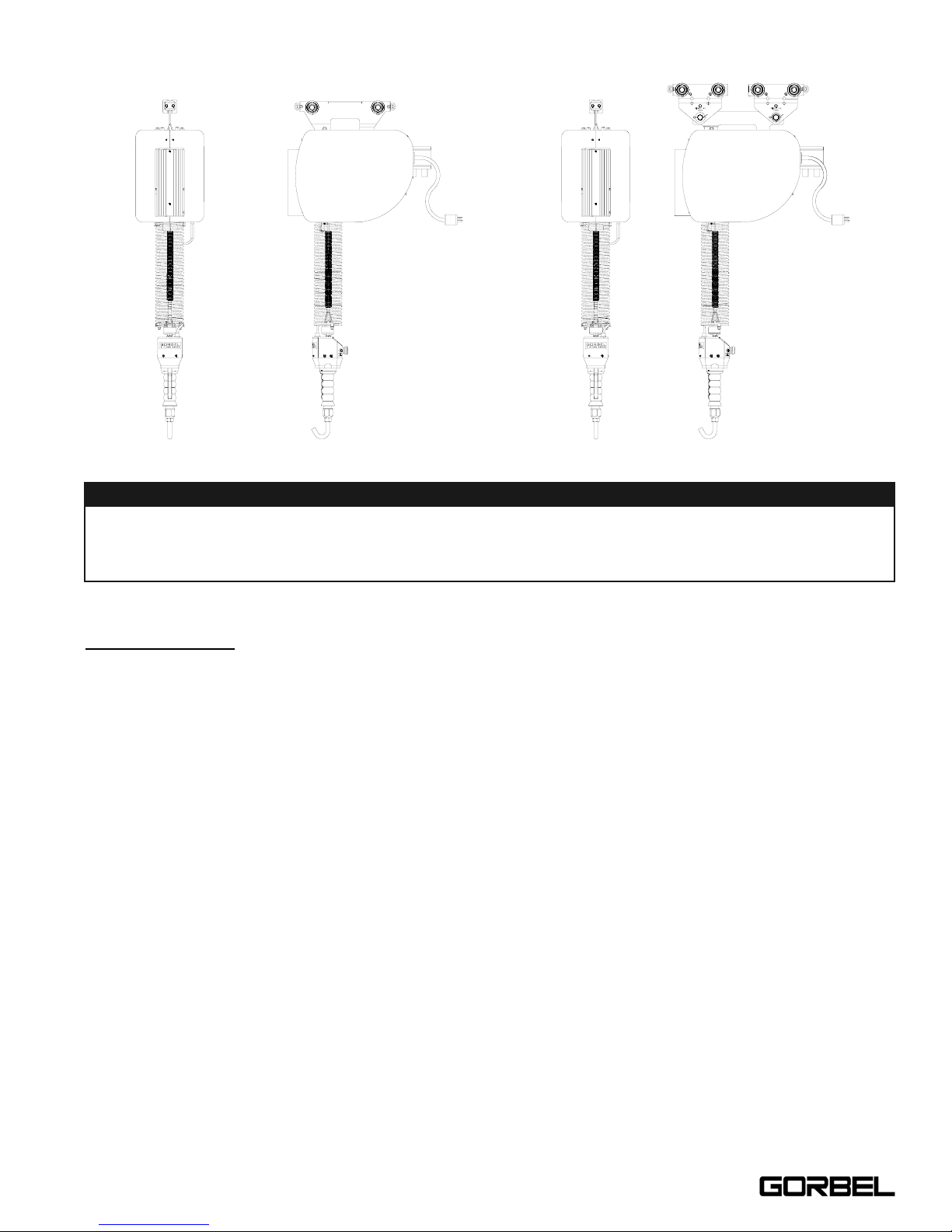
CORRECT G-FORCE® INSTALLATION ORIENTATION
G-FORCE® BX ILD MAIN ASSEMBLY COMPONENT DESCRIPTION
Standard Assembly: The G-Force® BX ILD consists of three (3) main assemblies and they are as follows:
1) Actuator: The Actuator assembly contains the main lifting power transmission of the G-Force® BX
ILD. The drive assembly of the Actuator consists of the ServoMotor with failsafe brake, Gearbox, Main
Drum Pulley, and Controls. The Actuator assembly also contains the Upper and Lower Limit Switches.
See the Lift Functionality and Controls Interface Feature sections for additional details.
2) Coil Cord: The Coil Cord assembly carries the signals from the Handle back to the Controls in the
Actuator assembly. The Coil Cord carries signals back to the Controls for lift speed, lift direction, EStop, and Float Mode (if equipped). Caution must be taken to not over-rotate the Handle, as serious
damage can occur when the Coil Cord binds up around the wire rope.
3) Handle: The Handle is the main interface between the operator and the lifting device. The Handle
comes standard equipped with a lifting hook. The supplied lifting hook can be removed and replaced
with customer tooling. Tooling must meet the guidelines set forth by Gorbel, Inc. Improper tooling
integration will result in degraded performance and may lead to premature failure of the G-Force® BX
ILD. See the Lift Functionality and Controls Interface Feature sections for additional functionality
located at the Handle.
6
WARNING
The BX G-Force® was designed and fully life tested in the installation orientation shown above. Any
modification to the installation orientation of the BX G-Force® without the written consent from Gorbel, Inc.
Engineering will immediately void the warranty. Please contact the factory if a modification to the
installation orientation shown above is desired.
150# BX G-Force®
300/380# BX G-Force®
4/04-Rev. S
®
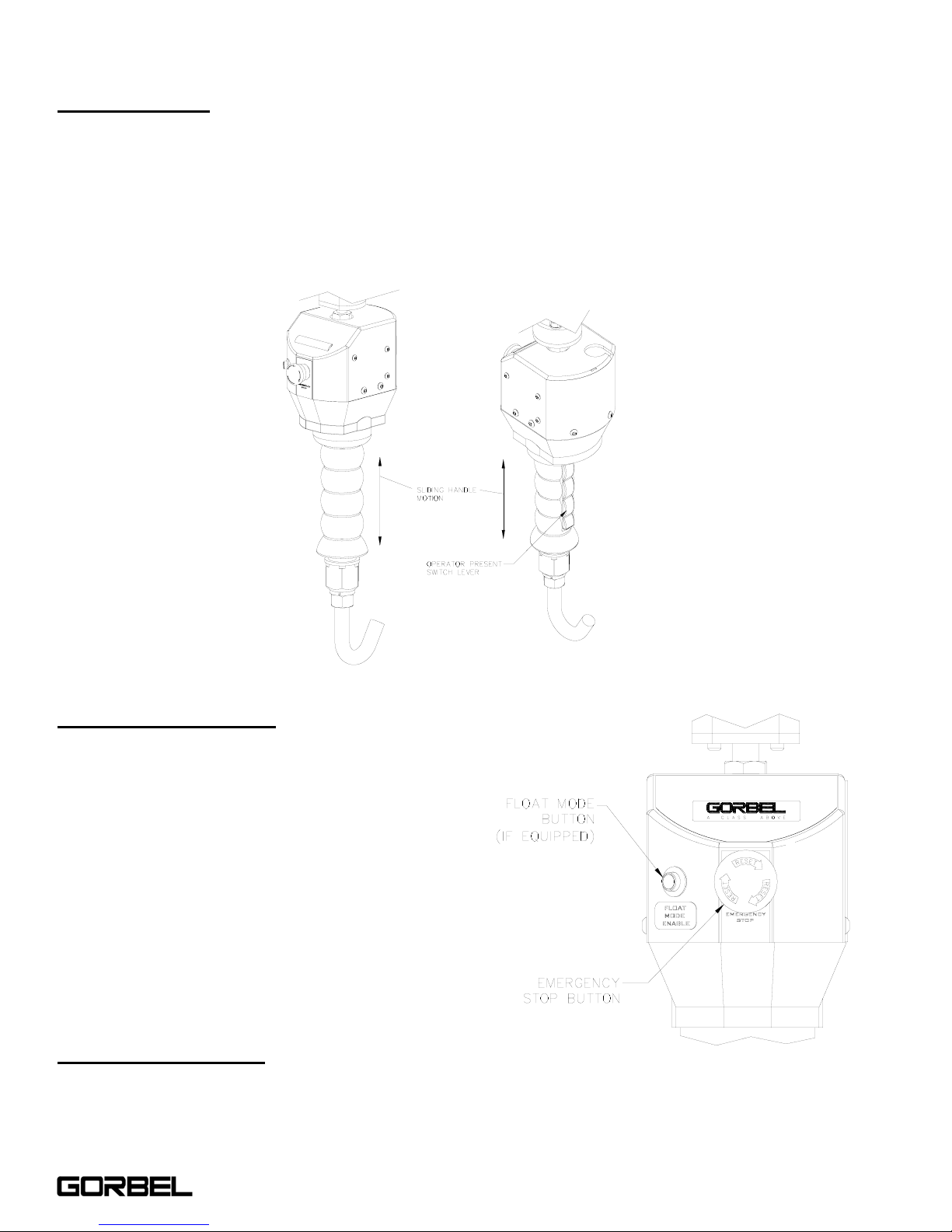
LIFT FUNCTIONALITY
Standard Operation: The Gorbel® G-Force® BX ILD is a servomotor driven, high speed, ergonomic materials
handling device. When the device is in the standard operational mode, the sliding handle of the hand controller
commands the z-axis direction and speed of the lift (reference Diagram A). The handle has a center neutral position
and can slide up and down to provide up and down speed commands to the control system. The further the handle is
displaced from the neutral position, the faster the servo movement to lift or lower the load. The operator lifts or
lowers the load by grasping the handle and moving it up or down as it it were an extension of the operator's arm. The
lift moves slightly slower when a heavy load is lifted, thereby giving the operator some feel for the weight of the load
and thus reducing inertial forces. When depressed, the operator present switch in the handle activates the
servomotor (reference Diagram A). Depressing the operator present switch also releases an electrically operated
mechanical failsafe holding brake in the motor.
Float Mode (System Option): This mode is initiated by
simply pressing the Float Mode Enable button on the hand
controller. In this mode, the operator can simply handle the
load directly with either one or two hands and cause the
load to raise or lower by applying either an upward or
downward force on the load. This mode overrides the need
to depress the operator present switch. The greater the
force applied, the faster the load will move. There is a
standard setting in the controls that safely limits the
maximum speed of travel in Float Mode. Actuating the
operator present switch while in Float Mode will cause the
unit to exit float. While in Float Mode, the load cannot be
increased or decreased because this may cause unwanted
motion. Float Mode must be reinitiated each time the
weight of the live load is changed. The Float Mode enable
button is located on the face of the handle (reference
Diagram B).
Emergency S
top Button: When depressed, the
Emergency Stop (E-Stop) button cuts off all power to the
Controls, and sets the mechanical fail-safe brake. The EStop button is located on the face of the handle (reference
Diagram B). The G-Force® can’t operate until the E-Stop
has been reset.
Diagram A. Sliding Handle - Operator Present Switch Lever.
Diagram B. E-Stop and Float Mode
(optional) Buttons.
7
4/04-Rev. S
®
®

Overload: The servo controller will prevent the lift from moving upward if loaded beyond the maximum capacity of the
G-Force® BX ILD. When an overload condition is sensed, the Overload indicator is illuminated and the lift is
prevented from moving upward. The lift may be moved down to allow for the safe removal of the load. Releasing and
reactivating the operator present switch resets the overload condition.
Limit Switches:
The G-Force® is equipped with both mechanical Upper and Lower Limit switches, located in the
Actuator assembly. When the Upper Limit switch is triggered, the upward motion of the lift stops quickly at a controlled
deceleration rate. The controlled deceleration rate guarantees the load cannot come off the hook. When the Upper
Limit is triggered, the lift will move down but not up. The lower limit is set so that a minimum of two (2) full wraps of
wire rope remain on the drum pulley at all times. When the Lower Limit switch is triggered, the downward motion of
the lift stops quickly at a controlled deceleration rate. When the Lower Limit is triggered, the lift will only move up and
not down.
Slack Switch:
The G-Force® is equipped with a pair of Slack Switches that sense tension in the wire rope and trips
when the wire rope develops slack. The switches are located inside the Actuator assembly. When the Slack Switches
sense slack in the wire rope, downward movement of the lift is stopped to minimize the amount of wire rope unwound
from the drum pulley. When slack in the wire rope is sensed, the lift will only move up but not down.
Remote Mount Handle (System Option):
The lifting device is capable of operating with the handle displaced from
the wire rope (not in-line with the wire rope). For example, if an end user has tooling that is too large for the operator
to safely reach and operate the handle in the standard position, remote mounting the handle is recommended. The
tooling must be mounted (and balanced) on the end of the wire rope, while the handle can be remote mounted. The
tooling must
be attached to the end of the wire rope with a swivel assembly (supplied by Gorbel, Inc.). Failure to mount
the tooling with a swivel assembly can result in premature failure of both the wire rope and the coil cord. The remote
mounted handle is linked to the coil cord via extension cables and connectors. The handle operates exactly the same
as if it were mounted in-line. If the device is equipped for Float Mode, a load cell assembly is provided that must also
be mounted between the tooling and the end of the wire rope. The handle is linked to the load cell via an extension
cable and connectors. **The end user must supply Gorbel, Inc., with the required length of the extension cables such
that they can be safely routed and clamped to the tooling. Always include the distance for bends and turns when
providing the extension length.
CONTROLS INTERFACE FEATURES
1. Jog Switch Push Buttons: The Jog Switch Buttons allow qualified personnel to replace the wire rope (load
cable) on the system. To effectively operate the Jog Switch Buttons, all electrical cables must be connected and
power on. Depressing the “Up” jog switch button will enable the motor and cause the system to reel the wire
rope into the actuator and onto the main pulley. Depressing the “Down” jog switch button will enable the motor
and cause the system to pay out the wire rope from the actuator and off of the main pulley. The handle and
operator present switch are not to be operated during use of the Jog Switch Buttons.
Diagram C. Controls Interface Display.
WARNING
The Jog Switch buttons are for system maintenance and load testing use only, and should not be
manipulated during normal operation of the G-Force® BX ILD. Operation of the Jog Switch buttons during normal operation increases the risk of personal injury to the operator.
8
4/04-Rev. S
®

2. Speed Control Adjustment: The 10 position Speed Control adjustment switch allows the operator to adjust the
speed of the lifting device with a small flathead screwdriver.
3. Power Up Diagnostic Mode:
When the “E-stop” button is released and power is applied to the lift, the servo
motor controller goes into a power up diagnostic mode test. The following are the sections of the diagnostic
mode test:
a) LED Indicator Test: The purpose of this test is to verify the five (5) indicator LEDs are functional.
When the E-stop button is released, the yellow “Power On” LED comes on immediately indicating the
internal 24 volt power is operational. After the servo controller completes a series of self-tests, it turns
on the four (4) remaining LEDs for two (2) seconds to simply verify functionality.
b) Switch Test: After completion of the indicator test, a system switch test is started. The purpose of this
test is to display the state of the “Slack” switches and “Upper and Lower Limit” switches. During the
switch test, the Green “Standard Mode” LED will remain on if the “Upper Limit” switch is triggered (up
limit state) and the Blue “Float Mode” LED will remain on if the “Slack” switches are triggered (wire rope
slack). Once the operator present switch or jog switch is activated, the servo motor controller exits the
power up diagnostic mode and goes into normal operation.
Note: The Yellow Power On indicator will remain on during the power up diagnostic mode test.
4. Power On LED (Y
ellow): The “Power On” LED illuminates when the required 220 VAC, single-phase power
has been correctly applied to the system and the E-Stop button has been released.
5. S
tandard Mode LED (Green): The “Standard Mode” LED illuminates when all system initialization is complete
and the operator present switch is depressed, thus activating the standard mode of operation.
6. Capacity Overload LED (Orange):
The “Capacity Overload” LED illuminates when a load or impact load
greater than the capacity of the hoist has been detected by the system. When this LED illuminates, the
controller will allow the operator to lower the load, but it will inhibit the operator from raising the load prior to
“resetting” the system. To clear the overload fault and “reset” the system, release the switch for approximately 1
to 2 seconds. Once the LED turns off, the system can again be operated.
7. Float Mode LED (Blue):
If the unit is equipped with Float Mode (system option), the “Float Mode” enabled LED
will illuminate when the Float Mode button is pressed on the hand controller and Float Mode has been initiated.
8. System Fault LED (Red):
The “System Fault” LED flashes when basic faults have been detected by the control
system. If a fault has occurred, the “Standard Mode” or “Float Mode” (if equipped) LEDs will turn off.
9
4/04-Rev. S
®

TECHNICAL SPECIFICATIONS
BX Series 150 lbs. 300 lbs. 380 lbs.
Maximum Capacity (Load & Tool) 150 lbs. 300 lbs. 380 lbs.
Max Lifting Speed
Unloaded (feet per minute)
240 fpm 120 fpm 86 fpm
Max Lifting Speed
Fully Loaded (feet per minute)
200 fpm 100 fpm 71 fpm
Max Float Mode (Option) Lifting
Speed (feet per minute)
117 fpm 88 fpm 63 fpm
Max Lift Stroke 7 ft 7 ft 7 ft
Primary Lift Voltage
220 VAC (1 Phase)
+/- 10%
220 VAC (1 Phase)
+/- 10%
220 VAC (1 Phase)
+/- 10%
Amps 5 5 5
Capacity Overload Safety Yes Yes Yes
LED Indicator Lights Yes Yes Yes
Anti-Recoil Yes Yes Yes
Failsafe Brake Yes Yes Yes
Float Mode Capable Yes (Option) Yes (Option) Yes (Option)
Inertia Management Yes Yes Yes
Precision Lift Capability Yes Yes Yes
Drive/Control System Servo Servo Servo
Speed Adjustment Yes Yes Yes
Jogging Capability Yes Ye s Yes
Media Wire Rope Wire Rope Wire Rope
Duty Cycle H5 H5 H5
10
4/04-Rev. S
®
INSTALLATION
STEP 1 - UNPACKING THE G-FORCE® BX ILD
1.1 Carefully remove all items from the box.
1.2 Verify that all components listed on the packing slip are included.
1.3 If any items are missing or were damaged during shipping, please contact Gorbel® Customer Service
immediately.
TIP: Packing list can be found in plastic pocket attached to shipping box.
Diagram 1A. 150# BX series shipped components.
Diagram 1B. 300/380# BX series shipped components.
11
4/04-Rev. S
®

STEP 2 - PRE-ASSEMBLY
2.1 Read entire installation manual before beginning installation of the G-Force® BX ILD.
2.2 Tools and materials typically needed to install/assemble a G-Force® BX ILD are as follows:
• Hand tools
• Plastic cable tie straps
• Ladders/man lifts
2.3 Prior to installing the G-Force® BX ILD, it is a good idea to familiarize yourself with the main components.
- Reference the following layout drawings:
• Figure I1, page 65 - 150# BX Standard Inline Component Layout
• Figure I2, page 66 - 300/380# BX Standard Inline Component Layout
• Figure I3, page 67 - Standard Remote Mount Component Layout
• Figure I4, page 68 - Float Mode Remote Mount Component Layout
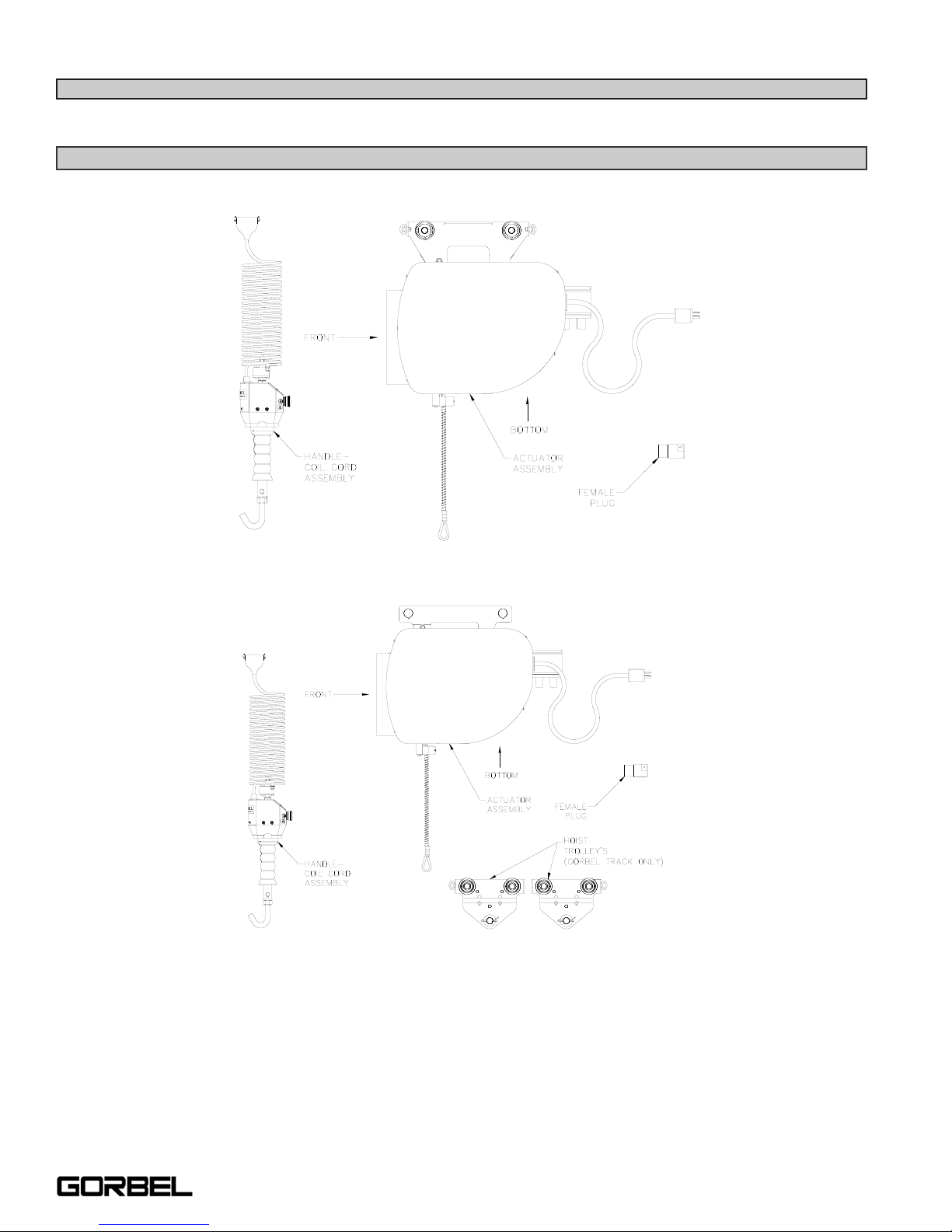
STEP 3 - HANDLE-COIL CORD INSTALLATION (STANDARD INLINE)
3.1 Remove the Cotter and Clevis Pin from the Handle swivel
assembly.
3.2 Feed the wire rope from the Actuator assembly through
the center of the Coil Cord. Slide the looped end of the
wire rope assembly into the yoke of the Handle swivel
assembly (reference Diagram 3A).
3.3 Re-insert the Clevis and Cotter Pin capturing the wire
rope assembly in the Handle swivel assembly (reference
Diagram 3A).
3.4 Remove the Coil Cord mounting clamps from the bottom
side of the Actuator assembly (reference Diagram 3B,
page 13).
3.5 Assemble the Coil Cord to the clamps by capturing the
cord in the opening in the clamp (reference Diagram 3B,
page 13).
3.6 Re-assemble the Coil Cord mounting clamps to the
bottom side of the Actuator assembly (reference
Diagram 3B, page 13).
3.7 Adjust the Coil Cord in the clamps so that the Coil Cord
Connector is conveniently located on the proper side of
the Actuator assembly (reference Diagram 3B, page 13).
3.8 Connect the Coil Cord Connector to the plug on the Control’s Interface located on the bottom side of the
Actuator assembly (reference Diagram 3B, page 13).
3.9 Assure that the coils of the Coil Cord are centered around the wire rope when properly installed. When the
proper alignment of the Coil Cord has been achieved, finish clamping the hardware to fix the Coil Cord in place
(reference Diagram 3B, page 13).
Continue to Step 4 on Page 15.
TIP: This step is best completed on a workbench, prior to installation of the Actuator into the
bridge system.
Diagram 3A. Handle to Wire Rope assembly.
12
Note: For Standard Remote Mounted Handle-Coil Cord Installation, go to Step 3A, page 13.
For Float Mode Remote Mounted Handle-Coil Cord Installation, go to Step 3B, page 14.
4/04-Rev. S
®
STEP 3A - HANDLE-COIL CORD INSTALLATION (STANDARD REMOTE MOUNTED)
3A.1 Attach the wire rope Swivel assembly directly to the end tooling (reference Figure I3, page 67).
3A.2 Remove the Cotter and Clevis Pin from the Swivel assembly.
3A.3 Feed the wire rope from the Actuator assembly through the center of the Remote Mount Coil Cord. Slide
the looped end of the wire rope assembly into the yoke of the Swivel assembly (reference Diagram 3A,
page 12). The Handle in Diagram 3A, page 12, will be replaced by the customer end tooling.
3A.4 Re-insert the Clevis and Cotter Pin capturing the wire rope assembly in the Swivel assembly (reference
Diagram 3A, page 12). The Handle in Diagram 3A, page 12, will be replaced by the customer end tooling.
3A.5 Remove the Coil Cord mounting clamps from the bottom side of the Actuator assembly (reference Diagram
3B).
3A.6 Assemble the Remote Mount Coil Cord to the clamps by capturing the cord in the opening in the clamp
(reference Diagram 3B).
3A.7 Re-assemble the Remote Mount Coil Cord to the clamps to the bottom side of the Actuator assembly
(reference Diagram 3B).
3A.8 Adjust the Remote Mount Coil Cord in the clamps so that the Coil Cord Connector is conveniently located on
the proper side of the Actuator assembly (reference Diagram 3B).
3A.9 Connect the Coil Cord Connector to the plug on the Control’s Interface located on the bottom side of the
Actuator assembly (reference Diagram 3B).
Diagram 3B. Coil Cord to Actuator assembly.
TIP: This step is best completed on a workbench, prior to installation of the Actuator into the
bridge system.
13
4/04-Rev. S
®

3A.10 Assure that the coils of the Remote Mount Coil Cord are centered around the wire rope when properly
installed. When the proper alignment of the Remote Mount Coil Cord has been achieved, finish clamping
the hardware to fix the Remote Mount Coil Cord in place (reference Diagram 3B, page 13).
3A.11 Attach the Standard Remote Mount Handle to the Tooling, being sure to mount at both the top and bottom of
the Remote Mount Handle assembly (reference Figure I3, page 67). Assure that the mounting
arrangement does not effect the operating function of the Handle.
3A.12 Connect the Remote Mount Coil Cord Extension cable from the Remote Mount Handle to the Remote Mount
Coil Cord. Securely clamp the Remote Mount Coil Cord Extension cable to the tooling as needed
(reference Figure I3, page 67).
Continue to Step 4 on page 15.
STEP 3B - HANDLE-COIL CORD INSTALLATION (FLOAT MODE REMOTE MOUNTED)
3B.1 Attach the Load Cell - Swivel assembly directly to the end tooling (reference Figure I4, page 68).
3B.2 Remove the Cotter and Clevis Pin from the Swivel assembly.
3B.3 Feed the wire rope from the Actuator assembly through the center of the Remote Mount Coil Cord. Slide
the looped end of the wire rope assembly into the yoke of the Swivel assembly (reference Diagram 3A,
page 12). The Handle in Diagram 3A, page 12, will be replaced by the customer end tooling.
3B.4 Re-insert the Clevis and Cotter Pin capturing the wire rope assembly in the Swivel assembly (reference
Diagram 3A, page 12). The Handle in Diagram 3A, page 12, will be replaced by the customer end tooling.
3B.5 Remove the Coil Cord mounting clamps from the bottom side of the Actuator assembly (reference Diagram
3B, page 13).
3B.6 Assemble the Remote Mount Coil Cord to the clamps by capturing the cord in the opening in the clamp
(reference Diagram 3B, page 13).
3B.7 Re-assemble the Remote Mount Coil Cord mounting clamps to the bottom side of the Actuator assembly
(reference Diagram 3B, page 13).
3B.8 Adjust the Remote Mount Coil Cord in the clamps so that the Coil Cord Connector is conveniently located on
the proper side of the Actuator assembly (reference Diagram 3B, page 13).
3B.9 Connect the Coil Cord Connector to the plug on the Control’s Interface located on the bottom side of the
Actuator assembly (reference Diagram 3B, page 13).
3B.10 Assure that the coils of the Remote Mount Coil Cord are centered around the wire rope when properly
installed. When the proper alignment of the Remote Mount Coil Cord has been achieved, finish clamping
the hardware to fix the Remote Mount Coil Cord in place (reference Diagram 3B, page 13).
3B.11 Attach the Standard Remote Mount Handle to the Tooling, being sure to mount at both the top and bottom of
the Remote Mount Handle assembly (reference Figure I4, page 68). Assure that the mounting
arrangement does not affect the operating function of the Handle.
WARNING
Remote Mount G-Force® BX Handles must be mounted at both the top and bottom of the Handle
assembly. Failure to mount the Remote Mounted Handle at top and bottom can result in undesirable
performance and/or premature component failure.
TIP: This step is best completed on a workbench, prior to installation of the Actuator into the
bridge system.
14
4/04-Rev. S
®

3B.12 Connect the Remote Mount Coil Cord Extension cable from the Remote Mount Handle to the Remote Mount
Coil Cord. Connect the Float Mode Extension cable from the Remote Mount Handle to the Remote
Mounted Load Cell assembly. Securely clamp the Remote Mount Coil Cord Extension and Float Mode
Extension cable to the tooling as needed (reference Figure I4, page 68).
STEP 4 - INSTALLING THE ACTUATOR ASSEMBLY
4.1 Verify that the G-Force® BX ILD trolley wheels are
correct for the style and capacity track that the unit is
being installed on. Note: Standard 150# G-Force®
BX ILDs come with the wheels pre-assembled to the
Actuator Trolley. Standard 300 and 380# G-Force®
BX ILDs are supplied with an assembled Actuator
Adapter Trolley and two (2) properly sized Hoist
Trolleys when being installed in a Gorbel® Bridge
system. The customer must provide two (2) Hoist
Trolleys when the unit will run in a non-Gorbel®
Bridge system. 150# G-Force® BX ILDs can also be
supplied with an Actuator Adapter Trolley, similar to
that of the 300 and 380# units.
4.2 300 and 380# G-Force® BX ILD: Assemble the
Hoist Trolleys to the Actuator Adapter Trolley.
Remove the Clevis Pin and flat washers from the
Hoist Trolleys. Slide the Trolley legs over the
Adapter Trolley and align the holes. Re-assemble
the Clevis Pin and washers to the Hoist Trolleys
(reference Diagram 4A).
4.3 Remove the end stop from the Bridge and install the G-Force® Actuator into the track. Immediately
re-install the end stops. Roll the Actuator assembly along the full length of the Bridge to assure that the
travel is smooth throughout.
STEP 5 - ELECTRICAL POWER CONNECTION
STANDARD:
5.1 Prior to final wiring, inspect the entire system to assure that all connections are seated properly and are
without kinks or bends. Verify the following connections:
a) Coil Cord to Handle
b) Coil Cord to Actuator Assembly
5.2 Connect a 220 VAC single-phase power source through a Disconnect Switch (by others) to the festooned
power cabling (not provided with G-Force® BX ILD).
5.3 Wire the Female Turnlock Power Plug (provided) to the end of the festooned power cable.
WARNING
Remote Mount G-Force® BX Handles must be mounted at both the top and bottom of the Handle
assembly. Failure to mount the Remote Mounted Handle at top and bottom can result in undesirable
performance and/or premature component failure.
Diagram 4A. 300/380# BX Actuator-Hoist Trolley
Assembly.
15
4/04-Rev. S
TIP: Do not connect to main power until all assembly is complete.
WARNING
Source power to the BX G-Force® unit is to measure 220 VAC (1 Phase) +/- 10%. Minimum Voltage =
198 VAC. Maximum Voltage Must NOT Exceed 242 VAC. Voltages greater than 242 VAC will result in
premature Control System failure.
WARNING
To operate servo drives, it is necessary that certain parts are carrying voltages over 42 VDC. A lifethreatening electrical shock could occur if you touch these parts. This could result in death, severe injury
or material damage. After switching off the servo drive, wait until the DC bus discharge time of at least 5
minutes has passed. The Run LED going out does not indicate that voltage is not present on the device.
®

5.4 After verifying the Disconnect Switch is turned OFF, connect the newly installed receptacle to the Male Plug at
the G-Force® BX ILD.
STEP 6 - AIR CONNECTION (OPTION)
6.1 Assemble one of the Female fittings (provided) to the end of the input air hose (not provided).
6.2 Assemble the other Female fitting (provided) to the end of the tooling airline (not provided).
6.3 Connect both fittings to the respective ends of the Nycoil air hose in the Coil Cord.
6.4 Release the valve supplying air to the G-Force® BX ILD. Inspect and assure that all connections are properly
made and there are no air leaks.
STEP 7 - INITIAL POWER-UP
7.1 Turn on the Disconnect Switch (by others) to apply power to the G-Force® BX ILD.
7.2 Disengage the Emergency Stop (E-stop) button located on the front face of the handle.
7.3 The system will complete the “Power Up Diagnostic Test” described in the “Controls Interface Features” section
of this manual on pages 6 & 7.
7.4 When the “Power Up Diagnostic Test” has been successfully completed, the unit is ready for operation.
7.5 S
tandard Operation: Depress the operator present switch on the Handle and run the unit up and down several
times (at least 20 times in each direction) to assure that there is no mechanical binding in the lift system or
electrical connection issues.
7.6 Float Mode (if equipped):
Lift up a load greater than 20 lbs. Settle the Load and depress the “Float Mode
Enabled” button. ***Do not hold onto the part while initiating Float Mode.*** This will give the unit a false
reading and cause excessive drift. Grasping the load, run the unit up and down several times (at least 20 times
in each direction) to assure proper operation. Float Mode should provide a nice smooth feel.
7.7 Finally, test the operation of any special tooling that may have been integrated to the G-Force® BX ILD.
STEP 8 - ADJUSTING LIFT SPEED
8.1 Take note of the speed of the unit as it is raised and lowered during Step 7. The speed of the G-Force® BX ILD
can be adjusted using the 10 position Speed Selector switch located at the Controls Interface back at the bottom
face of the Actuator assembly.
TIP: G-Force® BX ILD units (Standard Inline or Remote Mounted) that are ordered with Air
power, have a 3/8” ID Nycoil air hose integrated into the full length of the Coil Cord. The Coil
Cord is provided with two (2) Male fittings located at both ends of the air hose. Gorbel also
provides both mating Female fittings for 3/8” ID air hose.
TIP: Do not depress the operator present switch on the Handle during start-up. Depressing
the Handle during the start-up process will result in a drive fault.
TIP: The operator should always keep the operator present switch depressed while
operating the unit in Standard Mode. Frequent pressing and releasing of the operator
present switch (which is common for first time users) will result in jerky movement, and is not
recommended.
WARNING
Gorbel, Inc., does not provide integrated tooling for the G-Force® BX ILD. All tooling related questions should
be directed to the tooling manufacturer or supplier.
16
4/04-Rev. S
®
8.2 Using a small flat-head screwdriver, the position of the switch can be turned to any of the positions that are
numbered from 0 to 9. If a slower speed is desired, position the switch to a smaller number (towards 0). If a
faster speed is desired, position the switch to a larger number (towards 9).
STEP 9 - FLOAT MODE (OPTION)
9.1 Lift and steady the load.
9.2 Without applying any external forces to the load, press the Float Mode Button for one (1) second. When done
correctly, the “Blue” LED light will turn on (the “Yellow” LED will remain on as well).
9.3 The direction and speed of travel is now being controlled by the amount of force that the operator exerts directly
onto the load. To move the load down, put vertical pressure on the load in down direction. To move the load up,
lift up on the load in the vertical up direction. The higher the force exerted on the load, the faster the unit
moves.
STEP 10 - FINAL STEPS
10.1 Please contact the Gorbel® factory (585-924-6262) of any of the following occur. DO NOT ATTEMPT TO
REPAIR UNIT YOURSELF.
• Excessive noise
• Unexpected operation
• Change in performance
• Damage or excessive wear to unit components
• Questions about the unit arise
Please do not be limited by these items only.
10.2 Keep Packing List, Installation Manual, Drawings, and any other inserts filed together in a safe place.
DRIVE FAULT TROUBLESHOOTING CHART
The G-Force® ILD has extensive diagnostic capability. The “Red” System Fault LED flashes when basic faults have
been detected by the control system. If a fault has occurred, the Standard Mode Operating or Float Mode LEDs will
go off.
The red System Fault LED flashes a simple code when a fault has occurred. The sequence of flashes indicates the
type of fault. The sequence consists of a number of short flashes followed by a long pause. The number of short
flashes is the key to determining the fault code. For example, three (3) short flashes followed by a long pause
indicates fault code #3. The sequence continually repeats until the fault is reset. The Fault Codes are listed in the
chart on the next page.
WARNING
If external forces are applied to the load while Float Mode is being initiated, the G-Force® will calculate
a baseline weight that is higher or lower than the actual weight being lifted. When the external force is
removed, the load will begin to drift in the opposite direction of the load that was applied.
WARNING
NEVER remove the load from the G-Force® while still in Float Mode. The drive will interpret the removal
of the load as operator intent to lift the load. Therefore, the Handle will begin to drift up. The speed of
the Handle drift directly correlates to the weight that was removed from the unit. The heavier the
weight, the faster the Handle will travel.
TIP: Gorbel® Customer Service is available from 7am to 7pm Eastern Time Monday -
Thursday and 7am to 5pm Eastern Time Friday.
17
4/04-Rev. S
®

Note: If any of the above listed problems persist, contact Gorbel® Customer Service.
Fault
Code
Failure Possible
Causes
2 DC Bus Under Voltage 1. Low AC line in.
2. Transformer feeding AC in on the MLD is
undersized for the load.
3 DC Bus Over Voltage 1. High AC line in.
2. Regen circuit is not operating correctly.
3. Regen resistor not connected correctly or has
failed.
4 IGBT Fault 1. Too much weight being lifted by the unit (applies if
weight limit set greater than 185 pounds on a 150
pound unit).
2. Loss of an internal power supply voltage.
3. PWM logic error.
4. Over current detected through IGBT.
5 IGBT Over Temperature 1. IGBT is greater than 85 degrees C.
6 Over Current 1. Over current detected through the current sensor.
2. Too much weight being lifted by the unit (applies if
weight limit set greater than 185 pounds on a 150
pound unit).
3. Wire Rope is bound.
4. The motor is wired incorrectly.
5. IGBT failure (applies if code will not reset with the
cycling of power).
7 Motor Over Temperature 1. Motor has exceeded its upper temperature limit.
8 Safety Relay Failure 1. Relay timing closing the motor brake and opening
the motor windings does not meet specified timing
requirements.
9 Unknown Source Reset 1. CPU was reset, but not by power down or via the
JTAG programming port.
10 Missing Clock Caused Reset 1. 16 Mhz clock stopped.
11 Watchdog Timer Caused Reset 1. The CPU has stopped running code feeding
watchdog timer.
12 XTAL Oscillator Startup Error 1. The external 16 Mhz oscillator did not start.
13 Unexpected Hardware Configuration 1. Mode switch does not match jumper or software
configuration.
2. Handle pulled in during power up.
3. Power interruption during operation.
18
4/04-Rev. S
®

WIRE ROPE INSPECTION
1) Frequent Inspection
The operator or other designated person should visually inspect all ropes at the start of each shift. These visual
observations should be concerned with discovering gross damage, such as listed below, which may be an
immediate hazard:
(a) distortion of the rope such as kinking, crushing, unstranding, birdcaging, main strand displacement, or
core protrusion;
(b) general corrosion;
(c) broken or cut strands;
(d) number, distribution, and type of visible broken wires. [See next section on rope replacement]
When such damage is discovered, the rope shall either be removed from service or given an inspection as
detailed in the next section.
2) Periodic Inspection
The inspection frequency shall be determined by a qualified person and shall be based on such factors as
expected rope life as determined by experience on the particular installation or similar installations; severity of
environment; percentage of capacity lifts; frequency rates of operation; and exposure to shock loads.
Inspections need not be at equal calendar intervals and should be more frequent as the rope approaches the
end of its useful life.
A designated person shall perform periodic inspections. This inspection shall cover the entire length of rope.
The individual outer wires in the strands of the rope shall be visible to this person during the inspection. Any
deterioration resulting in appreciable loss of original strength, such as described below, shall be noted, and
determination shall be made as to whether further use of the rope would constitute a hazard:
(a) points listed in previous section on frequent inspection;
(b) reduction of rope diameter below nominal diameter due to loss of core support, internal or external
corrosion, or wear of outside wires;
(c) severely corroded or broken wires at end connections;
(d) severely corroded, cracked, bent, worn, or improperly applied end connections.
Special care should be taken when inspection sections of rapid deterioration, such as the following:
(a) sections in contact with saddles, equalizer sheaves, or other sheaves where rope travel is limited;
(b) sections of rope at or near terminal ends where corroded or broken wires may protrude;
(c) sections subject to reverse bends;
(d) sections of ropes that are normally hidden during visual inspection, such as parts passing over sheaves.
WIRE ROPE MAINTENANCE
1) Rope should be stored to prevent damage or deterioration.
2) Rope shall be unreeled or uncoiled in a manner to avoid kinking of or inducing a twist in the rope.
3) Before cutting rope, means shall be used to prevent unlaying of the strands.
4) During installation, care should be observed to avoid dragging of the rope in dirt or around objects that will
scrape, nick, crush, or induce sharp bends.
19
4/04-Rev. S
®
5) Rope should be maintained in a well-lubricated condition. Gorbel recommends using Chain and Cable
Penetrating oil for lubrication. Lubricant applied as part of a maintenance program shall be compatible with the
original lubricant. Lubricant applied shall be of the type that does not hinder visual inspection. Immediately after
inspection, lubricant shall be applied before rope is returned to service. Those sections of rope that are located
over sheaves or otherwise hidden during inspection and maintenance procedures require special attention when
lubricating rope. The object of rope lubrication is to reduce internal friction and to prevent corrosion.
WIRE ROPE REPLACEMENT CRITERIA
1) No precise rules can be given for determination of the exact time for rope replacement, since many factors are
involved. Once a rope reaches any one of the specified removal criteria, it may be allowed to operate to the end of
the work shift, based on the judgement of a qualified person. The rope shall be replaced after that work shift, at the
end of the day, or at the latest time prior to the equipment being used by the next work shift.
2) Removal criteria for the rope replacement shall be as follows:
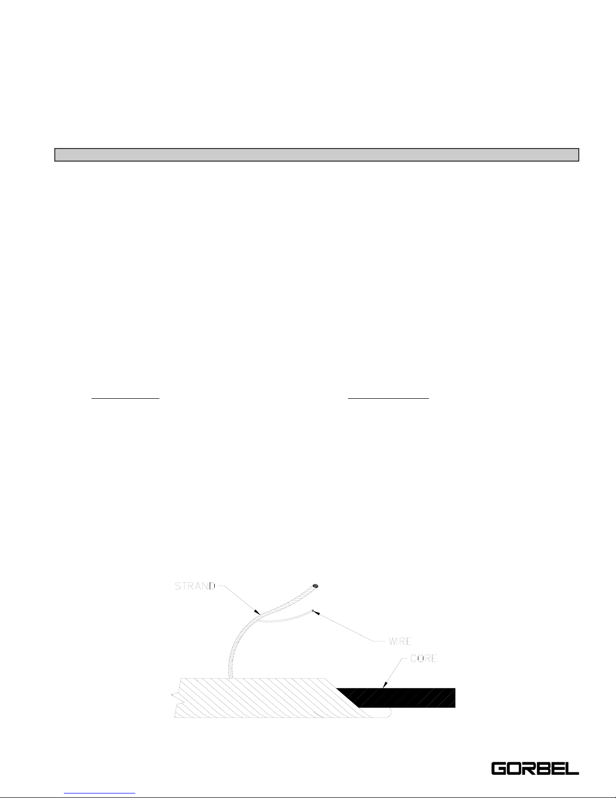
(a) in running ropes, 12 randomly distributed broken wires in one lay or four broken wires in one strand in
one lay (reference Diagram E below);
(b) one outer wire broken at the contact point with the core of the rope, which has worked its way out of the
rope structure and protrudes or loops out from the rope structure;
(c) wear of one-third the original diameter of outside individual wires;
(d) kinking, crushing, birdcaging, or any other damage resulting in distortion of the rope structure;
(e) evidence of heat damage from any cause;
(f) reductions from nominal diameter greater than those shown below:
Maximum Allowable
Reduction From
Rope Diameter
Nominal Diameter
Up to 5/16 in. (8 mm) 1/64 in. (0.4 mm)
3) Broken wire removal criteria applies to wire ropes operating on steel sheaves and drums. However, results of
internal testing have shown that rope replacement follows the same criteria regardless of sheave or drum
material.
4) Attention shall be given to end connections. Upon development of two broken wires adjacent to a socketed end
connection, the rope should be resocketed or replaced. Resocketing shall not be attempted if the resulting rope
length will be insufficient for proper operation.
5) Replacement rope and connections shall have strength rating at least as great as the original rope and
connections furnished by the hoist manufacturer. A rope manufacturer, the hoist manufacturer, or a qualified
person shall specify any deviation from the original size, grade, or construction.
Diagram E. Wire Rope Composition Diagram.
20
4/04-Rev. S
®

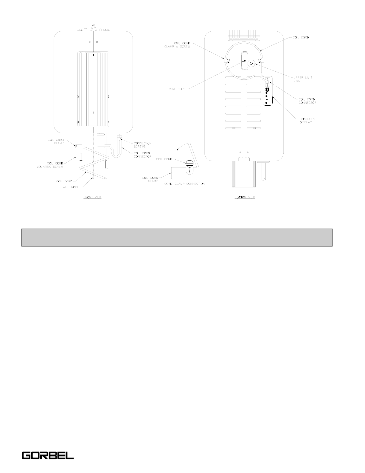
WIRE ROPE REPLACEMENT INSTRUCTIONS
Note: All referenced drawings below are for a 150# unit. The procedure remains the same regardless of capacity.
1) Depress the Emergency Stop (E-Stop) button on the Handle. Disconnect power from the unit.
2) Remove the Covers from the Actuator assembly.
a) First, remove the Controls side Cover (Item #2, Figure A13, page 31) from the Actuator assembly.
To remove this Cover you must first unscrew and remove the Coil Cord Plug from the Controls
Interface. Remove the Coil Cord mounting Clamp (Item #11, Figure A13, page 31). Remove the
three (3) mounting screws (Item #10, Figure A13, page 31) from the Controls side Cover only.
Finally, remove the Cover mounting bolt (Item #7, Figure A13, page 31) at the Actuator Frame.
Slide the Cover off of the Actuator assembly.
b) Remove the remaining side Cover (Item #3, Figure A13, page 31) from the Actuator assembly.
Remove the Coil Cord mounting Clamp (Item #11, Figure A13, page 31). Remove the Upper Limit
Switch Disc (Item #5, Figure A13, page 31). Finally, remove the Cover mounting bolt (Item #7,
Figure A13, page 31) at the Actuator Frame. Slide the Cover off of the Actuator.
3) Remove three (3) of the Heatsink mounting bolts (Item #8, Figure A9, page 29), leaving the lower left bolt in
place. Loosen, but do not remove, the lower left mounting bolt and rotate the Heatsink down towards the floor.
This will support the Heatsink while wire rope replacement is being performed.
4) Remove the Nylon Drum Cover (Item #2, Figure A8, page 28) from the Actuator. Remove the six (6) mounting
bolts and lockwashers (Item #s: 3 & 4, Figure A8, page 28) and slide the Drum Cover off of the Main Drum
Pulley.
5) Re-attach the Coil Cord Plug to the Controls Interface and Power to the unit.
6) Release the Emergency Stop (E-Stop) button on the Handle. At the Controls Interface, jog the unit down until
the remaining Wire Rope has been payed off of the Main Drum Pulley.
7) Depress the Emergency Stop (E-Stop) button on the Handle and disconnect Power to the unit.
8) Detach the Wire Rope from the Handle. Remove the cotter and clevis pins from the Handle Swivel assembly.
Pull the damaged Wire Rope out of the Swivel assembly.
9) Set the Handle down on a secure base while Wire Rope replacement is taking place.
10) Remove the Upper Limit Donut (Item #10, Figure A6, page 27) from the broken wire rope assembly.
11) Remove the Wire Rope termination cover (Item #3, Figure A6, page 27) by removing the mounting bolts (Item
#14, Figure A6, page 27) from the Main Drum Pulley.
12) Remove the terminated end of the Wire Rope from the Main Drum Pulley. Do so by simply lifting the terminated
end out of the groove in the Drum Pulley. Pull the damaged wire rope completely out of the Actuator assembly.
13) Unless otherwise instructed, discard the damaged wire rope.
14) Remove the one (1) Extension Spring (Item #5, Figure A5, page 26) from the Heatsink side of the Actuator
Frame by unscrewing the shoulder mounting bolt (Item #9, Figure A7, page 28) attached to the Idler Guide
Plate (Item #3, Figure A7, page 28).
15) Remove the two (2) Snap Rings (Item #8, Figure A7, page 28) from the Idler Pulley Shafts (Item #4, Figure A7,
page 28) and remove the Idler Pulley Guide Plate (Item #3, Figure A7, page 28).
16) Unscrew the T
OP Idler Pulley Shaft (Item #4, Figure A7, page 28) only, using a 5/16” open-end wrench.
TIP: Wire rope replacement is to be performed by qualified maintenance personnel only.
21
4/04-Rev. S
®
 Loading...