

Page 1

AR5 AUDIO RECEIVER
GoRave Receiver & Amplier
Owner’s Manual
Installation and Operation
TM
Version 1.2 / 12-12-2013
Page 2
GORAVE AR
AUDIO RECEIVER & AMPLIFIER
TM
Owner’s Installation and Operation Manual
V1.2 / 12-12-2013
1. Getting Started
1.1 Thank You
Thank you for the purchase of your GoRave AR5 audio receiver & amplier. The GoRave AR distributes audio
from mobile and wired devices to loudspeakers installed in your space. Use it with GoRave Audio Senders to
cast audio into your space and swap between your devices and content sources.
This manual provides basic installation and operating instructions. The manual will help you experience the
performance your system was designed to produce.
1.2 Safety Precautions
FOR YOUR SAFETY:
► Carefully read this manual before connecting or operating your GoRave AR receiver/amplier. Keep this
manual for later reference.
► Allow for ventilation around your GoRave AR module for heat dissipation. Keep the GoRave AR away
from appliances that produce heat.
► Connect the GoRave AR to the power outlet with the supplied power supply cable. Follow all local elec-
trical codes for power connection.
► Stop using the GoRave AR and have it inspected and/or serviced by qualied service personnel if:
● The power supply cord or plug has been damaged.
● Objects have fallen into or liquid has been spilled into the unit.
● The unit has been dropped or damaged in any way.
1.3 Where to Install
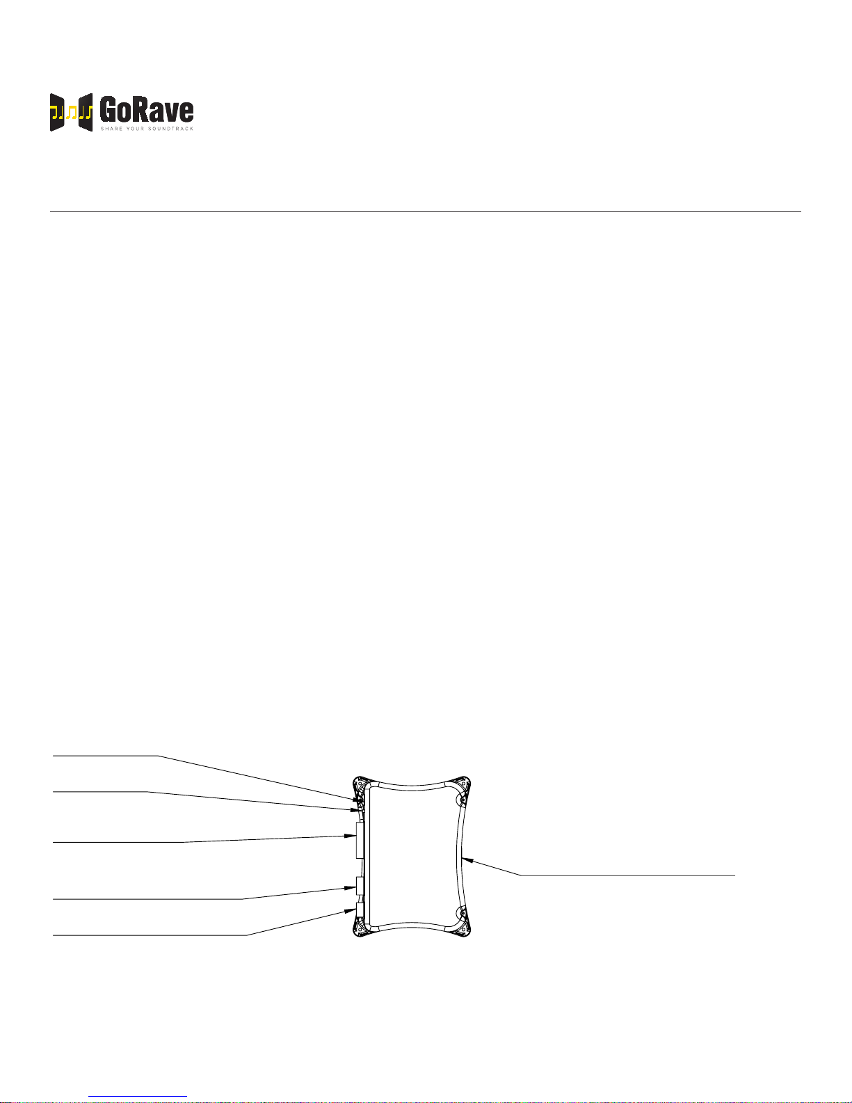
LED indicator
TOP
Pairing button
Main Power: 90 - 270VAC
Speaker outputs
White: Neutral
Black: Line
1 meter molded NEMA-15 power plug
Auxiliary audio input (wired)
Serial port
Fig 1: top view of a GoRave AR receiver/amplier.
Page 3
GORAVE AR
AUDIO RECEIVER & AMPLIFIER
TM
Owner’s Installation and Operation Manual
DINING ROOM
V1.2 / 12-12-2013
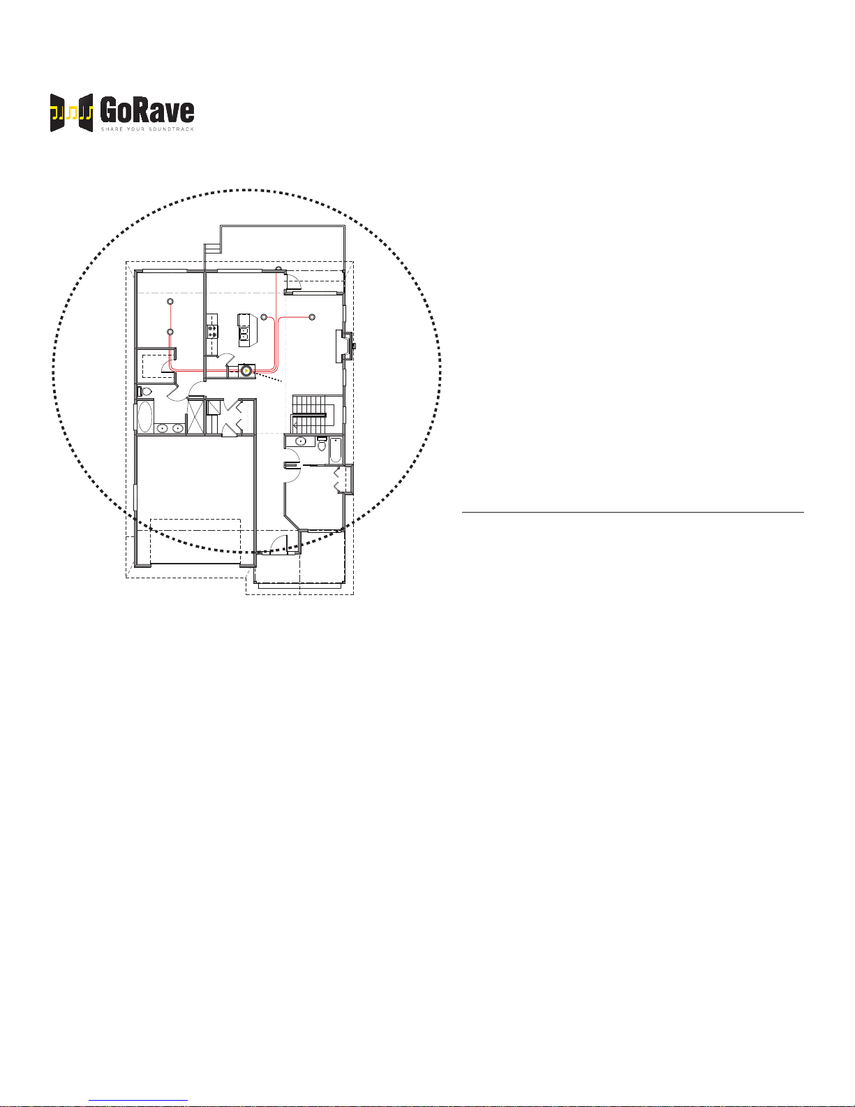
The wireless GoRave Audio Senders offer a transmitting range of 40 feet for the USB style and 30
feet for all other styles. Install your GoRave AR5
receiver amplier inside this transmitting radius.
Include the distance needed to transmit from out-
side spaces when deciding on the best location
for your AR5 receiver amplier.
MASTER BEDROOM
LIVING
ROOM
Centrally installed
GoRave SE
Mount your GoRave AR receiver/amplier with
adequate space around the unit for all audio and
power connections as well as easy access the
receive/pair button and LED status indicator. Use
four screws (and anchors) to secure the unit to
the surface.
GARAGE
BEDROOM
2. Power and Control
2.1 AC Power Connection
The GoRave AR receiver/amplier should be
Fig 2: typical installation in central closet or pantry to maximize useful
35’ transmitter range (range indicated by dashed circle). In this example, the owners have opted for stereo loudspeakers to be installed in
their kitchen, master bedroom and one outdoor speaker for the patio.
electrical codes require a hard wire connection instead of the AC power plug and socket connection, consult a
qualied electrician for installation assistance.
plugged directly into a grounded power receptacle
rated to deliver the power required by the GoRave
AR unit and the components connected to it.
Connect the power cord to the AC outlet. If local
The GoRave AR receiver/amplier will operate with a line voltage of 90-270 VAC with a line frequency of either
50Hz or 60Hz. There is no need to convert or adjust the unit in any way.
NOTE: If you are going to be away from home for an extended period of time such as a month-long vacation, it
is a sensible precaution to unplug your amplier (as well as other audio and video components) while you are
away.
2.2 Power Indicator
The LED indicator beside the send/receive pairing button will pulse when the power cord is plugged in to an AC
outlet, indicating that the amplier is turned on. The GoRave AR5 has a built in low power sleep mode where
the power supply and ampliers will turn off when audio is not playing.
Page 4

GORAVE AR
AUDIO RECEIVER & AMPLIFIER
TM
Owner’s Installation and Operation Manual
V1.2 / 12-12-2013
2.3 Protection Circuitry
The GoRave AR features a thermal protection circuit that protects the amplier against potential damage in
the event of extreme or faulty operating conditions. The GoRave AR’s protection circuit is independent of the
audio signal and has no impact on sonic performance. The protection circuit monitors the temperature of the
output devices and shuts down the amplier if temperatures exceed safe limits. It is unlikely you will ever see
this protection circuitry in action. However, should a faulty condition arise, the amplier will stop playing and the
LED indicator on the AR5 unit will ash quickly. The amplier will automatically resume normal operation when
a fault condition is removed.
In most cases, the protection activates because of a fault condition such as shorted speaker wires or inadequate ventilation leading to an overheating condition. In very rare cases, highly re active or extremely low
impedance speaker loads could cause the protection circuit to engage.
If the protection circuitry triggers repeatedly and you are unable to isolate and correct the faulty condition, contact your GoRave reseller for assistance in troubleshooting.
2.4 CAT6 Control Connection
Along with installing speaker wires, GoRave recommends running a CAT6 cable from your internet / telco /
electrical closet to the GoRave AR installation location. The CAT6 cable will serve for future GoRave internet
remote control, home automation and television options.
3. Inputs and Outputs
The GoRave AR has one wireless and one wired input connection. The wireless connect enables input from
one or more wireless GoRave Audio Senders. The auxiliary wired input enables you to play analog audio from
conventional audio sources such as a CD player.
3.1 Wired Input Connection
Your GoRave AR5 Amplier / Receiver has provision for 1 auxiliary connection from an external audio device.
You can connect your home stereo, cd player, Airport Express, Blackberry Gateway, Xbox etc.
Connect the Auxiliary Audio Input to a GoRave HCRCA2W RCA wall connection plate using 4 conductors of
speaker wire. Use cable as suggested in section 4.2 of this manual. Connect left to the white jack on the wall
plate and right to the red jack.
To connect to your external device use a 3.5mm to RCA cable, supplied or a common stereo RCA cable, not
supplied.
When connected, use the controls on the auxiliary device to control volume and operating functions.
Page 5
speaker
speaker
GORAVE AR
AUDIO RECEIVER & AMPLIFIER
TM
Owner’s Installation and Operation Manual
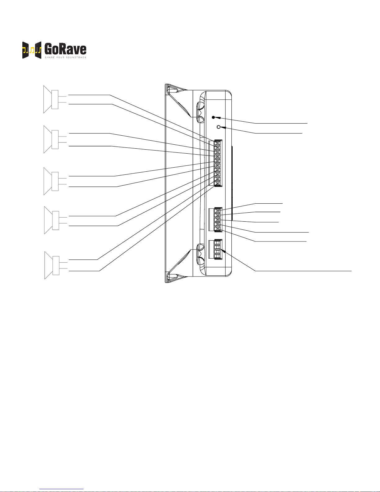
Left Front -
Left Front +
Left Rear -
Left Rear +
V1.2 / 12-12-2013
LED indicator
Push button
speaker
Right Rear Right Rear +
Aux analog audio input
(wired interface):
Right +
Right -
Shield
speaker
Right Front -
Right Front +
Left (Mono) +
Left (Mono) -
Mono -
speaker
Fig 3: front view of a GoRave AR receiver/amplier with speaker outputs (left) and wired inputs (right).
3.2 Connecting and playing with wireless Audio Senders
To cast audio from a GoRave Audio Sender that has been paired to a GoRave AR5 Audio Receiver, simply
insert the Audio Sender into a device, play music, watch video while your enjoy the audio through you GoRave
speakers.
Mono +
Serial programming port
Your GoRave AR5 Audio Receiver is exible and adaptable to enhance the way you live today and in the future. You can choose to have the your AR5 open to receive audio from any GoRave Audio Sender or you can
choose for your GoRave AR5 to receive audio from specic Audio Sender(s) of your choosing. This process is
called pairing.
A GoRave AR5 can be paired with a maximum often (10) GoRave Audio Senders. To establish new pairing
relationships, the pairing memory can be cleared at any time. Your GoRave App will identify the AR5 Audio
Receivers it can play to.
Page 6
GORAVE AR
AUDIO RECEIVER & AMPLIFIER
TM
Owner’s Installation and Operation Manual
V1.2 / 12-12-2013
3.3 How to clear paired Audio Senders from the GoRave AR5
Push and hold the Pairing Button on the AR5. The LED indicator will ash three times to conrm that you have
cleared the pairing memory. You are now able to establish new pairing relationships or leave the AR5 open to
receive audio from ALL Audio Senders.
3.4 How to pair an Audio Sender to a GoRave AR5 Audio Sender
a) Insert the GoRave Audio Sender into your device.
b) Open the GoRaveapp, tap the top of the screen to name the Audio Sender if it is not already named.
c) Play music on the device.
d) Press the pairing button once on the AR5 receiver toinstruct the AR5 to look for a NEW Audio Sender.( In
the pairing process, your AR5 is looking for ALL NEW Audio Senders and you may encounter hearing music that is not from your device. Press the Pairing Button again to instruct the AR5 to look for the next new
Audio Sender. Repeat this until you hear your music from your device.
e) The GoRave app will ask you to name the AR5, tap the screen and type in a suitable name.
f) When you hear the music from your device through the GoRave speakers, press the button once more to
pair. You have 20 seconds to complete this step. The LED will ash 3 times conrming the pairing process
is complete.
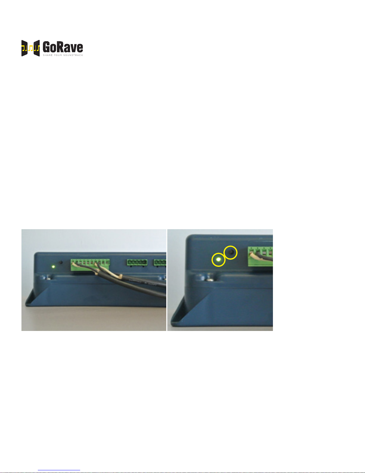
Fig 4: front view of GoRave AR enclosure showing Receive/Send button,
LED indicator (highlighted
by yellow circle on right)
as well as wired speaker
outputs and analog audio
input.
g) The GoRave app will identify each AR5 it can connect with as well enable control the volume on each AR5.
3.5 Connecting the wireless USB Audio Sender on a MacOS computer
a) Insert the USB Audio Sender into the Mac’s USB port.
b) Click the Apple in the top left corner of the screen and choose “System Preferences”.
c) Click on “Sound”.
d) In the Sound settings screen, click the “Output” tab.
e) Select “SKAA Transmitter” from the list of audio output devices. This setting enables the computer to auto-
matically transmit from the USB Audio Sender when it is inserted in the device.
f) Adjust the volume to desired level.
g) Play an audio le on your Mac and follow the pairing process to add this USB Audio Sender to the GoRave
AR’s list of recognized transmitters.
Page 7
GORAVE AR
AUDIO RECEIVER & AMPLIFIER
TM
Owner’s Installation and Operation Manual
V1.2 / 12-12-2013
h) Press and hold the Receive/Pair button on the GoRave AR for 10 seconds to pair the Audio Sender.
i) The LED indicator will turn solid green to show success and the GoRave AR will play the audio from your
Mac computer.
3.6 Connecting the wireless USB Audio Sender on a Windows computer
a) Insert the USB Audio Sender into the Windows device. It will automatically install the required drivers and
enable wireless audio transmission.
b) Adjust the volume on the device to desired level.
c) Press the Receive/Pair button on the GoRave AR for one second to pair the Audio Sender.
d) LED turns solid green in few seconds to show success.
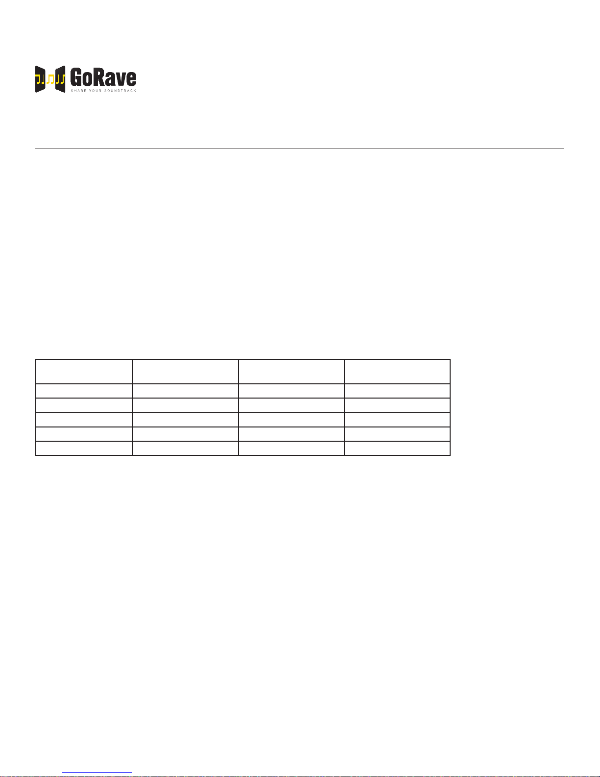
3.7 LED status indicator states
LED Status: AR5 State: LED Pattern:
On Receiving & playing audio
Off No power
Fast Pulse Looking for a new sender
Slow Pulse Looking for a paired sender
3 fast blinks OK, conrmed x3
10 fast blinks Error executing request x10
GoRave AR
wireless
receiver/amplifier
Phone or
other device
transmitting
audio
AC power
connection
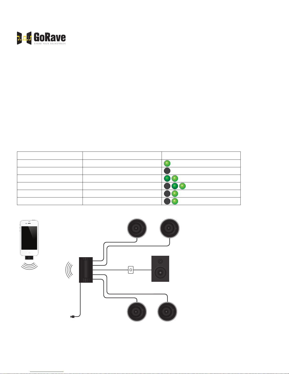
Fig 5: generic wiring diagram showing a mobile computing device transmitting audio to a GoRave AR wireless receiver amplier via a
GoRave Audio Sender. The amplier then distributes the audio to two stereo speaker pairs and one mono weather-resistant outdoor
speaker.
L
R
Mono wall mounted
outdoor loudspeaker
Volume control
for outdoor
L
R
Two stereo pairs of ceiling installed loudspeakers
Page 8
GORAVE AR
AUDIO RECEIVER & AMPLIFIER
TM
Owner’s Installation and Operation Manual
V1.2 / 12-12-2013
4. Loudspeakers
4.1 Speaker Selection
Combine GoRave loudspeakers with your GoRave AR receiver/amplier. GoRave components are tuned to
work together and deliver the best possible audio experience.
If you are installing other loudspeakers, use a speaker with a nominal impedance of 4 ohms or higher. Driving
multiple speakers in parallel or bridged conguration is not recommended.
4.2 Speaker Wire Selection
Use insulated two-conductor stranded wire to connect your GoRave AR5 to your GoRave loudspeakers. The
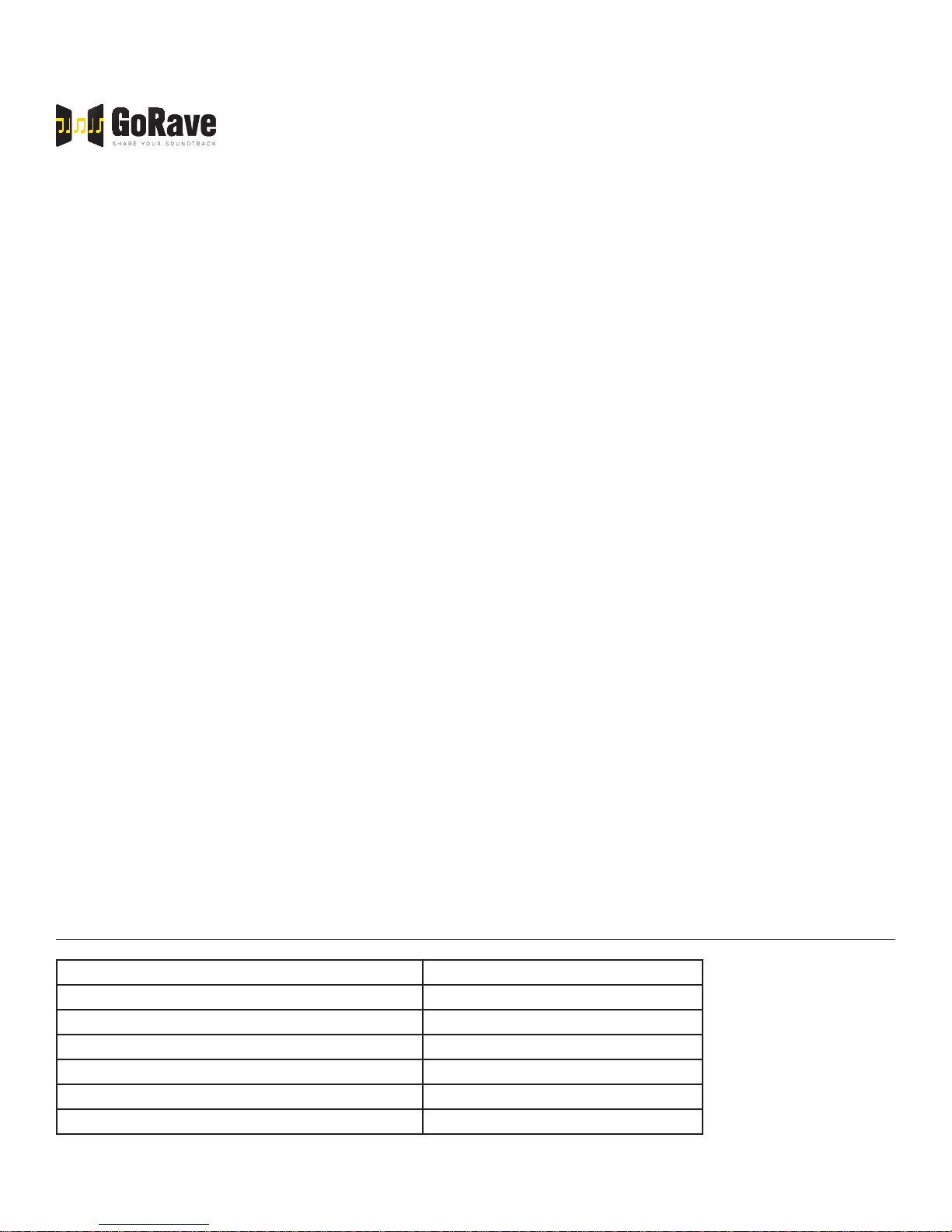
size and quality of the wire can have an audible effect on the performance of the system. Based on resistance
(Ohms) per foot on stranded cable, the table below provides a distance guideline to ensure your cable is sized
to deliver the best audio experience. Ensure the cable you select meets local building codes.
Wire Gauge Distance (8 ohm speaker
impedance)
18 AWG 60' / 18.2m 45' / 13.6m 30' / 9.1m
16 AWG 100' / 30.4m 75' / 22.8m 50' / 15.2m
14 AWG 150' / 45.7m 110' / 33.5m 75' / 22.8m
12 AWG 250' / 76.2m 180' / 54.8m 125' / 38.1m
10 AWG 400' / 122m 300' / 91.4m 200' / 61m
Distance (6 ohm speaker
impedance)
Distance (4 ohm speaker
impedance)
4.3 Connecting the Speakers
Review the “Speaker Outputs” diamgram shown in Figure 3. Connect the wire from the speakers to the 10-pin
terminal block that was included with your GoRave AR. Give yourself enough slack so you can move the components enough during installation and give easy access to the speaker connectors.
When attaching bare wires directly to the binding posts, separate the rst few inches of the wire conductors
and strip about 1/8” (4mm) of insulation from the end of each conductor. Be careful not to cut into the wire
strands. Twist the strands of each conductor together to avoid fraying. Unscrew (turn counterclockwise) the
binding terminal shaft and insert the bundled wire into the hole in the shaft. Turn the screw clockwise to clamp
the connector wire rmly in place.
NOTE: Be sure there are no loose wire strands that could touch adjacent wires or connectors. Short circuits
caused by loose strands touching will trigger the amplier’s protection circuitry.
4.4 Polarity and Phasing
The polarity (the positive/negative orientation of the connections) for every speaker and amplier connection
must be consistent so all the speakers will be in phase. If the polarity of one connection is mistakenly reversed,
bass output will be very weak and stereo imaging degraded.
Page 9

GORAVE AR
AUDIO RECEIVER & AMPLIFIER
TM
Owner’s Installation and Operation Manual
V1.2 / 12-12-2013
Identify the positive and negative conductors and be consistent with every speaker and amplier connection.
All wire is marked so you can identify the two conductors. There may be ribs or a stripe on the insulation of one
conductor, the wire may have clear insulation with different color conductors (copper and silver) or there may
be polarity indications printed on the insulation.
5. Troubleshooting
5.1 General Concepts
Most issues in audio systems are result of incorrect connections or improper control settings. If you encounter
problems, isolate the area of difculty, check the control settings, determine the cause of the fault and make
the necessary changes.
Check the following conditions if you are unable to get sound from your GoRave AR.
5.2 No Power
► Is the GoRave Audio Receiver connected to power?
► Is the LED status indicator on GoRave AR lit solid green?
► No main power to the GoRave AR (LED is off). Check AC power connections at the amplier and the
AC outlet.
5.3 No Sound
If the GoRave AR5 is powered on but not producing sound, check that the LED indicator is pulsing.
► If LED indicator is pulsing slowly:
● The AR5 Audio Receiver is seeking a signal from a paired Audio Sender.
● Use The GoRave App to conrm that the Audio Sender you are using is paired.
● Increase the volume on your device.
● Is your device on mute?
● Is your device further than 30 feet (9.1 meters) away?
● Is another device playing with a pair Audio Sender on low volume or mute?
► If LED indicator is pulsing rapidly:
● The GoRave AR5 Amplier / Receiver is looking for a new Audio Sender.
● Select and insert an Audio Sender into a device and play music.
● When you hear your music, push the pairing button to pair the selected Audio Sender.
► Is the device with the Audio Sender turned on?
► Is audio playing on the device?
Page 10
GORAVE AR
AUDIO RECEIVER & AMPLIFIER
TM
Owner’s Installation and Operation Manual
V1.2 / 12-12-2013
► Is the device on mute?
► Is the volume on the device set too low?
► Do you have more than one Audio Receiver installed in your space?
● Is your audio playing from speakers connected to the other Audio Receiver?
● Does the GoRave app on your device show the Audio Receiver you want to play to?
If not, pair the device.
● The Audio Receiver may be receiving a signal from another Audio Sender at low volume or mute.
Stop audio playback from the other Audio Sender by pressing pause or removing the Audio Sender
from the device.
5.4 Poor Quality Audio Playback
► Crackle or static in the speakers may result from connection problem with Audio Sender. This can hap-
pen if you’re holding your device and pushing/moving the Audio Sender with your ngers.
► Unexpected pauses or drops in playback can result from the Audio Sender being out of range from the
Audio Receiver.
5.5 LED Indicator Is Continuously Flashing (Fast Blink)
The LED indicator will continuously ashing at a fast, high frequency when one of following conditions is detected:
a) The GoRave AR was set to operate beyond its specications. To resolve the issue, try:
• Lowering the volume
• Reseating the wireless Audio Sender
• Turn the power to the GoRave AR off then on.
b) The fault protection circuit has shut off the amplier. This occurs only when there is faulty speaker wiring,
or a problem with overheating. Unplug the system and wait for the amplier to cool. Correct the cause then
reconnect the power. The GoRave AR will reset. If the problem is not corrected or reoccurs, contact your
professional installer.
6. Specications
Continuous Power Output 25 watts per channel
Frequency Response 20 to 20 kHz
Speaker Impedance 4 to 16 ohms
Power Requirements 90-270 VAC 50/60Hz
Power Consumption Maximum 160 watts
Dimensions (WxHxD) 166 x 76 x 226 mm
Weight (net) 1.5 kg
Page 11

GORAVE AR
AUDIO RECEIVER & AMPLIFIER
TM
Owner’s Installation and Operation Manual
V1.2 / 12-12-2013
All specications are accurate at the time of printing. GoRave reserves the right to make improvements without
notice.
7. Warranty
1-YEAR LIMITED WARRANTY
GoRave Electronics Ltd. (“GoRave”) warrants that the GoRave AR receiver/amplier (GoRave AR) you have
purchased shall be free of any defects in parts and workmanship if used under normal operating conditions for
a period of one (1) year from the date of purchase, except this warranty shall apply only to the original purchaser. PLEASE RETAIN YOUR SALES RECEIPT, AS IT IS YOUR PROOF OF PURCHASE COVERING YOUR
LIMITED WARRANTY. THIS WARRANTY IS VOID WITHOUT SUCH PROOF OF PURCHASE.
Defective units will be repaired or replaced without charge, at GoRave’s discretion, with a like or comparable
product by the Dealer if presented with proof of purchase to the Authorized GoRave Dealer from whom the
GoRave AR was purchased. Any repair or service performed by any person or entity other than GoRave is not
covered by this limited warranty. Transportation costs are not included in this warranty.
This limited warranty becomes void if the product has been damaged by alteration, misuse, accident, or neglect; or the product has been repaired or serviced by persons not authorized by GoRave. THE FOREGOING
CONSTITUTES THE ONLY WARRANTY MADE BY GORAVE WITH RESPECT TO THE PRODUCT AND IS
MADE EXPRESSLY IN LIEU OF ALL OTHER WARRANTIES EXPRESS OR IMPLIED. Any implied warranties, including without limitation, any implied warranties of merchantability or tness for any particular purpose,
imposed under state law are limited to the duration of this limited warranty. Some states do not allow limitations
on how long an implied warranty lasts, so the above limitations may not be applicable to you.
GORAVE ASSUMES NO LIABILITY FOR PROPERTY DAMAGE RESULTING FROM FAILURE OF THIS
PRODUCT NOR ANY LOSS OF INCOME, SATISFACTION OR DAMAGES ARISING FROM THE LOSS OF
USE OF SAME DUE TO DEFECTS OR AVAILABILITY OF SAME DURING SERVICE.
NOTE: This warranty applies only to products purchased and serviced within the U.S.A. and Canada. Warranties outside these countries are as dened by the authorized GoRave Distributor for your country or region,
and may vary from the above in terms and/or length.
Thank you again! We hope you enjoy your GoRave audio experience all the time. Visit http://gorave.com to
share your GoRave stories with us!
Page 12

GORAVE AR
AUDIO RECEIVER & AMPLIFIER
TM
Owner’s Installation and Operation Manual
V1.2 / 12-12-2013
FCC Statement
Federal Communication Commission Interference Statement
This equipment has been tested and found to comply with the limits for a Class B digital device, pursuant to
Part 15 of the FCC Rules. These limits are designed to provide reasonable protection against harmful interference in a residential installation. This equipment generates, uses, and can radiate radio frequency energy and,
if not installed and used in accordance with the instructions, may cause harmful interference to radio communications. However, there is no guarantee that interference will not occur in a particular installation. If this equipment does cause harmful interference to radio or television reception, which can be determined by turning the
equipment off and on, the user is encouraged to try to correct the interference by one of the following measures:
► Reorient or relocate the receiving antenna.
► Increase the separation between the equipment and receiver.
► Connect the equipment into an outlet on a circuit different from that to which the receiver is connected.
► Consult the dealer or an experienced radio/TV technician for help.
FCC Caution: Any changes or modications not expressly approved by the party responsible for compliance
could void the user’s authority to operate this equipment. This device complies with Part 15 of the FCC Rules.
Operation is subject to the following two conditions: (1) This device may not cause harmful interference, and
(2) this device must accept any interference received, including interference that may cause undesired operation. This device and its antenna(s) must not be co-located or operation in conjunction with any other antenna
or transmitter.
FCC Radiation Exposure Statement:
This equipment complies with FCC radiation exposure limits set forth for an uncontrolled environment. This
equipment should be installed and operated with minimum distance 20cm between the radiator & your body.
IC Statement:
This Class B digital apparatus complies with Canadian ICES-003.
Operation is subject to the following two conditions: (1) this device may not cause interference, and (2) this
device must accept any interference, including interference that may cause undesired operation of the device.
Cet appareil numérique de la classe B est conforme á la norme NMB-003 du Canada. This device and its
antenna(s) must not be co-located or operation in conjunction with any other antenna or transmitter.
Le présent appareil est conforme aux CNR d’Industrie Canada applicables aux appareils radio exempts de
licence. L’exploitation est autorisée aux deux conditions suivantes : (1) l’appareil ne doit pas produire de brouillage, et (2) l’utilisateur de l’appareil doit accepter tout brouillage radioélectrique subi, même si le brouillage est
susceptible d’en compromettre le fonctionnement.
IC Radiation Exposure Statement:
This equipment complies with IC RSS_102 radiation exposure limits set forth for an uncontrolled environment.
This equipment should be installed and operated with minimum distance 20cm between the radiator & your
body.
 Loading...