

Page 1
Go PGo P
Go P
Go PGo P
GP-RV10
GP-RV20
oo
o
oo
ww
w
ww
er! Rer! R
er! R
er! Rer! R
V Kit ManV Kit Man
V Kit Man
V Kit ManV Kit Man
ualual
ual
ualual
www.gpelectric.com
Canadian Contact Information
Go Power! Electric Inc.
1969 Keating Cross Rd
Victoria, BC V8M 2A4
T el: 866-247-6527
Fax: 866-607-6527
Email: info@gpelectric.com
US Contact Information
Go Power! Electric Inc.
340 El Pueblo Rd. Suite F
Santa Cruz, CA 95060
T el: 866-247-6527
Fax: 866-607-6527
Email: info@gpelectric.com
1
Page 2

RV Kit InstallationRV Kit Installation
RV Kit Installation
RV Kit InstallationRV Kit Installation
Table of Contents
RV Installation Parts and Checklist
1.0 Installation Overview
1.1 How Does the Go Power! Electric RV Solar Power Kit Work
1.2 Warnings
1.3 Tools Required (Additional tools may be required)
2.0 Wiring the Solar Module and Power Cable
3.0 Routing Power Cable through the Fridge Vent
3.1 Method 1 – Hole in Side of Vent
3.2 Method 2 – Through Screen Grid
4.0 Mounting the Solar Module
4.1 Using the Mounting Feet
5.0 Installing the BD-3 or Regulator
6.0 Connecting to the Battery & Solar Array
6.1 T ypical Battery Connection
7.0 Limited Warranty
7.1 General Warranty Issues
7.2 Repair and Return Information
8.0 System Glossary
3
4
4
4
5
5
5
5
5
5
6
6
6
6
7
7
8
8
rev.1.0- 1 1.05 Go Power! Electric
RV Install-10_20-2005.p65
2
www.gpelectric.com
Page 3
RV Kit InstallationRV Kit Installation
RV Kit Installation
RV Kit InstallationRV Kit Installation
Independence
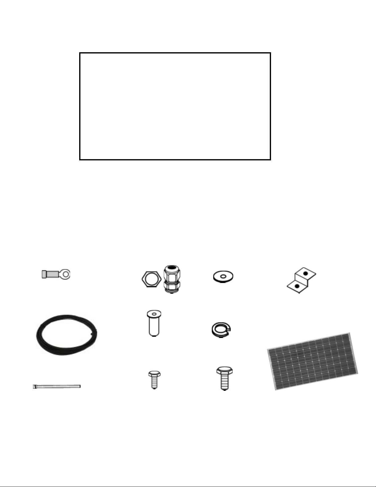
PART
01. Ring Terminal Battery Connector
02. Power Cable (7 m)
03. Tie Wrap
04. Connector & lock nut
05. #10/32 Well Nut
06. #10/32 Bolt
07. #10/32 Flat Washer
08. #10/32 Lock Washer
09. 1/2” Bolt
10. Mounting Feet
11. Solar module
12. SG-4 Regulator
Snowbird BP75MONO Freedom
RV-10
RV-20
2
2
1
1
6
6
1
1
4
4
8
8
8
8
8
8
4
4
4
4
1
1
1
-
Parts Checklist
01
02
03
04
05
06
07
08
09
10
11
www.gpelectric.com
3
Page 4
RV Kit InstallationRV Kit Installation
RV Kit Installation
RV Kit InstallationRV Kit Installation
1.0 Installation Overview
Congratulations on your purchase of a Go Power! Electric RV Solar Power Kit. You have
chosen a clean, quiet and sustainable way to provide power to your recreational vehicle.
A Go Power! Electric RV Solar Power Kit gives you the ability to dry camp while ensuring
your batteries remain fully charged. The Go Power! Electric RV Solar Power Kit allows
you to enjoy the luxuries and necessities that electricity provides, with or without a
campsite hookup. For simple battery maintenance to full-time live-aboard power, Go
Power! Electric RV Solar Power Kits are available in a variety of sizes and can be
installed on RVs, campers, trailers, 5th wheels and motor homes.
1.1 How Does the Go Power! Electric RV Solar Power Kit Work
The solar module converts a portion of the sun’s energy into DC electricity and this
electricity or specifically the current travels to the battery via a conductor, usually
copper wire. The battery stores the current as amperage, similar to a water tank
storing water. A battery is also designed to produce voltage which, when combined
with amperage, gives power. The battery power may be used at any time to operate
devices connected to the battery. When a battery is receiving and storing current from
the solar module, the battery is referred to as being charged or charging.
Please read and understand all instructions before installing your new product for the
easiest and safest installation. Before installing the kit, please review the installation
design included in this Installation Manual. If you have any doubts as to this kit’s
sustainability or compatibility with your RV, please contact your authorized Go Power!
Electric RV Dealer. It is advisable to retain this manual for future reference.
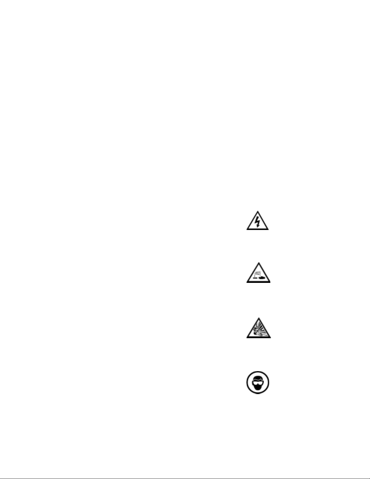
1.2 Warnings
Electrical Safety
Disconnect all power sources before attempting installation. Electricity can be very
dangerous. Installation should be performed only by a licensed electrician or qualified
personnel.
Solar Module Safety
Photovoltaic modules generate DC electricity when exposed to sunlight or other light
sources. Contact with the electrically active parts of the module, such as terminals, can
result in burns, sparks and lethal shock whether the module is connected or disconnected.
When modules are connected in parallel, amperages are additive. Consequently, a
system assembled from photovoltaic modules can produce high amperages, which
constitute an increased hazard.
Do not touch terminals while module is exposed to light. Cover the module face
completely with opaque material to halt the production of electricity when installing or
working with modules or wiring.
Battery Safety
Observe all safety precautions of the battery manufacturer when handling or working
around batteries. When charging, batteries may produce explosive hydrogen gas. Work
in a well ventilated area and use caution when making or removing electrical connections.
Ensure wires are disconnected from their power sources when wiring. Do not expose
battery to open flame, cigarettes, or sparks. Shield skin and eyes from battery acid.
Wiring Safety Ensure all connections are tight and secure. Loose connections may
generate sparks.
Work safely Wear protective eyewear and appropriate clothing during installation.
Use extreme caution when working with electricity and when handling and working
around batteries. Use properly insulated tools only.
4
www.gpelectric.com
Page 5

RV Kit InstallationRV Kit Installation
RV Kit Installation
RV Kit InstallationRV Kit Installation
Observe correct polarity at all times. Any contact in reverse polarity, however
brief, will cause the regulator and/or inverter fuse to blow and may damage the unit.
1.3 T ools Required (Additional tools may be required)
a. Slot Screwdriver
b. # 2 Robertson Square Head Screwdriver
c. Keyhole saw
d. Punch or Awl
e. Pliers
f. Wire Strippers
g. Wire crimpers
h. Electric hand drill
i. 1/16 and 3/8 inch drill bit
j. 5/16 and 7/16 inch wrench
k. Sealant
2.0 Wiring the Solar Module and Power Cable
1. Remove the module’s Junction Box cover. Remove the knockout on the Junction
Box for the connector and power cable. In some cases the connector may have
already been factory installed. To remove the knockout on the Junction Box, hold a
screwdriver tip against the knockout and strike sharply.
2. Strip back 2” of sheathing from the power cable. Insert the stripped back end of the
power cable through the connector and into the junction box. Secure the black wire
under the screw on the positive terminal, and the white wire under the negative
terminal. If the power cable consits of red and black wire, then the red is positive
and the black is negative. Ensure that all the wiring connections are tight. Replace
the Junction Box cover.
The RV-10 and RV-20 Modules are covered by a 5-year limited warranty.
Refrigerator
Vent Cover
Solar
Module
Method
2
Cable
Clamps
Method
Vent
Screen
1
Figure 1
Caution:
The screen may have sharp edges or
burrs.
3.0 Routing Power Cable through the Fridge Vent
Locate the refrigerator vent on the roof of the RV. Remove vent cover to gain access to
the duct opening. Refer to Figure 1. Retain vent-fastening hardware.
3.1 Method 1 – Hole in Side of Vent
Drill a hole through the side of the vent (5/8” hole). Insert a rubber grommet (not
included) into the hole. Insert the power cable (already wired to the solar module)
through the hole and carefully route it to the battery. Be certain to leave enough slack
to allow cable routing from module to vent along desired path.
3.2 Method 2 – Through Screen Grid
1. Thread the power cable (already wired to the solar module) carefully through the
screen and into opening. Enlarge screen grid hole if necessary.
2. Avoid strapping the power cable to existing wire between the module and the battery.
Allowing a few inches of space between the power cable and existing wire will
lessen the chance of voltage loss through thermal conduction. Use cable clamps or
tie wraps every few feet along RV roof and interior route to battery.
3. Ensure all penetrations into the RV roof are watertight. Use an appropriate sealant
as recommended by your RV Dealer to seal holes wherever necessary.
4. Replace vent cover.
4.0 Mounting the Solar Module
Cover the entire module with opaque material to prevent the danger of shock during
installation. Do not remove the material until the installation is complete. The solar
modules may be mounted to the roof using the included mounting feet.
www.gpelectric.com
5
Page 6

RV Kit InstallationRV Kit Installation
RV Kit Installation
RV Kit InstallationRV Kit Installation
1/4’ Bracket
Bolt
Solar
Module
4.1 Using the Mounting Feet
1. Assemble the mounting feet onto the ends of the solar module using the 1/4” bolts,
washers and nuts as shown in Figure 2.
2. Tighten nuts securely using a 7/16” wrench.
3. Place the module in a location that follows the criteria listed here:
• Select a location where the mounting surface is at least 1/2" thick and strong
enough to support mounting hardware, the solar module and wind loads.
• Minimize distance between the location of the solar module and the location
where the power cable will enter the vehicle to connect to the battery.
• Place the module lengthwise along the roof to reduce wind loading on vehicles
(if applicable).
• Avoid internal wiring when selecting the spots for drilling the four mounting
holes.
• Ensure obstacles, such as air conditioners, will not shade the solar module.
* Place module so that you have room to expand the current system if needed.
4. Mark the mounting hole locations by using a pencil to trace through the holes in the
mounting feet. Drill mounting holes only one inch deep with a 3/8” drill bit.
5. Use the appropriate sealant as recommended by your RV Dealer to ensure a
watertight installation.
6. Gently insert the well-nuts into the drill holes so that only the topmost flange part
remains above the roofline. Be careful not to push well-nuts through the holes.
7. Insert screws with lock washers and tighten. Do not overtighten.
Mounting
Foot
RV
Roof
RV
Roof
Positive
Connection
1/4” Nut
Figure 2Figure 2
Figure 2
Figure 2Figure 2
Solar
Module
Mounting
Foot
Figure 3
Common RV BatteryCommon RV Battery
Common RV Battery
Common RV BatteryCommon RV Battery
ConfigurationsConfigurations
Configurations
ConfigurationsConfigurations
Negative
Connection
1/4” Flat
Washer
1/4’
Lock
Washer
Installing a BD-3 or RegulatorInstalling a BD-3 or Regulator
5.0
Installing a BD-3 or Regulator
Installing a BD-3 or RegulatorInstalling a BD-3 or Regulator
RV-10
The RV 10 Kit includes a BD-3 (diode and inline fuse) to be connected on the positive
wire of the power cable. Use the included butt splice for this application.
The 3/8 ring terminal end of the BD-3 must be connected to the positive battery
terminal or the reverse diode protection will not work and the battery will not
charge. The RV-10 Kit does not include a regulator.
RV-20
The RV-20 Kit includes a regulator. Select a suitable location for the installation of
the regulator. Run the power cable from the solar module to the location selected.
Please refer to the regulator instruction manual for installation instructions. It is
recommended to put a 5 Amp inline fuse within 12 inches of the battery on the
positive wire between the regulator and the battery.
6.0 Connecting to the Battery & Solar Array
It is recommended to connect directly to the battery wherever possible.
1. Clean all corrosion from battery terminals before proceeding. Crimp the included
ring terminals onto the negative and positive wires of the power cable to be attached
to the battery. The RV-10 Kit will have the BD-3 crimped to the positive wire of the
power cable.
2. Attach the negative wire’s 3/8” ring terminal to the RV battery first. Check all electrical
connections and apply a protective coating to battery terminals.
6.1 Typical Battery Connection
1. Single 12 Volt battery connection (See Figure 4)
2. Multiple 12 volt battery connection. (See Figure 5)
3. 6 volt battery connection. (See Figure 6
Single 12 Volt Battery
12 Volt Configuration
Figure 4Figure 4
Figure 4
Figure 4Figure 4
Positive
Connection
T
12 Volt Parallel Configuation
Connection
wo 12 Volt Batteries
Figure 5Figure 5
Figure 5
Figure 5Figure 5
Positive
Negative
Connection
Negative
Connection
T
12 Volt Series Configuation
6
www.gpelectric.com
wo 6 Volt Batteries
Figure 6Figure 6
Figure 6
Figure 6Figure 6
Page 7

RV Kit InstallationRV Kit Installation
RV Kit Installation
RV Kit InstallationRV Kit Installation
7.0 Limited Warranty
1. Go Power! Electric Inc. warrants the Go Power! Electric RV Solar Power Kit for a
period of one (1) year from the date of shipment from its factory. This warranty is
valid against defects in materials and workmanship for the one (1) year warranty
period. It is not valid against defects resulting from, but not limited to:
• Misuse and/or abuse, neglect, or accident.
• Exceeding the unit’s design limits.
• Improper installation, including, but not limited to, improper environmental
protection and improper hook-up.
• Acts of God, including lightning, floods, earthquakes, fire, and high winds.
• Damage in handling, including damage encountered during shipment.
2. This warranty shall be considered void if the warranted product is in any way opened
or altered. The warranty will be void if any eyelet, rivets, or other fasteners used to
seal the unit are removed or altered, or if the unit’s serial number is in any way
removed, altered, replaced, defaced or rendered illegible.
3. The one (1) year term of this warranty does not apply to equipment where another
manufacturer’s warranty is available. This may include but is not limited to, the
charge controller, the solar modules and the inverter. The time limit for this warranty
may be for more or less than the Go Power Electric Inc. limited warranty. Go Power
Electric Inc. will assist the claimant in attempts to seek warranty claims for such
equipment.
7.1 General Warranty Issues
Refer to the manufacturer’s warranty sheet(s) where applicable.
1. Go Power Electric Inc. cannot assume responsibility for any damages to any system
components used in conjunction with Go Power Electric Inc. products, nor for claims
for personal injury or property damage resulting from the use of Go Power Electric
Inc. products or the improper operation thereof or consequential damages arising
from the products or use of the products.
2. Go Power Electric Inc. cannot guarantee compatibility of its products with other
components used in conjunction with Go Power Electric Inc. products, including, but
not limited to, solar modules, batteries, and system interconnects, and such loads
as inverters, transmitters, and other loads which produce “noise” or electromagnetic
interference, in excess of the levels to which Go Power Electric Inc. products are
compatible.
3. Warranty repair and/or evaluation will be provided only at the Victoria, British
Columbia facility of Go Power Electric Inc. Units for such repair and/or evaluation
must be returned freight prepaid to Go Power Electric Inc. with a written description
of any apparent defects. An RMA # issued only by Go Power Electric Inc. must be
clearly visible on the outside of the returned package. Go Power Electric Inc. will
not be required at any time to visit the installation site wherein Go Power Electric
Inc. products are subject to warranty repair and/or evaluation.
4. Only Go Power Electric Inc. is authorized to repair any of its products, and they
reserve the right to repair or replace any unit returned for warranty repair. The
party returning a unit for repair is responsible for proper packaging and for shipping
and insurance charges, as well as any other charges encountered, in shipping to
and from Go Power Electric Inc.
5. The purchaser’s exclusive remedy for any and all losses or damages resulting from
the date of sale of this product including, but not limited to, any allegations of
breach of warranty, breach of contract, negligence or strict liability, shall be limited,
at the option of Go Power Electric Inc., to either the return of the purchase price or
the replacement of the particular product for which claim is made and proved. In
no event shall Go Power Electric Inc. be liable to purchaser or purchaser’s customers
or to anyone else for any punitive, special, consequential, incidental or indirect
losses or damages resulting from the sale of the product, whether based upon loss
of goodwill, lost profits, work stoppages, impairments of other goods, breach of
contract, or otherwise.
6. This warranty supersedes all other warranties and may only be modified by statement
www.gpelectric.com
7
Page 8

RV Kit InstallationRV Kit Installation
RV Kit Installation
RV Kit InstallationRV Kit Installation
in writing, signed by Go Power Electric Inc.
7. Warranty terms effective as of January 2, 2004.
7.2 Repair and Return Information
To return items:
1. Call your Go Power Electric Inc. sales representative or Go Power Electric Inc.
Technical Support (1-866-247-6527) to try and troubleshoot the problem.
2. Obtain an RMA # through your Go Power Electric Inc. sales representative or Go
Power Electric Inc. Technical Support.
3. Ensure the RMA # is clearly visible on the outside of the package, or THE PACKAGE
WILL BE REFUSED.
4. Ship to Go Power Electric Inc. PREPAID at the following address:
CANADA
Go Power Electric Inc.
1969 Keating Cross Rd.
Victoria, BC V8M 2A4
5. Do not ship product collect, unless approved by management prior to Go Power
Electric Inc. receiving said product, or THE PACKAGE WILL BE REFUSED.
6. Test items or items that are not under warranty, or units that are not defective, will
be charged a minimum bench charge of $50.00 US plus taxes and shipping.
7. A 15% restocking charge will be applied on goods returned and accepted as “new”
stock.
USA
Go Power Electric Inc.
340 El Pueblo Rd. Suite F
Santa Cruz, CA 95060
8.0 System Glossar y
Ampere A unit of electrical current. Designates the number of electrons flowing per
second through a conductive material.
Ampere-Hour (Ahr or amp hour): A unit of energy, typically referring to battery
capacity. One ampere of current flowing for one hour.
Azimuth of the Sun: The angular measure between due south and the point on the
horizon directly below the sun.
Array: A number of photovoltaic modules electrically connected to produce a single
electrical output.
Angle of Incidence: The angle between a ray of sunlight striking a surface and a line
perpendicular to that surface. Rays perpendicular to a surface have a zero angle of
incidence.
Battery: Two or more electrochemical cells connected to provide energy storage.
May be used to designate one cell. PV system batteries may be “sealed” or “flooded”.
Blocking Diode: A diode application that prevents a battery from discharging through
the array at night or if the array becomes shaded. Most charge controllers are equipped
with a blocking diode.
Charge Controller (regulator): The PV system component that controls the battery’s
state of charge. It may also provide other system control functions. Also known as a
regulator.
Charge Rate: The current applied to a battery to restore its energy capacity. The
battery manufacturer will usually have a recommended charge rate for their product.
The rate is typically 10 –20 percent of the amp hour capacity at the 20-hour rate.
8
www.gpelectric.com
Page 9

RV Kit InstallationRV Kit Installation
RV Kit Installation
RV Kit InstallationRV Kit Installation
Current: DC or Direct Current is the type of electron flow provided by a battery or
solar cell, which flows in one direction. The unit for current is ampere or amp for short
and designated by the letter A.
Cycle: One battery cycle equals one discharge and one charge.
Deep Cycle Battery: Batteries that are designed to discharge as much as 80% of
their capacity as opposed to engine-starting or shallow cycle batteries which are designed
for heavy cranking but will not stand up to repeated deep discharges.
Depth of Discharge: A measure of how much energy has been withdrawn from a
battery, expressed as a percentage of full capacity. A 100 Ahr battery from which 30
Ahr has been withdrawn has undergone a 30% depth of discharge (DOD). This term is
the inverse of state of charge (SOC); the example battery would be at 70% SOC.
Diode: A semi-conductor device that allows current to flow in one direction only.
“Blocking diodes” and “isolation diodes” are standard diodes that have specific
applications.
Electrolyte: Battery acid.
Equalization: The process that equalizes the specific gravity of all the cells in a
battery by means of a controlled overcharge that breaks down sulfation on the battery
plates. Most inverter/chargers and some charge controllers are equipped with this
feature. Usually performed only on flooded batteries.
Flooded or Wet Cell Batteries: The most common type of PV battery. Battery caps
may be removed to expose the electrolyte inside the battery. Need proper ventilation
due to gassing and may need to be topped up with distilled water at regular intervals.
Grid-Connected: A power system interconnected with the grid (or mains) of the local
electric utility. Also referred to as utility-interactive or grid-tie.
Hybrid System: A power system consisting of two or more energy sources (e.g., a
PV array and a wind generator).
Hydrometer: A device used to measure the specific gravity (SG) of the electrolyte in
a flooded battery. A very accurate way to see the true charge of a battery.
Insolation: The solar energy received at a place over a given period. May be expressed
as sunhours per day, watts per square meter per hour, or any number of other units.
Inverter: A device that converts DC electricity to AC.
Isolation Diode: A diode application that prevents one segment of an array from
interacting with another array segment. Usually used in situations where two parts of
an array are facing in different directions therefore one part of an array may experience
shading while the other does not. Prevents array energy from flowing backwards through
a low voltage string of the array. May also serve the function of blocking diode.
Maximum Power (peak power): The point of a solar array, panel or module output
where the product of Imp and Vmp (Pmax, measured in watts) is maximized. The
points used to calculate Pmax are Imp (current @ max power) and Vmp (voltage @
max power).
Module: A number of solar cells electrically connected, and protected from the
environment usually by an aluminum frame covered with a pane of glass. A module is
self-contained and not sub dividable, therefore providing a single electrical output.
NOCT (Nominal Operating Cell Temperature): the temperature at which PV cells
in a module operate under Standard Operating Conditions (SOC), which are: irradiance
of 0.8 kW/m2, 20ºC ambient temperature, and average wind speed of 1 m/s, with the
wind oriented parallel to the plane of the array, and all sides of the array fully exposed
to the wind.
Open-Circuit Voltage (Voc): Refers to a photovoltaic device’s voltage potential when
it is disconnected from the rest of the PV system.
Panel: A group of photovoltaic modules (or single module) mechanically mounted on
a single frame.
www.gpelectric.com
9
Page 10

RV Kit InstallationRV Kit Installation
RV Kit Installation
RV Kit InstallationRV Kit Installation
Parallel Connection: Electrical connection where the positive terminals of a number
of devices are connected together, as are their negative terminals. The output voltage
is usually limited to the device with the lowest voltage, and the total current is the sum
of the current of all the devices.
Photovoltaic (PV): Capable of producing a voltage when exposed to radiant energy,
especially light.
Regulator: See “Charge Controller” definition.
Sealed Batteries: Electrolyte will not spill out and gassing is kept to a minimum. A
sealed battery is maintenance free and may be installed in several orientations.
Series Connection Electrical connection where the positive terminal of one device is
attached to the negative terminal of the next in a series string; in this connection, the
string voltage is the sum of the device voltages and the string current is limited to the
current of the least productive device in the string.
Short-Circuit Current (Isc): Refers to a PV device’s current output when the positive
terminal is directly connected to the negative terminal.
Specific Gravity: In relation to a flooded battery, it is the density of the “electrolyte”
compared with the density of water thereby measuring the battery state of charge.
Standard Operating Conditions (SOC): A set of reference PV device measurement
conditions consisting of irradiance of 0.8 kW/m2, 20ºC ambient temperature, and
average wind speed of 1m/s, with the wind oriented parallel to the plane of the array,
and all sides of the array fully exposed to the wind.
Standard Test Conditions (STC): A set of reference PV device measurement
conditions consisting of irradiance of 1 kW/m2, AM 1.5, and 25ºC cell temperature.
Standalone System: A power system not connected to the utility grid (mains.)
Sometimes referred to as an autonomous system.
State of Charge: The percentage of energy in a battery referenced to its nominal full
capacity.
Sulfation: The formation of lead sulfate crystals on the plates of a lead-acid battery.
Normally used to refer to large sulfate crystals, rather than small crystals formed in
normal battery operation. The sulfate on the plates of a battery will harden if left in a
partially charged state, causing reduced battery capacity and shortening the life of the
battery. If caught in time, “equalization” will remove the buildup of sulfation.
Voltage: The electrical potential between two points. Voltage is analogous to water
pressure in that it pushes the electrons or current through a conductor. The unit for
voltage is volt and designated by the letter V.
10
www.gpelectric.com
Page 11

RV Kit InstallationRV Kit Installation
RV Kit Installation
RV Kit InstallationRV Kit Installation
www.gpelectric.com
11
Page 12

RV Kit InstallationRV Kit Installation
RV Kit Installation
RV Kit InstallationRV Kit Installation
12
www.gpelectric.com
Page 13

RV Kit InstallationRV Kit Installation
RV Kit Installation
RV Kit InstallationRV Kit Installation
www.gpelectric.com
13
 Loading...