

Page 1
Go Power! Manual
GP-Remote
Page 2

Go Power! Remote
Owner’s Manual
1.0 Locking Remote
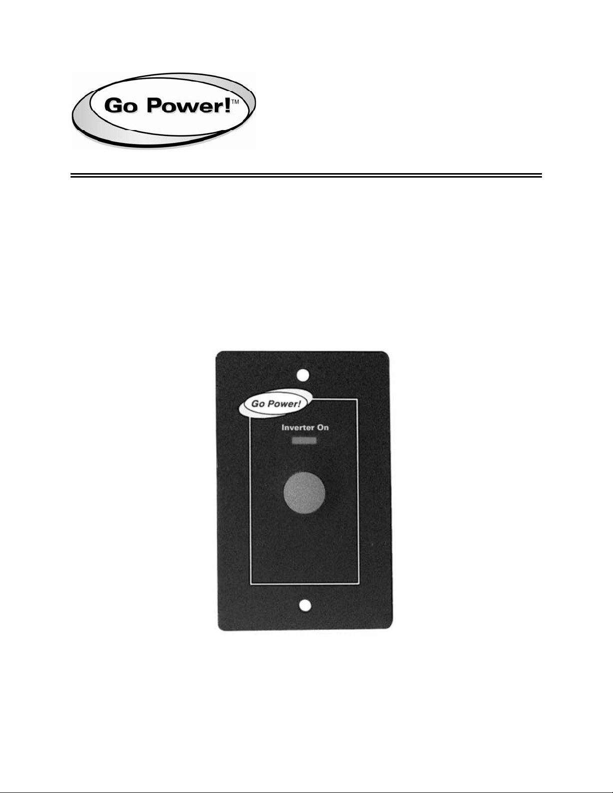
The GP-Remote can be used for the GP-1000, GP-1750 and GP-2500 inverters. It
features an LED indicator showing inverter status, on/ off switch and 25” cable that
simply plugs into the inverter.
1.1 Features
A: LED indicator
B: Push button
INVERTER ON
A
B
1.2 Indicator
Solid Green - Inverter “on”
No Colour - Inverter “off”
1.3 Functions
Short push (1 sec) - Inverter ON / OFF
2.0 Mounting a GP Remote
1. Cut out the template at right and position it on the wall where remote is to be
mounted.
2. Mark the location of the two holes, and the square area to be cut out. Note: Remote
switch assembly requires 3/4” (18mm) minimum clear panel depth.
3. Drill two holes, 1/8” (2.8mm) diameter and remove the cutout area.
4. Feed the phone jack connector and wire though the cutout hole in the panel and
route the wire to the inverter phone jack receptacle.
5. Position the remote switch assembly upright and secure to the panel using the two
screws provided. Plug the phone jack into the inverter. Press the button to turn the
inverter on and off.
2
Page 3

Go Power! Remote
Owner’s Manual
3.0 Mounting Template
3
Page 4

© 2008 Carmanah Technologies Corporation
www.carmanah.com
Go Power!
Building 4, 203 Harbour Road
Victoria, British Columbia
Canada V9A 3S2
Toll Free: 1.877.722.8877 | Fax: +1.250.380.0062
Email: info@carmanah.com
Number: GP_Remote_57152_Manual_vB
57152
 Loading...