


SY103-S06R-G2
Gooxi Micro Blade Server Barebone
User operation manual
Rev 0.1

Foreword
This manual is a micro-server barebones Gooxi SY103-S06R-G2 user's
operation manual. It mainly introduces and describes the characteristic
parameters, system configuration and installation method of this product. This
mini-server of Gooxi supports up to 3 nodes. The system is based on 1U3.
Chassis and G2SCN-4B motherboard integration.
This manual is for reference by professional system integrators and
personal computer technicians. This product should only be installed and
maintained by experienced technicians.
Manual framework
Chapter 1 Product Introduction
This chapter provides the specifications of the main components of the
system and describes the main features of the Gooxi G2SCN-4B motherboard and
the Goixi 1U3 chassis.
Chapter II System Interface Introduction
This chapter provides detailed description of the system interface, including
the main board's IO interface and each connector, terminal and jumper functions
and information.
Chapter 3 Detailed Node Installation
This chapter provides the processor, memory, hard disk installation and
description on the G2SCN-4B motherboard. Refer to this section when installing or
Shenzhen Gooxi Technology Co., Ltd.

removing the precautions for the processor, memory, hard disk, and heat sink.
Chapter 4 Server System Installation
This chapter describes the necessary steps and precautions for using the
SY103-S06R-G2 Micro Server barebones system.
Contents
Chapter 1 Product Introduction .......................................................................................................... 5
1.1 System Features ................................................................................................................. 5
1.2 Board Features .................................................................................................................... 7
1.3 server chassis System Features ..................................................................................... 8
1.4 System View ........................................................................................................................ 9
Chapter II System Interface Introduction ...................................................................................... 11
2.1 Overview ............................................................................................................................. 11
2.2 Motherboard IO Interface ............................................................................................ 15
2.3 Connection cable ............................................................................................................. 25
2.4 Jumper settings ................................................................................................................ 26
2.5 Power Module .................................................................................................................. 27
2.6 LED DEFINITIONS IN THE MOTHERBOARD .......................................................................... 27
Chapter 3 Detailed Node Installation ............................................................................................. 31
Shenzhen Gooxi Technology Co., Ltd.

3.1 CPU installation ................................................................................................................ 32
3.2 CPU Heatsink Installation ............................................................................................. 34
3.3 Memory Installation ....................................................................................................... 35
3.4 Hard Disk Installation ..................................................................................................... 37
Chapter 4 Server System Installation .............................................................................................. 40
4.1 Overview ............................................................................................................................. 40
4.2 System Steps ..................................................................................................................... 41
Shenzhen Gooxi Technology Co., Ltd.

Chapter 1 Product Introduction
Model
SY103-S06R-G2
processor
Intel Xeon processor E3-1200 V5/V6 series
Intel 6th Generation Core i3 series
Pentium series,Celeron series
Socket LGA1151 ,up to 80W CPU
Key
applications
Cloud computing server system
High performance computing server system
Database server system
Internet access server system
CDN acceleration
flow media services
Outstanding
features
Supports up to 3 hot-swappable node servers
The new giant 500W gold high efficiency power supply supports
1+1 redundancy
Each server node supports two 3.5-inch or four 2.5-inch SATA 3.0
6Gb/s hard disks
High-density, enterprise-class high-performance, cost-effective,
space-saving
IPMI 2.0 dedicated Gigabit management LAN per node
Six 4056 temperature-controlled fans make up 3 sets of
hot-swappable fan modules
Motherboard
G2SCN-4B
chipset
Intel PCH Lynxpoint C23X Series
Memory
(system)
The single-node theory supports 64GB ECC DDR4 UDIMMs, and
the system theory supports 192GB
Mezzanine
One Mezzanine 10Gb Connector for PCIE X8
PCIE
expansion
card
One Supports 1 Standard Transverse PCI-EX16 Expansion Card
M.2
Supports one PCIEX2 M.2 SSD and SATA M.2 SSD
SATA
Single-node C232 for 4*SATA3.0, C236 for 6*SATA3.0,
3.5 inch support RAID 0,1; 2.5 inch support RAID 0,1,5,10
1.1 System Features
1.1.1 System Parameters
Shenzhen Gooxi Technology Co., Ltd.
The system supports up to six 3.5-inch or 12 2.5-inch SATA HDDs
LAN
Single-node four Intel I210-AT 1GbE LAN Controller, the system
supports up to 12
HDMI
Aspeed AST2400 Graphics (VGA to HDMI)
Management
interface
IPMI 2.0 + KVM with dedicated LAN, Watch Dog,
power
supply
500W Gold High Efficiency Power Supply, Support 1+1
Redundant and Hot Swap Replacement
fan
Six 4056 fans (12V/Max 1.02A), composed of three
hot-swappable fan modules
Dimensions
1U Rack Mount, 800mm*448mm*43.5mm
1.1.2 System Overview
The Gooxi SY103-S06R-G2 Microblade Server Barebone is a high-density server
product (Micro-Cloud Server). This design supports hot plugging of three server
nodes in a 1U chassis height. Each node system can be used independently. You
can configure the number of server nodes as needed.
The main features of the product are summarized as follows:
Each server node supports two 3.5-inch or four 2.5-inch SATA hard
disks. The entire system supports a maximum of six 3.5-inch or twelve
2.5-inch hard disks.
The server system uses Intel Greenlow platform, with LGA1151 CPU,
supports Intel Xeon Processor E3-1200 V5/V6 series, and supports
80W Skylake series processors.
The system uses a 500W gold high-efficiency power supply that
supports 1+1 redundancy and hot swapping.
The system uses six 4056 fans to form three hot-swappable fan
modules.
Chipset uses the Intel PCH C23X chipset.
Shenzhen Gooxi Technology Co., Ltd.

Each node has 4 DIMM Dual Channel memories and supports 64GB
Motherboard
G2SCN-4B
processor
Intel Xeon processor E3-1200 V5/V6 series
Intel 6th Generation Core i3 series
Pentium series; Celeron series
Socket LGA1151 up to 80W CPU
chipset
Intel PCH Lynxpoint C23X
Memory
Single node supports up to 64GB ECC DDR4-1600/1866/2133
ECC UDIMMs.
Each node has four RJ45 Gigabit Ethernet ports for the Intel I210-AT.
The entire system is fully configured with 12 RJ45 Gigabit Ethernet
ports.
Each node has a multiplexed LAN that can be used as an IPMI
management network port for remote management. The BMC chip
uses the Aspeed AST2400.
Each node has an HDMI interface that is used to transfer the VGA
signal output of the BMC.
Each node has two USB 3.0 interfaces for users to use.
1.2 Board Features
1.2.1 Board Parameters:
The Gooxi SY103-S06R-G2 is fully equipped with a 3*G2SCN-4B
single-processor server board. It is based on the Intel X86 architecture, uses the
Intel Greenlow platform, is based on the Intel PCH C23X chipset, and is paired with
Inte's latest-generation Skylake CPU and supports dual-channel DDR4-.
1600/1866/2133 ECC UDIMM.
The following are the main features of G2SCN-4B:
Shenzhen Gooxi Technology Co., Ltd.

(system)
UDIMMs
SATA
Single-node C232 for 4*SATA3.0, C236 for 6*SATA3.0
3.5 inch support RAID 0,1; 2.5 inch support RAID 0,1,5,10
LAN
Single-node four Intel I210-AT 1GbE LAN Controller
VGA
Aspeed AST2400 Graphics
Input/output
interface
1*HDMI port, 4* Gigabit Ethernet port, one 1* mixed IPMI
network port, 1* motherboard switch
Management
interface
IPMI 2.0 + KVM with dedicated LAN;Watch Dog
Basic parameters
Chassis style
cabinet type
Chassis structure
1U
Adapt to the
G2SCN-4B
1.2.2 motherboard hardware chip features diagram:
1.3 server chassis System Features
1.3.1 Chassis Parameters
Shenzhen Gooxi Technology Co., Ltd.

motherboard
Hot-swappable
fans
stand by
cooling system
6 4056 temperature controlled fans
Supports sliding
rail
Optional
Cabinet fixing
Loose screws
product material
High quality SGCC (galvanized steel sheet)
Chassis size
800mm*448mm*43.5mm (length*width*height)
Package Size
1122*730*213MM (length*width*height)
Safety certification
CE、ROHS
1.3.2 System Power
The chassis is equipped with a 500W gold high-efficiency power supply,
supporting 1+1 redundancy and hot swapping;
Input AC voltage: 100V~245V;
Output DC voltage: +12v, +12v_SB;
Frequency: 47Hz~63Hz.
1.3.3 Heat Dissipation System
Six 4056 fans (12V/Max 1.02A) support hot-swappable replacement.
Fan parameters:
Voltage: 10.8~12.6V, current: 0.85A, maximum 1.02A.
Power: 10.2W, maximum 12.24W.
Maximum speed: 13600RPM front, 12400RPM rear.
Air flow: 0.8 m3/min (28.26 CFM), minimum 0.72 m3/min (25.43 CFM).
Pressure: MIN 340Pa, MAX 420Pa.
1.4 System View
1.4.1 Front View
Shenzhen Gooxi Technology Co., Ltd.
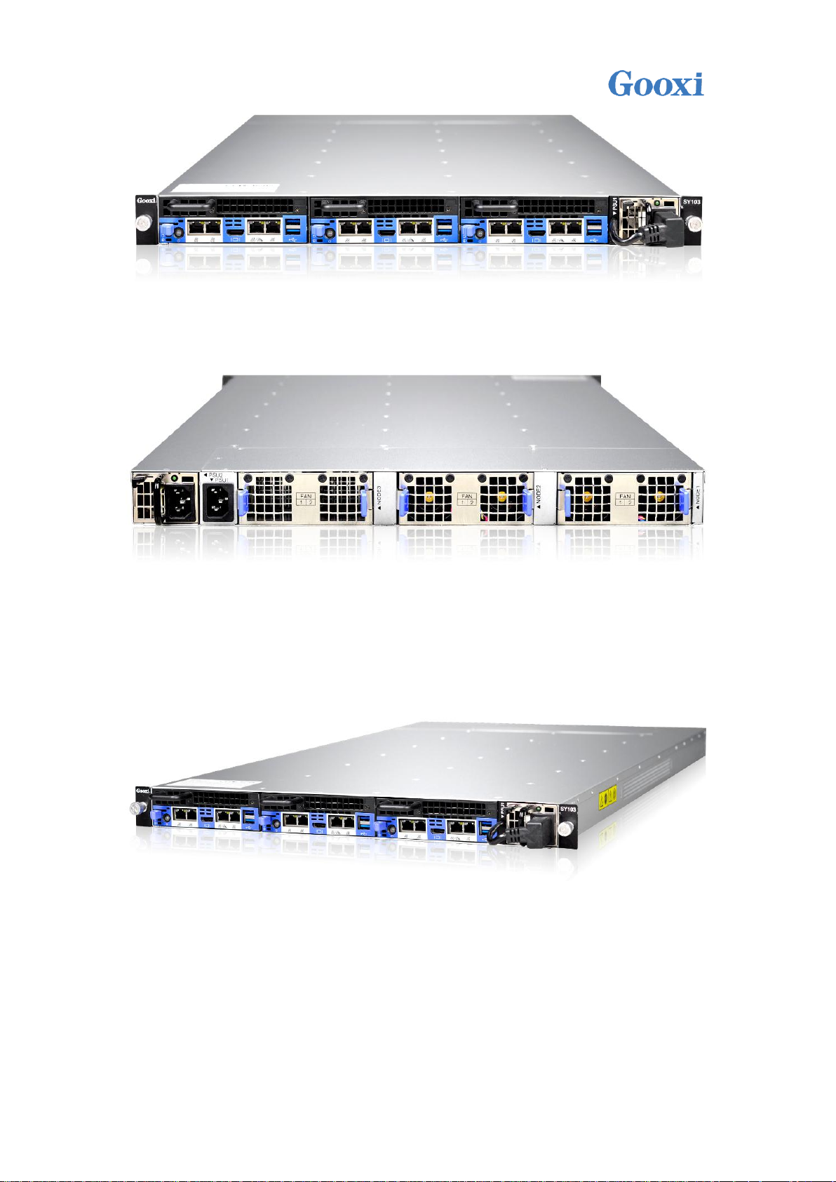
1.4.2 Rear view
1.4.3 Side view
/Precautions:
1. The above is a system view with three nodes and three nodes in total.
Users can, of course, choose the number of nodes they need based on actual
needs.
Shenzhen Gooxi Technology Co., Ltd.

2. When the system is configured with one or two nodes, the system fan must
have a minimum of two or four 4056 fans. If the number of nodes increases to three,
you need to add six system fans.
Chapter II System Interface
2.1 Overview
Introduction
The main board is the main component of the system. The main interface of the
system is on the main board. First of all, it is necessary to understand the interface
layout of the main board.
2.1.1 G2SCN-4B MOTHERBOARD REAL PICTURE
Shenzhen Gooxi Technology Co., Ltd.
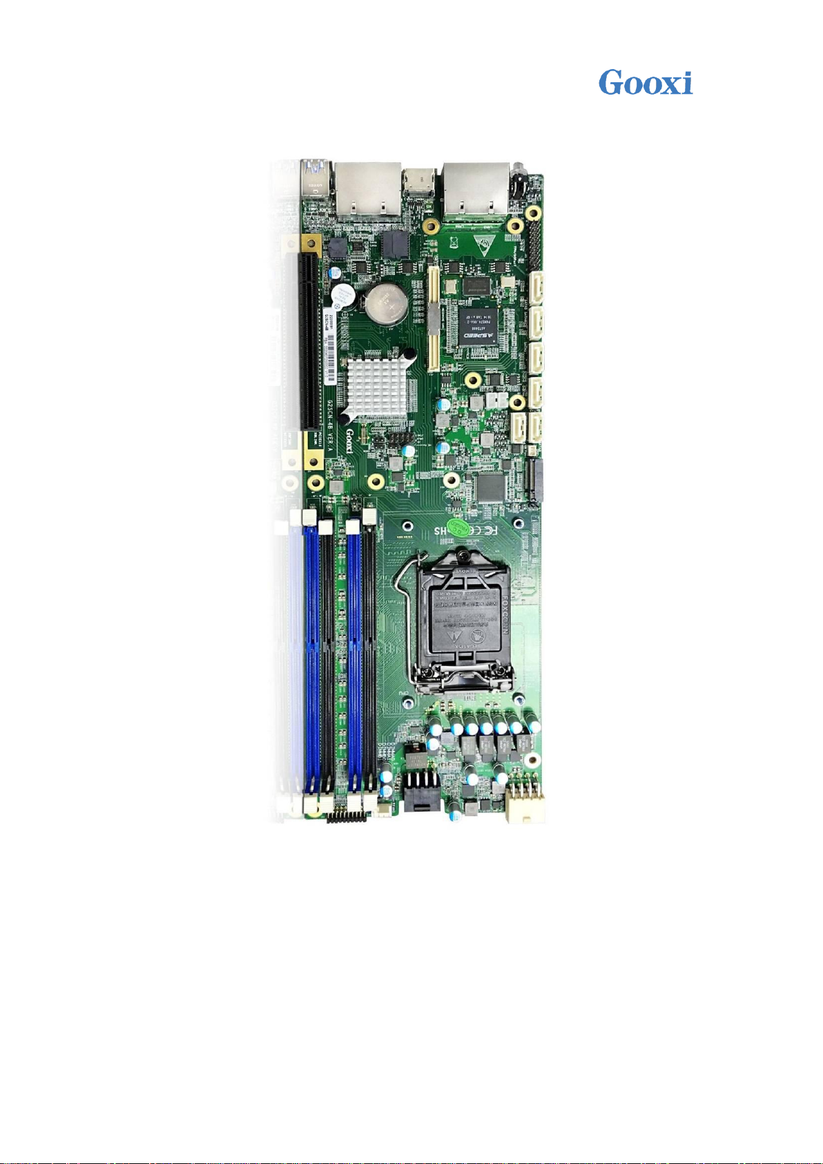
2.1.2 G2SCN-4B MOTHERBOARD INTERFACE AND DEFINITION:
1 MOTHERBOARD INTERFACE LOCATION DIAGRAM:
Shenzhen Gooxi Technology Co., Ltd.

2. Motherboard interface definition:
Shenzhen Gooxi Technology Co., Ltd.

Connector
name
(The upper
icon shows)
Connector function description
Board
position
FAN1
In-board fan connector, used only for CPU cooling during
debugging
FAN1
HDD Power
Black 8pin power connector for powering the hard disk
J2
PWR INPUT
White 8pin power connector, used to connect the power supply
from the adapter board to the motherboard
J1
M.2 SSD
75Pin M.2 SSD connector supporting PCIEX2 and SATA
specification M.2 SSD
J16
SATADOM
Power
3Pin External SATADOM Power Connector
J19
SATA1
PCH SATA3.0 Port2 7Pin Connector
SATA1
SATA2
PCH SATA3.0 Port3 7Pin Connector
SATA2
SATA3
PCH SATA3.0 Port4 7Pin Connector
SATA3
SATA4
PCH SATA3.0 Port5 7Pin Connector
SATA4
SATA5
PCH SATA3.0 Port6 7Pin Connector (C236 only)
SATA5
SATA6
PCH SATA3.0 Port7 7Pin Connector (C236 only)
SATA6
TPM/80Port
TPM/80Port pin can be used to connect TPM module or 80port
Debug running code card
J25
BMC UART
BMC debugging serial port
J22
SYS UART
BIOS (system) debugging serial port
J23
LAN1/NCSI
I210 1000M Data LAN port 1
Simultaneously use BCSI IPMI LAN port (100M) through NCSI
J17
LAN2
I210 1000M Data LAN port 2
J17
LAN3
I210 1000M Data LAN port 3 (This port is not available when
G2SCN-2B supports 10G card)
J18
Shenzhen Gooxi Technology Co., Ltd.

LAN4
I210 1000M Data LAN port 4 (This port is not available when
G2SCN-2B supports 10G LAN port)
J18
USB3.0
USB3.0 stacked double connector
J24
BATTERY
Lithium battery holder
J12
HDMI(VGA)
HDMI connector, but the actual signal is VGA, need to customize
HDMI to VGA Cable
J21
Mezzanine
Mezzanine connector, pin board connector to PCIEX8 signal, used
to plug 82599 million mega cards
The LAN3 LAN4 cannot be attached when the card is inserted, or
the mechanism interferes
J11
PCIEX16
PCIEX16 connector, actually with PCIEX8 signal, for PCIE riser card
J10
ME Update
For ME upgrade pin, insert jump cap effective
J15
Clear CMOS
Clear the CMOS pin, the default is not to take the jump cap, plug
in the jump cap is valid
J14
ME Recovery
Force the ME to restore to the default state. By default, skip caps
are not enabled.
J13
CPLD JTAG
CPLD JTAG connector for burning CPLD program
J3
DIMM A0
DIMM Channel A DDR4 SLOT0
J6
DIMM A1
DIMM Channel A DDR4 SLOT1
J7
DIMM B0
DIMM Channel B DDR4 SLOT0
J8
DIMM B1
DIMM Channel B DDR4 SLOT1
J9
Signal Pin Pin
2*10 20pin pin pin, used to transmit signal with MIB
J26
2.2 Motherboard IO Interface
2.2.1 NODE BUTTON
Node switch button In the front of the chassis, press the button to start the
node system. The position indicates the blue arrow below
Shenzhen Gooxi Technology Co., Ltd.

The node button is the switch button and provides two kinds of system
LED color status
LED
description
Green light
1Hz blinks
Power AC power, the node is not turned on (the system is
plugged into AC power, the green light flashes after 30 seconds)
Green light
The node is operating normally
Orange light
Failure of the system, such as power supply, fan, motherboard,
etc. Details can be viewed on the IPMI management interface.
not bright
System power AC terminal is not connected
status indicators to realize the power on and off functions of the node. When the
system is in the power on state, press this button to open the host; if the system is
in the power on state, it is light. Touch this button, you can turn off the NODE
system; if the host is in the boot no system state, long press this button to force
shutdown.
/ Note: After the system is plugged into an AC power source, wait for the
green indicator light to flash, and then press this button to turn on the system.
2.2.2 NODE ID INDICATOR
The node ID indicator is designed to allow the user to more intuitively identify
which node the current operation is on. The specific location of the board on the
main board is as follows. On the back of the motherboard, the Bottom layer is
marked with the D14 position:
Shenzhen Gooxi Technology Co., Ltd.

2.2.3 HDD LED INTRODUCTION
The HDD LED is located next to the switch key on the mainboard. The blue
indicator light is used to reflect the active status of the hard disk. The specific
location is as follows. The D1 position is the HDD LED. When the hard disk has data
read and write, the indicator light is flashing; When no data is being read or written,
this indicator is off.
2.2.4 IPMI LAN PORT
This network port is shared by IPMI and LAN1. Using LAN1's NCSI function,
LAN1 can be used as a 100M BMC IPMI LAN in addition to its own 1000M data
network port. It can be used for IPMI remote management and can be accessed
using CAT5 and above cables. The switch can also be directly connected to the
customer's host, supporting Gigabit, 100M, and adaptive adjustment, but it can not
be used as a service data network port. The LED indicators of the network port are
as follows:
Shenzhen Gooxi Technology Co., Ltd.

IPMI LAN Port LED
LED
description
Left LED
Link status indicator:
1. Gigabit Link, green long bright
2 hundred mega Link, orange long bright
3. Ten Mega Link, LED is not bright
Right LED
Yellow light flashes when there is data activity
This indicator is off when there is no data activity
Location map:
Business Data LAN Port Led
LED
description
Left Led
Link status indicator:
2.2.5 LAN PORT
The mainboard provides four Gigabit Ethernet ports (J17/J18 locations). The
main chip adopts the Intel I210-AT, self-adaptive 1000M, 100M, and 10M. The
mainboard has four Gigabit service network ports for receiving/sending service
data. The CAT5 is used. And above the cable access switch, you can also directly
connect to the customer's host. The LED indicators of the network port are as
follows:
Shenzhen Gooxi Technology Co., Ltd.

1. Gigabit Link, long green light;
2. One hundred trillion links, orange long
bright;
3. Ten mega Link, LED is off;
Right Led
The yellow light flashes when there is
data activity;
When no data activity, the indicator does
not light;
/ Note: The two network port indicators are the same.
USB3.0/2.0 Connector
PIN sequence
description
PIN1,5
5V
PIN2,6
D-
PIN3,7
D+
PIN4,8
Ground
Network port location diagram:
2.2.6 USB INTERFACE
Two external USB 3.0 ports (J24 locations) are used to access USB 3.0 Type A
devices, such as USB keyboards, USB drives, etc. The following is the USB PIN angle
definition:
Location map:
2.2.7 HDMI DISPLAY INTERFACE
The on-board HDMI connector is actually a VGA signal and requires a
switching cable. In particular, Pin is defined as follows:
Shenzhen Gooxi Technology Co., Ltd.

The motherboard graphics chip uses AST2400, AST2400 built-in PCIE VGA
SATA Connector Pin Definition
PIN sequence
description
PIN1
Ground
PIN2
SATA HOST TX+
PIN3
SATA HOST TX-
PIN4
Ground
Controller, a 15PIN VGA Connector is used to access the HDMI display, output host
information, the location is as follows:
2.2.8 SATA INTERFACE
The motherboard design 6 SATA Connector, all from the Intel PCH, according to
the different Chipset, there are C232 and C236, if the motherboard with C232
Chipset, only SATA1 ~ SATA4 4 SATA Connector, SATA5 and 6 can not be used; if
with C236 Chipset, There are 6 SATA Connectors for SATA1~SATA6; the location
diagrams are as follows:
Shenzhen Gooxi Technology Co., Ltd.

PIN5
SATA HOST RX-
PIN6
SATA HOST RX+
PIN7
Ground
2.2.9 SATA DOM POWER CONNECTOR
SATA DOM POWER Connector Pin Definition
PIN sequence
description
PIN1
5V
PIN2
Ground
PIN3
Ground
ATX 8PIN POWER Connector Pin Definition
PIN sequence
description
PIN1
5V_SB
PIN2
12V
PIN3
12V
PIN4
12V
PIN5
Ground
PIN6
Ground
PIN7
Ground
PIN8
Ground
The motherboard design reserved 3PIN Power Connector for SATA DOM access
power. PIN is defined as follows:
2.2.10 PCIE 3.0 X16 INTRODUCTION
The motherboard has a built-in PCIE3.0 X16 Slot. However, the PCIE Slot signal
is a non-standard signal and cannot be inserted into a standard PCI-E card. You
need to use the Guoxin Self-developed Riser card for transfer.
2.2.11 ATX 8PIN POWER CONNECTOR (IN) INTRODUCTION
J1 is a white ATX 8PIN POWER Connector. It is connected to the MIB
motherboard adapter board through the 8PIN power cable. Its PIN is defined as
follows:
2.2.12 ATX 8PIN POWER CONNECTOP (OUT)
INTRODUCTION
J2 is a black ATX 8PIN POWER Connector. It is used to connect the SATA hard
Shenzhen Gooxi Technology Co., Ltd.

disk power connector to the hard disk through the power cable.
ATX 8PIN POWER Connector Pin Definition
PIN sequence
description
PIN1
Ground
PIN2
Ground
PIN3
Ground
PIN4
Ground
PIN5
12V
PIN6
12V
PIN7
5V
PIN8
5V
20PIN Header Pin Definition
PIN sequence
description
Note
PIN1
BMC_PWM0
Used to regulate the
speed of the backplane
fan
PIN2
BMC_I2C_SCL_3
I2C clock signal is used
to access the backplane
PIN3
FAN_TACH_0
Backplane fan speed
signal
PIN4
BMC_I2C_SDA_3
I2C data signals are used
to access the backplane
PIN5
NODE_ID_0
Used to identify the
NODE ID number
PIN6
PM2_SMB_ALERT_N
PSU2 alarm signal
PIN7
NODE_ID_1
Used to identify the
NODE ID number
PIN8
PM1_SMB_ALERT_N
PSU1 alarm signal
PIN9
NODE_ID_2
Used to identify the
NODE ID number
PIN10
BMC_I2C_SCL_5
I2C clock signal
2.2.13 20 PIN HEADER INTRODUCTION (J26 POSITION)
This connector is used to communicate with the MID motherboard adapter
board, the connector is 20PIN, spacing is 2.0mm pitch. The PIN signal definition
and location are as follows:
Shenzhen Gooxi Technology Co., Ltd.

PIN11
NODE_ID_3
Used to identify the
NODE ID number
PIN12
BMC_I2C_SDA_5
I2C data signal
PIN13
MISC_PS_ON
Switch signal
PIN14
LM25066_ALERT_N
Hot-Swap chip alarm
signal
PIN15
PM2_PRESENT_N
PSU2 in-position signal
PIN16
PM2_PWROK
PSU2 PWROK signal
PIN17
PM1_PRESENT_N
PSU1 in-position signal
PIN18
PM1_PWROK
PSU1 PWROK signal
PIN19
Ground PIN20
3V3_SB
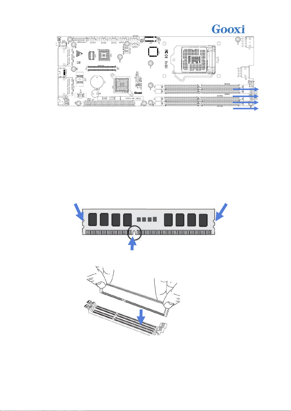
2.2.14 INTRODUCTION TO DIMM SLOT (J6/J7/J8/J9
POSITION)
The board is designed with four DDR4 SLOTs, which are divided into Channel A
and Channel B. Each channel has two DIMM SLOTs, J6 and J7 are Channel A DIMM
slots, and J8 and J9 are Channel B slots.
/ Note: If only one DIMM is inserted in each Channel, it needs to be inserted in
the slot away from the CPU.
Shenzhen Gooxi Technology Co., Ltd.

2.2.15 CPU SOCKET INTRODUCTION
The following figure shows the LGA1151 CPU SOCKET used to load the
LGA1151 CPU. During the installation of the CPU, attention should be paid to the
installation of the first PIN. The first PIN is as follows: The red circle below shows the
first PIN, as shown by the triangular arrows. Corresponding to the CPU triangle
arrow.
Shenzhen Gooxi Technology Co., Ltd.

2.2.16 M.2 DESIGN INSTRUCTIONS:
The motherboard supports M.2 KeyM SSD, 2242/2280/22110 three sizes, the
design supports PCIE SSD and SATA SSD.
When the PCIE SSD is plugged in, M2_SSD_TYPE is High to the PCH GPIO.
When the SATA SSD is low, the BIOS configures PICE0/SATA0 as PCIE or SATA by
checking the High Low of this GPIO.
2.2.17 MEZZANINE CONNECTOR:
Mezzanine connector. The pinch connector is connected to the PCIEX8 signal. It
is used to plug 82599 million mega cards. When inserting the card, LAN3 and LAN4
cannot be attached. Otherwise, the mechanism will interfere.
2.3 Connection cable
In the cable part, we have 5 different cables, which are 2 SATA high-speed cables, 1
motherboard to get 12V and 5V_SB electrical cables from the backplane, 1 cable to
transfer the motherboard 12V/5V power to the hard drive, and 1 cable 20-pin
motherboard and backplane signal communication cable.
Shenzhen Gooxi Technology Co., Ltd.

2.4 Jumper settings
G2SCN-4B single board 2PIN pin use
2PIN pin
number
description
default setting
J15
ME Update
No need to insert
jumper cap
J14
ME Recovery
No need to insert
jumper cap
J13
CMOS Clear
No need to insert
jumper cap
There are 3 2PIN pins in the G2SCN-4B motherboard. The following chart
shows the differences and functions of these 2PIN pins:
1. J15 introduction: Use 2PIN jumper cap to insert J15, short J15, close the
security mechanism of SPI FALSH ME at this moment, the user can upgrade ME
Firmware more, when need to upgrade ME, use for shorting.
2. J14 introduction: If you use a 2PIN jumper cap to insert J14, then short J14,
this will limit the function of the system to access the ME is limited, but the ME
Firmware update and upgrade is not limited, under normal circumstances, can not
be shorted.
3. J13 introduction: Use 2PIN adjustment cap to insert J13, then use Clear
CMOS.
The above 3 pin positions are as follows:
Shenzhen Gooxi Technology Co., Ltd.

2.5 Power Module
LED status description
LED
appearance
description
Green light
Power module is operating normally
Orange light
Power module alarm, may be over temperature, over
voltage, over current, or fan failure
Not bright or
off
AC power is not connected to the power module
UID LED description
The arrows in the above figure indicate the power module's LED indicators.
Each power module has its own status of the LED display, described in the following
table:
2.6 LED DEFINITIONS IN THE MOTHERBOARD
There are 6 LEDs in total on the mainboard. They are the three indicators at
Rear IO that indicate the UID LED of the main board ID and the HDD LED of the
main board's hard disk, three BMC heartbeat indicator LEDs, the motherboard
PWR OK LED, and the CPLD heartbeat indicator. .
1. UID LED
Shenzhen Gooxi Technology Co., Ltd.
D14
description
BMC(AST24
00)
The UID LED is the identity indicator on the motherboard.
The user can use the IPMI to control the indicator to be on or
off, and to be lit in blue.
It can be controlled by the front panel, specifically by
using a cable to connect to the front panel.
This LED can be turned on or off remotely through the
IPMI_LAN management network port. For example, when a
remote server detects an error on the server and needs to
enter the maintenance room, you can open the UID LED to
identify the problem board and then go to the computer
room to find the motherboard. Drop UID LED.
BMC Heart LED
D9
description
Green light flashes at 1Hz
Firmware initialization OK
This indicator cannot be lit
Firmware did not complete initialization
2. BMC Heart LED
3. Motherboard PWR OK LED
Shenzhen Gooxi Technology Co., Ltd.

PWR OK LED
D4
description
The green light stays on
Onboard power OK
This indicator cannot be
lit
Board power is not OK
Board CPLD Heartbeat LED
status
LED description
Location
CPLD program is
normal
Green LED 1HZ blinks
D19
CPLD is not
programmed or
abnormal
Green LED is off off state
Onboard power
OK
Green LED (D4) is always on green
D4
Board power is
not OK
Green LED (D4) is off off state
4. Board CPLD Heartbeat LED
5. Board Power OK LED
Shenzhen Gooxi Technology Co., Ltd.

Board PWR OK LED
status
LED description
Location
SATA HDD/M.2 SSD in place but
no data activity
Green LED is always
green
D5 (front)
SATA HDD/M.2 SSD has data
activity
Green LED blinks
SATA HDD/M.2 SSD is not in
place
Green LED off
Shenzhen Gooxi Technology Co., Ltd.

Chapter 3 Detailed Node
Installation
This chapter describes the installation steps of the main components on the
Shenzhen Gooxi Technology Co., Ltd.

system node, including the CPU, heat sink, memory, hard disk, and other
installation instructions.
3.1 CPU installation
/Precautions:
1. Please purchase INTEL CPU through formal channels.
2. Please make sure that the purchased processor specifications belong to
this system's support type.
3. If you purchased a CPU cooler separately, please make sure that you use
a Guoxin certified heat sink.
Detailed installation of LGA1151 processor steps:
1. Press gently on the platen and push outward (to the right) to unlock.
2. Once the platen handle is unlocked, gently lift the handle to open the
platen.
Shenzhen Gooxi Technology Co., Ltd.

3. Once the load board is open, use your thumb and forefinger to pinch the
north central edge of the CPU and the south central edge of the CPU, hold the
processor with your thumb and forefinger, and make sure that the socket's
alignment point aligns with the processor's gap. Place the processor straight into
the slot, do not lean or slide, and gently release the processor to make sure it seats
properly in the slot.
4. No effort is required to close the carrier plate. Press the carrier plate, close
and hold the socket lever.
Shenzhen Gooxi Technology Co., Ltd.

5. Once they are aligned, carefully insert the CPU straight down into the slot.
(To avoid damage to the CPU or socket, do not rub the surface of the CPU or any
pin sockets.)
6. For the CPU in place in the socket, check the four corners of the CPU to
ensure correct installation.
/ Warning: You can only install the CPU inside the socket in one direction to make
sure it is plugged into the CPU socket properly before closing the load board. If it
does not close properly, do not force it, as this may damage your CPU; instead,
check that the CPU is properly aligned and securely seated in the socket before
opening the platen.
3.2 CPU Heatsink Installation
1. Remove the heat sink and apply the appropriate amount of hot silicone
paste to the bottom of the heat sink.
Shenzhen Gooxi Technology Co., Ltd.

2. Place the heat sink on top of the CPU so that the four mounting holes are
aligned with the motherboard and the lower heat sink bracket.
3. First tighten the two diagonal screws until they are just in place (to avoid
damage to the CPU and heat sink, do not overtighten the screws).
4. Tighten the four bolts fully to complete the installation.
5. Reverse the sequence of this process to remove the heat sink.
3.3 Memory Installation
/ Note: When installing or removing DIMMs, prevent any possible damage to
DIMMs or their respective slots.
3.3.1 HOW TO INSTALL MEMORY
1. Motherboard DIMM slot order: DIMMA1, DIMMB1, DIMMA0, and DIMMB0,
pay attention to the memory slot is consistent with the DIMM slot gap to prevent
incorrect installation.
2. Vertically snap each DIMM module into place.
Shenzhen Gooxi Technology Co., Ltd.
3.3.2 MEMORY SUPPORT SPECIFICATIONS
DIMMA0
DIMMA1
DIMMB0
DIMMB1
The motherboard supports up to 1600/1866/2133 MHz of ECC DDR4 64GB
memory, has 4 DIMM slots, and uses the same size, type, and speed of DDR4
memory modules. The board will support the installation of one, two, or four
DIMM modules, and for the best memory performance it needs to be installed in
the same color slot as the DIMM.
Installation: Insert the memory module vertically and press the memory slot
snap position. Note the bottom of the alignment notch.
Gap
Notch
Simulate the demo diagram inserted into the memory bar:
Removal: Use your thumb to gently push the release tab near both ends of the
memory module socket to release the memory from the socket.
Simulate the demo picture of disassembling the memory:
Shenzhen Gooxi Technology Co., Ltd.

3.4 Hard Disk Installation
The system comes with three nodes, each node is on an sliding rail bracket, and
there is no cable design gold finger interface, which makes it easy to extract from
the system cabinet.
The hard disk is directly installed on the sliding rail bracket. For this reason,
hard disks are not hot-swappable. Each tray supports the installation of two 3.5”
hard disks or four 2.5” hard disks (2.5” hard disks are required for installing 2.5”
hard disks. Bracket).
1. Hold the release tab above the node, pull the node's handle, and pull it out
of the system.
2. The installed hard disk screw holes are aligned with those on the back of
the node sliding rail bracket.
The following figure shows the installation of a 3.5-inch hard disk:
Shenzhen Gooxi Technology Co., Ltd.

The following figure shows the installation of a 2.5-inch hard disk:
Shenzhen Gooxi Technology Co., Ltd.

3. Tighten the screws with a screwdriver to secure the hard disk to the sliding
rail bracket. The schematic diagram after installation is as follows. Take a 3.5-inch
hard disk as an example.
4. When the installation of the hard disk is complete, push the sliding rail
bracket back into the system enclosure, as shown in the following diagram:
3.5-inch hard disk for example.
Shenzhen Gooxi Technology Co., Ltd.

Chapter 4 Server System
4.1 Overview
Installation
This section describes the procedures for using the GOOXI SY103-S06R-G2
mini server barebone system.
Select an appropriate location on the cabinet to place the server system. This
location should meet the following conditions: clean, well-ventilated, dust-free or
dust-free areas, pay attention to avoid high temperatures, electrical noise and
electromagnetic interference, you also need Place a system-fitted power outlet
nearby.
Shenzhen Gooxi Technology Co., Ltd.
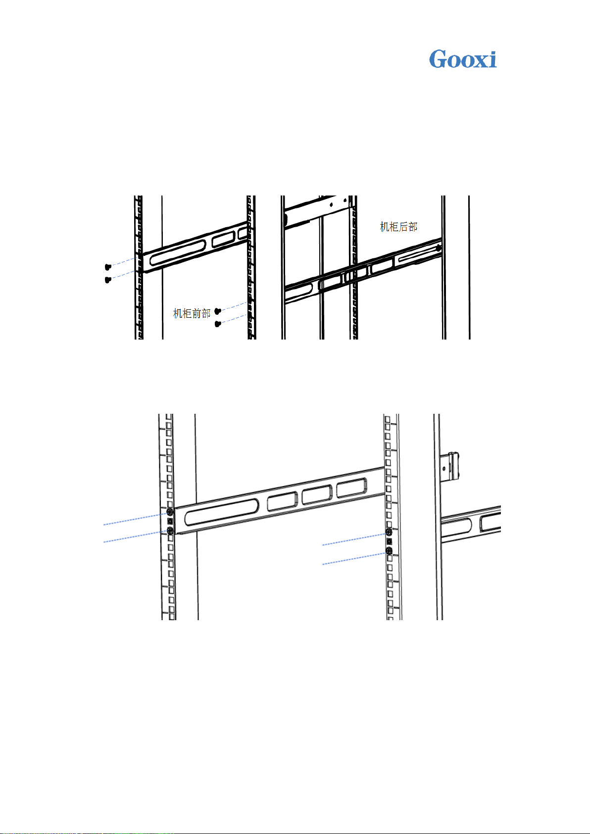
4.2 System Steps
GOOXI Rails Use the following steps to install the system into the cabinet.
1. As shown in the figure below, align the screw holes, and fix the two screws
on the front and back of each rail and the cabinet. The positions of the holes are the
same.
2. Tighten the screws and install the rails on the cabinet.
3. The final schematic diagram of the rail mounting to the cabinet is as
follows:
Shenzhen Gooxi Technology Co., Ltd.
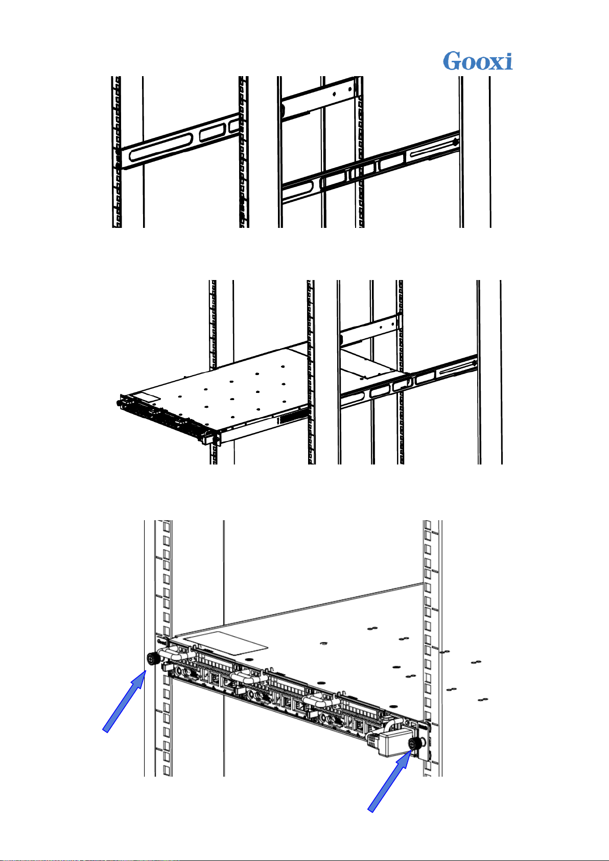
4. Hold the system up and place the system horizontally into the rails and
push it into the cabinet.
5. After the system is well-armed, lock the captive screws on the system panel,
as shown in the arrow below.
Shenzhen Gooxi Technology Co., Ltd.

system
System model
SY103-S06R-G2
System node
The system supports 3 nodes hot swap
CPU
Each node supports 1 CPU
hard disk
Supports up to 6 3.5-inch hard disks or 12 2.5-inch hard disks
RAM
Supports up to 192GB ECC DDR4-1600/1866/2133 UDIMMs
power supply
The system uses a 500W gold power efficiency power supply and
supports 1+1 redundancy
System size
800mm*448mm*43.5mm (deep * wide * high)
System weight
Net weight 14 kg, gross weight 17 kg
6. The final diagram of putting the entire server system into cabinet is as
follows:
/ Warning: Do not pull the handle of the server system. Otherwise, the
system will be pulled out from the cabinet, which may cause the system to
power off or down. The cabinet must be secured, and instability in the
cabinet may cause the cabinet to tip over.
The barebone parameters:
Shenzhen Gooxi Technology Co., Ltd.

System board
Motherboard
model
G2SCN-4B
CPU support
type
Intel Xeon processor E3-1200 V5/V6 series
Intel 6th Generation Core i3 ,i5,i7series
Pentium series;Celeron series
Socket LGA1151 up to 80W CPU
Motherboard
chipset
Intel PCH Lynxpoint C23X
Memory slots
Supports four 288 Pin DDR4 DIMM slots
Memory
support type
Single node supports up to 64GB ECC DDR4-1600/1866/2133
UDIMMs
Supports 4GB, 8GB, 16GB
SATA interface
Single-node C232 for 4* SATA3.0 or C236 for 6*SATA3.0,
3.5 inch support RAID 0,1; 2.5 inch support RAID 0,1,5,10
The system supports up to six 3.5-inch or 12 2.5-inch SATA HDDs
Hard disk
interface
features
Intel® RSTe Support software RAID 0, 1,5 & 10(for windows only)
Video card
Aspeed AST2400
IPMI
Support for Intelligent Platform Management Interface v.2.0
IPMI 2.0 with virtual media over LAN and KVM over LAN support
ASPEED AST2400 BMC
Network card
Four Intel I210-AT 1GbE LAN controllers
USB
2 USB3.0 interfaces, built-in 2 USB3.0 connector
DOM
Supports SATA DOM power connector
System power
Power supply
quantity
Support 2
Power
Features
The system uses a 500W gold power efficiency power supply and
supports 1+1 redundancy
Input voltage
100-240V 47Hz~63Hz。
The output
voltage
+12V,+5V_SB
System fan
Number of
fans
System supports 6 4056 temperature controlled fans
Shenzhen Gooxi Technology Co., Ltd.
Fan voltage
10.8-12.6V
Fan current
1.02A maximum
speed of the
fan
Maximum 13600RPM
Fan airflow
0.8 m3/min (28.26 CFM), minimum 0.72 m3/min (25.43 CFM).
Fan pressure
MIN 340Pa;MAX 420Pa
Operating system support
Server
Windows Server 2008 R2(64bit)
Windows SBS 2011 (64bit)
Windows Server 2012/2012 R2 (64bit)
Redhat Enterprise Linux Server (32bit/64bit)
Suse Enterprise Linux Server (32bit/64bit)
Ubuntu Server (32bit/64bit)
Virtualization
VMWare ESXi (Target)
Microsoft Hyper-V (Target)
Citrix Xen Server (Target)
Linux Kernel Virtual Machine (Target)
System ambient temperature
System
operating
temperature
Operating temperature: 10°C ~ 35°C; non-operating temperature:
-40°C ~ 70°C
System
temperature
and humidity
Operating humidity: 35%~80%; Non-operating humidity: 20% ~
90%
Safety certification
Certified
CE ROHS
Shenzhen Gooxi Technology Co., Ltd.
 Loading...