

シリコン
プレート(赤)
センサー
接続ピン
シリアル ナン バー ラベ ル
赤マーク
センサー
着脱ボタン
表面
OPEN
銘板ラベル
(英文)
電池フタ
裏面
■センサー
■本 体
■
LR6 1.5V
アルカリ乾電池 4 個
■
ユーザー登録カード/保証書
(日本国内用)
■
銘板ラベル(中文)
■
取扱説明書(和文
/
英文、英文/中文)
チップ
白被覆
表側
裏側
赤被覆
PAT.P
3 個
センサーの取付方向、裏表を間違えないように取
り付けてください。取付方向が逆 の場合、測定時
に温度が逆 方向に変化します。
セン サー 接 続ピ ンにしっか りとはまる ように 取り付 け
てください。センサーが破 損する恐れがありますので、
大きく曲げたり変形させな いようご注意ください。
後述 のセンサーアラーム機能をご使 用されている
場合、センサー交 換後に測 定モードにてセンサー
ダメージのリセット操作 をしてくだ さい。
センサーと電池は消耗品です。
設 定モ ード では POWER➊ボタンによる 電源
OF F と、オートパワーオフ機 能による電源の OF F
ができません。必ず測定モードに戻ってください。
セン サーを 正しく取り付け てから測 定してくだ
さい。左図のアラートが表示される場合は、
センサーが正しく接続されていないか、測定
物が測定可能温度外です。センサーの断線
や、ご使用の機器の設定を確認してください。
センサーの 寿命について、『350 ℃設定のこて先を 3 秒 測定す
る 条件 の 場合 20 0 回 』を 暫定 的 に目安 にしてい ます が、ご 使
用条 件により真のセンサー 寿命は大 きく変化します。セン サー
交 換 時 、 ダメ ー ジ 値 の リセ ット を 行 い 、ご 使 用 条 件 下 で の 寿 命
を把 握され た上で、設 定 値を変 更し有 効にご 活用くださ い。
セン サー のチップに、は んだの フラックス残 渣 や、こて先の
汚れ が付くとセンサ ーの 測定精 度が 低下します。定 期的には
んだ 吸 取線( CP
シリーズ
)などで除去してください。※チッ
プ上のはんだが不足していると、こて先によっては正しく温度
が 計 れな い 場 合が あり ます。使 用 されて いる こて先の 大 きさ
に合わせて、チップ上のはんだの 量を調整してください。
測定 を繰り返 すと チップが 損耗し、感 度が 低下します。正確
な温 度を 測定するた め、チップの損 耗したセン サーは、新し
いセ ンサ ーに交 換してくだ さい。 交換 時 期に関して は、下 記
セン サーアラーム機 能などを 活用くださ い。
取扱説明書
太洋電機産業株式会社
この説明書はなくさないように大切に保管してください。
この度は こて先温度計 TM -100 をお買いあげい
ただきましてありがとうございます。この製品をご使用
になる前に本取扱説明書を必ずお読み下さい。
注 意
備 考
誤った取扱いをしたときに、傷害また
は物的損害が発生する恐れがある場
合、本機の動作不良に結び付くもの。
取扱注意事 項アドバイスおよび、諸注
意 が 記載 さ れて いま す。
この説明書では注意事項を次のように区分しています。
注意事項について
目 次 2. 梱包内容/各部の名称
3. センサーの着脱方法
4. 温度の測定方法
5. 各種機能と設定
6. 交換部品/オプション
7. 操作一覧
1. 仕様
測定時、センサーへの加圧が強すぎると損傷の
恐れ があります。チップにこて先 が軽 くタッチす
る程 度でご 使用くださ い。
1.計測するこて先は高温状態になっています。取扱いを誤
ると、やけど・火災原因になりますのでご注意ください。
2. 加熱したこて先をセンサー部以外に接触させたり、ケー
スに温風をあてるなど、樹脂製ケースに熱負荷のかかる
使い方をしないでください。溶融・破損の原因となります。
3.繊細な部品を内装しております、本機を分解しないでく
ださい。
4. 静電気の影響で、電源が OFF の時でも LE D が点滅す
る事がありますが、動作に問題はありません。
5.本器の損傷を防ぐため、運搬および取扱いの際は振動、
衝撃を避けてください。特に、落下などによる衝撃に
注意してください。本器を破損します。
T M-10 0 用 替 セ ン サ ー( 3 個 入 )
TM-100S
センサープローブ(1個 入)はんだ槽用
TM-100SP
■ 1.仕様
■ 2.
梱包内容/各部の名称
■ 3.センサーの着脱方法
■ 4.温度の測定方法
■ 5.各種機能と設定
■ 6.交換部品
/
オプション
■ 7.操作一覧
注 意
注 意
注 意
備考
備考
備考
備 考
備 考
備考
Printed in Japan, JANUARY 2014 A9430AW00
www.goot.co.jp E-mail: info@goot.co.jp
東 京
03(3832)1774
大 阪
06(6644)3508
新 潟
0256(35)5379
広 島
084 (951)9010
お客様相談窓口
型 番 TM -100
電源 単3乾電 池
LR6×4本: 6V
外形寸法 83(W) x 41(H) x 140(D)mm
重量
150 g
(電池 除く)
温度分解能
1˚C
測定範囲
センサー
(TM-100S) : 0-500˚C(32–932˚F)
プ ローブ
(TM-10 0SP )
使用時
: 0–70 0˚C(32–1292˚F)
精度フルス ケールの ±
0.5%
(セン サー誤 差含 まず)
表示
LED
表示
動作環境
0-50˚C、 20-85%RH
(結 露なきこと)
型 番 TM -100 S
センサ ータイプ
Type K(CA
方式)
サイズ
9(W)×45(H)×3(D)mm
重量
0.8g
センサー
本体
取付方法
1. センサーの赤い被覆
側 を、シリ コン プレ
ー ト( 赤 ) 側 の セ ン
サー 接続ピ ンに取り
付 けま す。
A.測定モードの機能と操作方法
電源を ON すると常に測定モードからスタートします。測定モード
には次 のような 機能 があり ます。
(数値の切り替え・数値の設定は設 定モ ードで 行 い ま す 。)
・ピー クホ ールド 機能 (出荷時設定 :OFF)
測 定モ ードの とき、
PEAK HOLD/MODE SET ➌
ボタ ンを 押すと 、ホー
ルドラ ンプ
➏
が点灯し、常に計測温度の最大値が表示されるよう
にな ります。 もう一 度
PEAK HOLD/MODE SET➌
ボタ ンを 押すとピ
ークホールド機能が解除されます。
・オ ートパ ワー O FF 機能 (出荷時 設定 :60 秒)
電 源 ON 後、設 定時間 より長く測 定値 100 ℃以下 が続くと、電 源
OFF にします。電源OFF までの設定時間を 30 秒単位で変更可
能です(最大 300 秒)。測定モードで表示温 度が100℃以下の時、
設定 時間までに
SENSOR RESET➋
ボタン を押すこと で経 過時間
が リセ ットさ れ 、オ ート パ ワー O F F ま で の 時 間が 延長 しま す。
・セン サーアラーム(寿命 アラーム)機 能( P A T . P )(出荷時設定 :200 回)
350℃で 3 秒計測を 1単位として、当社独自の計算 方法によりセン
サーのダメージを秤量・積算し、設定された数値寿命に達したら、セ
ン サーア ラーム ランプ
➎
が点 滅する ことでセン サー交 換の大 まかな
時期を通知します。設定値を 0にすれば機能 OFF になります。
測 定モ ードで
SENSOR RESET ➋
を 3 秒 長押しす ることで積 算ダ
メー ジ 値 をリ セ ット( 0 復 帰 )し ま す。
・バッテ リーアラ ーム
電池 電圧 が規 定値 以下にな ると、バッテリーアラ ームランプ
➍
が点
滅し 、電 池交 換時 期を 通知 します。
2.センサー着脱ボタンを軽く押すと、シリコンプレート側の接続ピンが、
反対側のピン方向へ移動します。センサーの白被覆側をもう一方の
接 続ピ ンに 取り付 けま す。
取外方法
本体 をしっかりと保 持した
まま 逆さ まにし、セ ンサ ー
着 脱ボ タンを 数回 押すと 取
り外 すこと がで きま す。
1.
POWER
ボ タ ン を 押 すと、 設 定 単 位 摂 氏、ま たは
華氏を 表示します。その後、室温が表示されれば測定可
能 で す 。( 測 定 モ ー ド )
2. センサー のチップ上とこて先に 新鮮な はんだを 盛りながらこて先を チ
ップ に当 て、温 度が 安 定した 状態 で読 み取り ます。
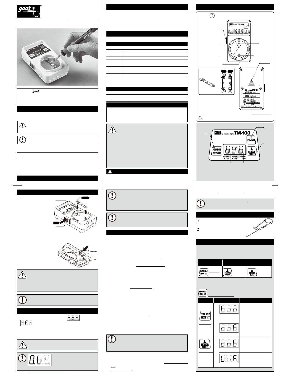
電源ボタン センサーリセット及び設定値ボタン
バッテリーアラームランプ
(点滅)
ピークホールド及びモード切替 ボタン
センサーアラームランプ(点滅) ホールドランプ(ON:点灯)
シリコン
プレート(赤)
センサー
着脱ボタン
押す
赤被覆
下に向ける
押す
ボタン操作 順 表示
項目の意味と設定域
オートパワーOFFまでの時
間( 秒 )を 設 定 し ま す。
設定範囲:0—300(30秒刻み)
出荷時 60、設定値 0 で機能
オフ になりま す。
摂氏(℃)/ 華氏(℉)の表示
を 設定 をします。
設定値 : ℃⇔℉の設 定されて い
る方 が点 灯します。
出荷時 ℃
セン サー 寿命 値を 設定 します。
設定範囲 : 0—500(50 回
刻み) 出荷時 200、
設定値
0 で 機能 オフに なります。
センサーの消耗換算値を表
示し ます。
セ ン サ ー ダメ ー ジリ セット を 行
うと0 を表示します。出荷時0。
ピー クホ ールド
ON/OFF
自動 OFF 時間延 長 セン サーダメー ジ
リ セ ット ( 0 復 帰 )
➔
➔ ➔➔
先頭に
戻る
項目送り
設定値変更
B . 設定モードの機能と操作方法
測 定モ ードで 、
PEAK HOLD/MODE SET➌
ボタン を 3 秒以 上長 押しす
ると 、設 定モ ードに なりま す。設 定モ ードで は、
PEAK HOLD/MODE
SET
➌
ボタン を押 すごとに、設 定項目 が切り替 わり、
SENSOR RESET➋
ボタ ンで 、設 定値 の変 更が 可能 です。
B . 設 定モード
A . 測 定 モ ード
PEAK HOLD/
MODE SET
ボタンを押す
PEAK HOLD/
MODE SET
ボタンを押す
電源 ON直後は、測定モードです。
「測定」と「設定」のモード切替は、両方向とも
PEAK HOLD/MODE SET
ボ タン を 3 秒以 上 長 押してく ださ い。
SENSOR RESET
ボタンを押す
SENSOR RESET
ボタンを
3 秒以 上長 押し
SENSOR RESET
ボタンを押す
校正について
購入日より 1 年間精度を保証致します。(日本国内は同梱の保証
書により保証しますので、ユーザー登録カードにご記入の上返
送ください。)保証期間以降も有償で校正を承ります。詳しくは
お客様相談窓口にお問い合わせください。
■パネル部の名称
TM-100SP
各機能の設 定方法は
[7. 操 作一 覧 ] をご参照ください。
設 定モ ードで 、
PEAK HOLD/MODE SET➌
ボタンを 3 秒以上 長押
しす ると 、測 定モ ードに 戻りま す。
付属の電池はテスト用です。
パネル部とピン下部の円板に透 明な保護シートがあります。
※
1000˚F
以上は
F-1
と下3桁を 交互に 表示しま す。
T M -10 0
こて先 温 度 計

安装时请不要弄错温度传感器的安装方向和正反面,
在安装反的情况下,测定的温度也会反方向变化。
请将温度传感器牢牢地安装在接头 上。请 不要用力弯
曲温度传感器,以免造成温度传感 器的破损。
在更换温度传感器后需要在测定模式里重置温度
传感器寿命的提示值。详情请见后边的温度传感器
寿命提示功能。
在设定模式下,如果只是按下 POWER➊关机,
不能关掉自动关机功能。一定要回到温度测定模
式再关机。
请正确地安装好温度传感器后再测定温度。显
示左图时,可能是温度传感器没有正确地安装
好或是测定温度在可测温度范围外。也请确认
温度传感器是否有断线。
关于温度传感器 的寿命,是以『焊嘴温 度 350°C,测定时间 3
秒为基准,可以使用 200 次以上』作为基准,根据不同使 用方法,
寿命 会有 较大的 差异。在 更换温 度传感器 时、需要 先重置 温度
传感器的寿命报警提示 值(归 0),根据具体的使用情况,请自
行设定温度传感器的寿命。
温度测定部如有助焊剂的残渣或焊嘴上的污垢,会造成温
度传感器的精确度下降。请定期使用吸锡线(CP 系列产品)
去除残渣。※如果温度测试部位缺少焊锡,就不能精确地
测定出焊嘴的温度。因此请根据焊嘴的大小调整测试部位的
焊锡量。
多次使用测定部会有所损耗、感应度会有所下降。为了能够
精确地测定温度、当温度传感器测定部损耗严重时,请更换
新的温度传感器。更换后,请使用下记的温度传感器寿命提
示报警功能。
使用说明书
太洋電機産業株式会社
请仔细保管此使用说明书,以便于日后查阅。
由衷感谢您购买这款
吉欧欧替
牌焊嘴温度计。请按照说
明书所记述的使用方法并请遵守注意事项。
注意
注意
备注
请使用正确的操作方法,以避免造成意
外的损伤和财产的损失。
各种注意事项和使用建议。
本说明书的注意事项有以下区分。
注意事项
目录 2. 包装内容 / 各部品的名称
3. 温度传感器的取出方法
4. 温度的测定方法
5. 各种功能和设定
6. 交换配件 / 选购配件
7. 操 作 方 法
1. 规格
测定温度 时,如果用力按压温度传感器可能会造
成损伤。请将焊嘴轻轻地放在温度测定部。
1. 测量的焊嘴处于高温状态。请注意不要错误操作、
否则可能会引起烧伤或火灾。
2.
请不要用高温的焊嘴接触温度传感器以外的部位,
也不要用热风等对树脂外壳加热,以免造成融化和
破损。
3. 本产品内含精密零件,请不要自行拆解本产品。
4. 因为静电的影响,即使关掉电源 LED 可能会有
闪烁,与产品质量无关。
5. 为了防止造成本机的损伤及破损,请在搬运及包
装时,避免振动、冲击。特别注意勿坠落。
T M-10 0 用 交 换 温 度 传 感 器( 3 个 )
TM-100S
温度探针(测量锡炉温度)
TM-100SP
■ 1. 规格
■ 2.
包装内容 / 各部品的名称
■ 3.
温度传感器的取出方法
■ 4. 温度的测定方法
■ 5. 各种功能和设定
■ 6. 交换配件 / 选购配件
■ 7. 操作方法
注 意
注 意
备注
备注
备注
备注
备注
备注
www.goot.cn E-mail: info@goot.cn
型号 T M-10 0
电源 5号干电池 × 4 只 :6 V
尺寸 83(W) x 41(H) x 140(D)mm
重量 1 5 0 g( 不包含电池)
温度分解度 1˚C
测定范围
温度传感器 (T M-10 0S) : 0–500˚C(32–932˚F)
使用温度 探针时 (T M-10 0SP) : 0–700˚C(3 2–1 2 9 2 ˚F
)
精度实际温度±0.5%以内(不包含温度传感器的误差)
显示 LED显示
作业环境 0−50˚C、 2 0−85%RH(无结露)
型号 T M-10 0S
温度传感器 类型
热电偶
K型(CA
方式)
尺寸 9 (W)× 45 (H)×3 (D )m m
重量 0.8g
温度传感器
本体
安装方法
1. 将温度传感器的红色
覆盖端 安装在红色垫
片处的温 度传感器接
头上。
A 测定模式的功能和操作方法
开机后显示温度测定模式。测定模式有以下功能。
(在设定模式里进行数值的切换,数值的设定)
・温度最高值记录功能(出厂时为关闭状态)
在温度测定模式下按 下
PEAK HOLD/MODE SET➌
、温度最高 值记
录灯
➏ 亮、即可显示出温度测定的最高值。再次按下 PEAK HOLD/
MODE SET➌,可解除此 功能 。
・ 自 动 关 机 功 能( 出 厂 时 的 设 定 :6 0 秒 )
开机后,超 过设定时间,且温 度在 100℃以下时会自动 关机。自动关
机时间以 30 秒为一单位改变(最大为 300 秒)。在温度测定模式下,
温 度在 1 0 0℃ 以下,按 下
▲SENSOR RESET➋ 按键可 延长自动关 机时
间。
・温度传感器提示(寿命提 示)功能(PAT.P)( 出厂时的设定 :200 次)
以焊嘴温 度 350℃,测定时间 3 秒为一个单位,根据我司的计算方法,
只要超过设定 好的次数,提示报警灯
➎ 就会闪烁告知温度传感器的
此次寿命完 结。将设定值归 0 就可以关掉此功能。在温度测定模式下,
长按
▲SENSOR RESET➋3 秒,可重置温度传感器寿命提示值(归 0)
・电 池寿 命提 示
电池量在低于规定值时,更换电池的报警提示灯
➍ 开始 闪烁、告 知需
更换电池。
2. 一直按压住温度传感器的取出按键,红色垫片处的温度传感器接头
移动靠近对面的接头。然后把温度传感器的白色覆盖端安装上另一
接头上。
取出方法
小心地拿住本产品然后正面
朝 下,按 多几 次 温 度传 感 器
取出按 钮后温 度传感器会自
动落 下。
1. 按下 POWER 键、LED 显示的设定单位 为
或华氏
華后,可测定室温。(温度 测定模式)
2. 烙铁头沾取一些焊锡后放在温度传感器的测定处,可精确稳定地测定出
温度。
电池寿命提示
记录温度最高值及模式切换
温度传感器寿命提示值重置温度最高值记录灯
电源
温度传感器寿命重置及设定值更改
按键操作 顺序 显示 项目意思和设定范围
设定关机时间。
设定范围:0 - 3 0 0(30秒为一 个
单位更改
)
出 厂值 为 60 秒, 更改 至 0 时,
此功能关。
设定显示温度单位摄氏(℃)
或华氏(˚F)。
设定:设定好的温度单位会亮灯。
(
出厂时为 ℃
)
设定温度传感器 的寿命
设定范围 :0 - 5 0 0(50 为一个
单位更改
)
。出 厂时为 2 00 ,更
改 至 0 时,此 功能关 闭。
显示温度传 感器计算出的已用
寿命次数
重置温度传感器寿命提示值
后,L IF 显 示为 0 。
记录温度最高值
开/关
延长自动关机时 间
温度传感器寿命 提示值
重 置( 归 0 )
➔
➔ ➔➔
回到最
上边
项目切换
更改设定值
B. 设定模式功能和操作方法
在温度测定模式下,长 按
PEAK HOLD/MODE SET➌ 3 秒以上,进入设
定模式。在设定模式下,每按下
PEAK HOLD/MODE SET➌,即可 切换
设定 项目。按下
▲SENSOR RESET➋,可改变设定值。在设定模式下、
长按
PEAK HOLD/MODE SET➌ 3 秒以上,回到温度测定模式。
B. 设定模式
A. 测定模式
PEAK HOLD/
MODE SET
按下按键
按下按键
按下按键
电源 ON 后,进入测定模式。
长按 3 秒
PEAK HOLD/MODE SET
按键,可进行测定模式
与设定模式之间的自由切换。
SENSOR RESET
按下按键
SENSOR RESET
长按 3秒
校正
购买后一年内保校正。一年后需收费。日本以外的客户请和代
理商或弊司的客户咨询服务窗口联系。
■操作面板的名称
TM-100SP
各种功能和设定方法请参照
(7 操作方法)
※ 1000˚F以上的 温度是F-1和 后3位 数交 替显示 。
红色垫片
温度传感器接头
序列号标签
红色标记
温度传感器的
取出按钮
正面
OPEN
规格标签
(英文)
电池后盖
反面
■温度传感器
■本体
■
1.5V 5号碱性干电池 4个
■
用户登陆卡/保证书
(日本国内使用)
■规格标签(中文)
■使用说明书(日语/英语,英语/中文)
温度测定部
白色覆盖端
正面
反面
红色覆盖端
PAT.P
( 3个)
按下
温度传感器的
取出按钮
红色垫片
红色覆盖端
朝下
按下
中国事务所
广东省深圳市南山区南海大道海王大厦A座
16C
邮编 :
5180 33
TEL:0755-2664-6936 FA X:0755-2664-6923
T M -10 0
焊嘴温度计
goot,
吉欧欧替
为太洋电机产业株式会社的注册商标。
配件的电池为试用品。
操作面板和温度测定部下方的银色圆板上都 贴有透明保护膜。
2014 年1 月印刷 A9430HT00
温度传感器和电池是消耗品。

Attach with correct orientation, and right side up.
Incorrect attaching will cause wrong temperature data.
Put the sensor on the connector pin firmly. To avoid
damaging the sensor, do not bend or deform it.
When using the Sensor-life Counter function (described later),
reset the sensor-damage value in measuring mode after
replacing with a new sensor.
Be sure to attach the sensor properly
before starting measurement. When the
alarm (shown left) appears, it means
that the sensor is not attached properly or measured tip's
temperature is out of range. Check for a break in the sensor, or
check the settings of the device.
The sensor life "200 times when counted in units of 3-seconds'
use at temperature 350˚C(662 ˚F)." is just a tentative indication.
The actual sensor-life can be changed by your operating conditions. When replacing the sensor, reset the damaged value.
Figure out the sensor life and change its set value f or effective use.
Flux residue on the sensor chip, or a stained tip will reduce
the accuracy of the measuring sensor. Clean them regularly with CP series (solder wick). Too little solder on the chip
may result in wrong measuring data. Use the proper solder
amount for your tip size.
The sensor reception will become worse because of the degradation of the chip after repeated use. Replace the degraded
sensor with a new one to ensure accurate measuring. Please
use the below Sensor-Alarm Function for replacement timing.
To turn off the device, return to measuring
mode. In setting mode, the power off (& Auto
Power-Off ) function does not work.
TAIYO ELECTRIC IND.CO.,LTD.
T M -10 0
KEEP THIS MANUAL FOR FUTURE REFERENCE
Thank you for buying Tip Thermometer TM-100.
Read thi s Owner's Ope ration Man ual before using
your tip thermometer.
NOTE
Careless handling may result in injury to
yourself or to others, physical damage,
or a system failure of this device.
A note or word of advice.
In this manual, the following safet y marks are used.
SAFETY MARK DEFINITIONS
Too much pressure to the sensor risks
damage. Apply the tip on the chip gently.
1. The measuring tip is very hot. Handle with care.
Careless handling may result in fire or personal injury.
2.
Be sure not to heat the plastic case su ch as by
contact with the hot tip, except to the sensor, or by
blowing warm air onto the body. Excess hea t will
melt or damage the case.
3.
Do not open the device. Sensitive par ts might be
damaged.
4.
The LED can f lash even when power is off. This is not
a system error. This is an ef fect of static elec tricity.
5.
Avoid impacts to prevent damage to, or deterioration of,
the product during transportation. Be especially careful
to avoid deformation or breakage from dropping.
Sensor (3pcs)
TM -100S
Sensor Probe (for solder pot)
TM -100S P
1. SPECIFICATIONS
2. PACKAGE CONTENTS / NAMES OF PA RTS
3. HOW TO AT TACH / DETACH THE SENSOR
4. HOW TO M EASURE THE T EMPERATURE
5. FUNCTION AND SE TTING
6. REPL ACEMENT PART S / OPTION
7. OPERATIONS
NOTE
NOTE
NOTE
CAUTION
CAUTION
CAUTION
CAUTION
NOTE
NOTE
NOTE
Printed i n Japan, JANUARY 2014
www.goot.co.jp E-mail: info@goot.co.jp
MODEL TM -100
Power Supply AA bat tery LR6 x 4pc s: 6V
Dimension
83(W ) ✕ 41(H) ✕ 14 0(D) mm
Weight 150g (w/o batt ery)
Temperature Resolutions
1˚C
Ranges
w/sensor ( TM-10 0S): 0-550˚C(32-932˚F)
w/optional probe (TM-1 00SP ): 0-700˚C(32-1292˚F)
Accuracy
± 0.5% of the full s cale (w/o sensor error)
Display LED indica tion
Operating Environment 0-50˚ C, 20-85%RH (no c ondensation)
Model TM -100 S
Sensor Type Type K ( CA type )
Size 9(W )
✕
45(H ) ✕ 3(D)mm
Weight
0.8g
SENSOR
UNIT
HOW TO ATTACH
1. Attach the red sheath side of
the sensor to the connecting
pin on the red silicon plate of
the device.
A. Measuring Mode
After power-on, always start with the measuring mode. Measuring
mode has the following functions. (Digit change/setting can be configured in setting mode.)
Peak-Hold Function (factory default setting: OFF)
In measuring mode, press the
PEAK HOLD/MODE SET
➌
button, then
the HOLD O N lamp ➏will light up. Retains display of peak temperature.
Press the
PEAK HOLD/MODE SET
➌
button again to unset the peak
hold function.
Automatic Power-Off function
(factor y default setting:
60 seconds
)
The device will power off automatically when 100˚C or lower is continu-
ously measured for more than the preset time. The setting time for the
Auto Power-Off can be changed in units of 30 seconds. (MAX 30 0seconds) When the displayed temperature is under 100˚C in measuring
mode, the count time will be reset as the result of pressing
SENSOR
RESET
➋
button within the preset time. And extend the time until Auto
Power-Off.
Sensor-Life Counter Alarm
(PAT.P) ( factory defa ult setting: 200 times)
Weigh and integrate the sensor damage by our own calculational
procedure by counting in units of 3-seconds' use at temperature
350˚C (662˚F ). The alarm lamp➎ will flash when the counter exceeds
the set number of counts, to indicate the approx. replacement-timing of
the sensor. To turn off this func tion, set the preset value at 0.
To reset (return to 0) the integrated value of the damage, press and hold
the
SENSOR RESET
➋
for over 3 seconds in measuring mode.
Battery Alarm
The bat tery lamp will flash when the bat tery voltage drops lower than speci-
fied value to indicate t he approx. replacement-timing of the bat tery.
2. Press the attaching/detaching button on the left. The connecting pin & the
red silicon plate will slightly move toward the opposite side. T hen attach
the white sheath side of the sensor to the other connecting pin of the
device.
HOW TO DETACH THE SENSOR
Hold the device firmly and turn it
upside-down. Press the left button
several times, then the sensor will
detach.
1. Press POWER to display the set-unit
Celsius or
Fahrenheit. When the room temperature appears the
device is ready for measurement. (measuring mode)
2. Put the tip to the sensor chip, applying fresh solder to both parts.
Please read when the displayed temperature is stable.
Power Sensor Reset and Setting
Battery Alarm Lamp (Flash)
Peak Hold / Mode
Sensor-life Alarm Lamp (Flash)
Hold Lamp (light up)
Red silicon plate
Sensor attaching
/detaching button
Press
Red
Key
Operation
Turn Display Function & Range
Set the ti me (seconds)
until Aut o-Power OFF.
Ranges: 0-3 00 (in units of
30seconds) Default setting:
60s. Turns off a t 0.
Set the temperature
display in C elsius (˚C) or
Fahrenheit (˚F).
The setti ng ˚C or ˚F Lights up.
Default set ting: ˚C.
Set the se nsor-life value.
Ranges: 0- 500 (in units of
50 times) Default setting:
200 times. Turns o ff at 0.
Display the sensordamage value.
Resetting displays 0. Default
setting 0.
PEAK HOLD ON/OFF
Extension of Automatic
Power-Off time
Sensor Damage
Reset (Return to 0)
➔
➔
➔
➔
Return
to start
Shift
Setting value
change
B. Sett ing Mode
To enter setting mode, press and hold the
PEAK HOLD/MODE SET
➌
button for over 3 seconds in measuring mode. In set ting mode, every
pressing of the
PEAK HOLD/MODE SET
➌
button will shif t the set-
B.Setting Mode
A. Measuring Mode
PEAK HOLD/
MODE SET
Press the
After power-on, a lways start with the meas uring mode.
To switch between setting/measuring mode, press and
hold
PEAK HOLD/MODE SET
for over 3 seconds.
SENSOR RESET
SENSOR RESET
Press the
CALIBRATION
Accuracy a ssured for 1 year from t he day of purchase. Af ter 1 year
we also offe r calibration for a fee. Please contact you r nearest
distributor.
■ FRO NT PANEL
TM-1 00SP
ting function. To change the setting value, press the
SENSOR
RESET
➋
button.To return to measuring mode, press and hold the
PEAK HOLD/MODE SET
➌
button for over 3 seconds in setting
mode.
The enclosed batteries are for testing only.
*Over 100 0˚F, temperatur e is indicated by F-1 and t he last three dig its of degrees ˚ F.
Sensor attaching
/detaching button
Red silicon plate
Sensor
connecting pin
Battery case
Name plate label
(English)
Red mark
Serial number label
TOP
OPEN
BOTTOM
■
SENSOR
■
UNIT
■
AA battery LR6 1.5V 4pcs
■
Instruction manual
(Japanese/English, English/Chinese)
■
User registration card / Warranty card
(Japan only)
■
Name plate label (Chinese)
Chip
White sheath
FRONT
BACK
Red sheath
PAT.P
3pcs
TIP THERMOMETER
4. HOW TO MEASURE THE TEMPERATURE
3. HOW TO ATTACH / DETACH THE SENSOR
5. FUNCTION AND SETTING
1. SPECIFICATIONS
TABLE OF CONTENTS 2. PACKAGE CONTENTS / NAMES OF PARTS
6. REPLACEMENT PARTS / OPTION
7. OPERATIONS
Please re fer to [7. OPERATIONS]
for each function.
Turn over
Press
Press the Press the Press and ho ld the
over 3 seconds.
Protective clear seals on the key panel & silver plate.
The sensor and the bat teries are consumable items.
OPERATION MANUAL
 Loading...