

●火傷の危険をなくすために
こての発熱部、その近接部は高温になります。
使用中これらの部 品に直接、手や肌が触 れな
い様にしてください。
●火災の危険をなくすために
燃えやすい物の近くで使用しないでください。
火災の原因になります。
●感電の危険をなくすために
必ず3ピンプラグのアースピンを接地してください。
メンテナンス、ヒューズの交換、または本体ケースを外す必
要が生じた時は、必ず電源 スイッチを切り、電源プラグをコ
ンセントから抜いて行ってください。電源コ
ー
ドやこて部コ
ードにキズ、損傷等がある場合は火災、感電等の危険があり
ますのですぐに使用を中止し、電源プラグを抜いてください。
● To avoid serious burns
Never touch the tip, heate r barrel and collar
until they cool down. The s oldering stati on
should never be left unattended while it is hot.
● To prevent fires
Ke ep t he so ld er ing s ta tio n aw ay f rom
flamma ble sub stances and ma terials in the
work area.
● To prevent electric shock
Plug it int o a grounded p in type receptacl e to properly
ground it. Be sure to turn the main switch OFF and unplug
the unit be fore doi ng the maintena nce, rep lacing p arts
and/or removing the housin g. Never use y our solder ing
iro n if th e po wer cord an d/or sol deri ng u nit cord is
damaged, or fires or electric shock may occur.
警告 /WARNING
● 火災や火傷防止のため、必ずこて台を使用してください。こて台
はgootST-77、ST-27 をおすすめします。当社製以外のこて台を
使用すると、こてが破損する場合があります。
● 危険ですから小さなこどものそばでは使用しないで
ください。また、使用後はいたずら防止のため、こど
もの手の届かない場所に保管してください。
● 定格以上の電圧を 加えないでください。ヒーターが
過熱し、火災の危険があります。
● 風呂場など、水分や湿気 の多い場所では絶対に使用
しないでください。感電する恐れがあります。
● プラグはコンセントの電流定格を確かめてから、根
元まで差し込んでください。使用後、必ずプラグをコ
ンセントから抜いてください。コードではなく、必ずプラグをつま
んで抜いてください。
●Be sur e to use the goot ST-77, ST-27 solde ring iron st and to
prevent serious burns o r fires. If any other stand
is used, the s oldering unit may b e damaged.
● Ke ep child ren and bys tande rs away fro m th e
solderin g station.
● C onne ct to the sp ecif ied po wer sup ply. The
power voltage fo r this soldering iron is indicate d
on th e bac k of con trol u nit. N ever p lug t he
solderin g iron into any other vol tage.
● Do not use the so lderin g ir on in d amp or w et
location s or expose it to rain, includ ing outside to
prevent ele ctrical shocks .
● Af ter c hecki ng t hat the v oltage is corr ect. Plug in fully in
the outlet unplu g whe n not in use. (Pull out t he pl ug wh en
unpluggi ng. Never yank the cord .)
注意 / CAUTION
1.使用する前に必ずお読み下さい
RULES FOR SAFE OPERATION
太洋電機産業株式会社
TAIYO ELECTRIC IND.CO.,LTD.
AS シリーズは静電対策(Anti-Static)モデルです
AS Series (Anti-Static models)
警告 ASシリーズの取扱い / WARNING FOR AS SERIES
東京 03(3 832)1 774
新潟 025 6(35) 5379
大阪 06( 6644) 3508
広島 084( 951)9 010
Customer service: Please contact your nearest distributor
お客様相談窓口
"goot" ブランドは太洋電機産業株式会社の登録商標です。
"goot" is a registered trademark of TAIYO ELECTRIC IND.CO.,LTD.
● 使用後は水に漬けて急冷すると故障の原因になりますので、自然
に冷やしてください。
●こて先は使 用状況により、酸化物等が付着してはんだがのりにく
くなることがあります。ご使用 の際はこて先クリーナー等を併用
し、常にこて先がクリーンな状態でお使いください。
●こて先は 特殊メッキを施してしてありますので、表面の酸化物を
取り除く際はメッキを剥がさないようにしてください。
●こて先やセラミックヒーターは衝撃で破損しますので、叩きつけ
たり落下させないように注意してください。
● 鉛フリーはんだを使 用すると鉛入りは んだを使用した時 と比べ
て、こて先の寿命が低下する場合があります。
● When o xidize d pa rticle s st ick t o the tip , the wet tabili ty i s
reduced. Keep the soldering iron tip clean using tip cleaner for
optimum performance.
● Do not use water to cool the tip down or it may cause damage
to the heater. Allow it to cool naturally.
● Do not use a file to clean the tip or the
long –life tip may be damaged.
● Do n ot give a hard sh ock to you r
sol der ing un it. Dro ppi ng on hard
shock could result in d amage to the
heater and tip.
● When compared to use with solder containing lead, tip life may
be shorter when using lead-free solder.
ご使用に際して / NOTE
JAN 2013 Printed in Japan A0690AM00 DNP
ホームページ/電子メールのアドレス HomePage:www.goot.co.jp E-mail:info@goot.co.jp
PX-501(AS) / PX-601(AS)
取扱説明書
INSTRUCTION MANUAL
このたびは、g oot ステーション型温調は
んだこて
PX-501 (AS)/601(AS ) をお買い上
げいただきまして誠に有難うございます。
正しくお使いいただくため、この説明書を
よくお読みになった上でご使用ください。
Th ank you for buy ing the goo t
PX- 501(A S)/60 1(AS). Befor e using ,
please read this instruction manual
carefully.
PX-501 PX-601
目次
■ 1 ご使用前に必ずお読みください。
■ 2 特長および特性・仕様
■ 3 各部の名称と働き
■ 4 ご使用方法
4-1 PX-501 の使用方法
4-2 PX-601 の使用方法
■ 5 保守と故障対策
5-1 こて先の交換方法
5-2 ヒーターの交換方法
5-3 温度校正の方法
5-4 リーク電流/絶縁抵抗の測定
5-5 故障と原因対策
■ 6 分解図/交換部品
INDEX
■1 RULES FOR SAFE OPERATION
■2 FEATURES / SPECIFICATIONS
■3 NAME OF PARTS AND DESCRIPTIONS
■4 OPERATING PROCEDURES
4-1 HOW TO OPERATE PX-501
4-2 HOW TO OPERATE PX-601
■5 MAINTENANCE AND
TROUBLESHOOTING GUIDE
5-1 TIP REPLACEMENT
5-2 HEATER REPLACEMENT
5-3 TEMPERATURE CALIBRATION
5-4 LEAKAGE CURRENT / INSULATION
RESISTANCE VALUE MEASUREMENT
5-5 TROUBLESHOOTING GUIDE
■6 DISASSEMBLY ILLUSTRATION AND
REPLACEMENT PARTS
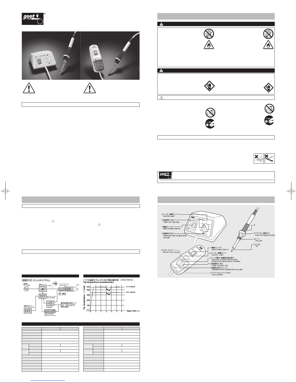
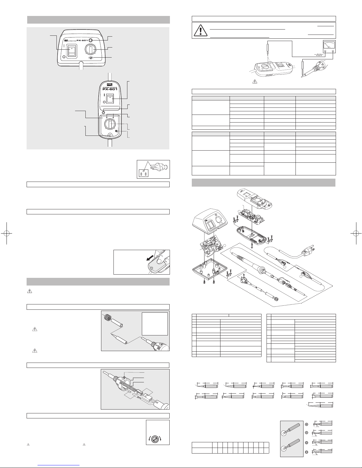
3.各部の名称と働き
NAME OF PARTS & DESCRIPTIONS
ステーション部
①電源スイッチ
主電源スイッチです。作業を中断する時、長 時間使用しない時
は必ず OFF にしてください。
②ヒーター通電ランプ
ヒーターが通電中に点灯します。こて先温度が設定温度に達す
ると点滅し(ON-OFF 制御)使用可能であることを知らせます。
③温度設定つまみ
こて先温度を設定します。
④温度校正用ボリューム
温度校正用ボリュームです。ヒーター、こて部を交換した際に
このボリュームで温度校正をおこなってください。
⑤リーク電流/絶縁抵抗測定用端子(PX-601 のみ)
リーク電流、絶縁抵抗 を測定する端子です。こて先とこの端子
間でリーク電流/絶縁抵抗を測定してください。
⑥スライドカバー(PX-601のみ)
温度設定ボリュームで温度設定後、容易に設定が変わらない様
に保護するカバーです。作業中はカバーをしたままご使用くだ
さい。
⑦スライドカバーロックねじ(PX-601 のみ)
スライドカバーが動かないようにロックするためのねじです。
こて部
⑧グリップラバー
⑨アダプター固定ねじ
ヒーター交換を行う際にはこのねじを緩めてアダプターを外し
てください。
⑩ナット
こて先交換の際にはこのナットを外して交換します。
⑪こて先
特殊コ
ーティングを施した専用こて先です。豊富な 替えこて先
を取り揃えています。(6. 分解図・交換部品参照)
Control Unit
①
Main power switch
Be sure to turn OFF when not in use.
②
Heater lamp
L ED l amp light s wh en t he heate r is ON. Whe n th e se t
temperature is reached, the lamp starts to flicker, signaling
that the soldering station is ready to use.
③
Temperature setting dial
Turn the dial to the desired temperature .
④
Temperature calibration knob
After replacing the tip and/or heater, temperature calibration
is required.
⑤
Measuring terminal (PX-601(AS))
For measuring leakage current and insulation resistance.
⑥
Protective cover (PX-601(AS))
P revent s any acc identa l te mperat ure a nd o ther setti ng
changes.
⑦
Lock screw (PX-601(AS))
Prevents the protective cover from accidentally opening.
Soldering Unit
⑧
Grip rubber
⑨
Adapter fixing screw
L oosen the fixin g scr ew an d rem ove the a dapte r whe n
replacing the heater.
⑩
Collar
Loosen the collar when replacing the tip.
⑪
Tip
Th e tip is co vered i n a special plating. Tips with various
shapes are available.
PX-601
PX-501
●温度設定
250〜450℃の間で温度 設定ができます。250℃で±10%、300℃〜
450℃設定で±5%程度の温度差が生じる場合があります。正確な温度を
設定する必要がある場合は、こて先温度計で温度調節を行ってください。
●リーク電流/絶縁抵抗測定端子付
リーク電流/絶縁抵抗の測定が容易にできる端子付。デリケートな
作業にも安心してご使用いただけます。
●保護カバー
温度調整つまみ、リーク電流/絶縁抵抗測定端子部にはロック機能
付の保護カバーを採用。つまみ、端子の保護と同時に確実な温度管
理作業が可能となります。(PAT.)
●クイックスタート
電源O N から設定温度まですばやい立ち上がりのクイックスタート
回路採用。(PAT.)
● Temperature setting range
The temp eratur e can be v ariabl y set fro m 250°C to 450°C .
Temperat ure d iffere nces may be o bserve d. (±10% at 250°C
temp eratu re s ettin g,±5% at 300°C 450 °Cset ting ) Use tip
therm ometer when the accurat e temper ature is requir ed.
● Leakage current / insulati on resistance measuring termi nal.
(PX-601(AS))
The PX-601 is equipped with a measuring terminal allowing easy
measurem ent of leak age current and insula tion resist ance.This
ensures precision components will not be damaged when soldering.
● Protective cover (PX-601(AS))
A p rot ec tiv e c ove r,s ecu red w ith a sc rew, p rev ent s a ny
accident al temperature an d other setting ch anges.(PAT.)
● Quick start
A quick he at up circu it (PAT.) increases the speed at which the
solderin g station reaches s et temperature s.
ブロックダイヤグラム / BLOCK DIAGRAM
TIP TEMPERATURE STABILITY
*この特性表はこて先の先端に熱電対をつけて測定し、作業は 5mm 角のランドへ連続しては
んだ付けし、測定したものです。(こて先/ PX-60RT-B)
* Thermo-couple fitted to the tip. Solder melted constantly on 5X5 mm PCB trace
layout. (Tip : PX-60RT-B)
2. 特長および特性・仕様
FEATURES / SPECIFICATIONS
PX-601(AS)
PX-501(AS)
仕 様/SPECIFICATIONS
●温度設定
250〜 450℃の間で温度設定ができます。250℃で±10%、300℃〜
450℃設定で±5%程度の温度差が生じる場合があります。正確な温度を
設定する必要がある場合は、こて先温度計で温度調節を行ってください。
●クイックスタート
電源O N から設定温度まですばやい立ち上がりのクイックスタート
回路採用。(PAT.)
● Temperature setting range
The temp eratur e can be v ariabl y set fro m 250°C to 450°C .
Temperat ure d iffere nces may be o bserve d. (±10% at 250°C
temp eratu re s ettin g,±5% at 300°C 450 °Cset ting ) Use tip
therm ometer when the accurat e temper ature is requir ed.
● Quick start
A quick heat up c ircuit (PAT.) increas es the spe ed at whic h the
solderin g station reaches s et temperature s.
Setat450℃
測定方法 5-4を必ずお読みください。
Please refer to 5-4
Setat350℃
GRIPRUBBER
グリップラバー
型 番 PX-601
(AS)
PX-501
(AS)
定格電圧 100V 50/60Hz
消費電力 85W
こて部電圧/電力 100V AC /80W
設定温度範囲
250~450˚C
絶縁抵抗(500V DC) 100MΩ 以上
サイズ
本体 W48:H31:D130(mm)W100:H57:D85(mm)
こて部 全長 195mm(コードアーマー除く)
重量
本体 75g(コード除く) 266g(コード除く)
こて部 41g(コード除く)
こて部〜制御部間コード長
1.2m(3 芯コード)
電源コード長 1.5m(3 芯コード・アースピンプラグ)
無負荷時温度リップル ± 5℃
リーク電圧 2mV 以下
アース抵抗 2Ω以下
温度制御方式 センサーフィードバック(ON-OFF 制御)
MODEL PX-6 01(AS) PX-501(AS)
Voltage 110, 220-240V AC
Power Consum ption 85W
Soldering Un it Voltage 110, 220-240V AC
Temp. Setting Ra nge 250-450 °C
Insulation R esistance Over 100MΩ
Dimensions
Control Un it
W48 : H31 : D130(mm) W100 : H57 : D85(mm)
Soldering Un it 195mm
Weight
Control Un it 75g (w/o cord) 266g (w/o cor d)
Soldering Un it 41g (w/o cord)
Control Unit t o Soldering Unit C ord Length
1.2m
Power Cord Le ngth 1.5m (3 core cord) / ground plu g
Ripple Temp. withou t Load ±5˚C
Leak Voltage Under 2mV
Ground Resis tance Under 2Ω
Temp. Control Sy stem Sensor feed ba ck (ON-OFF co ntrol)
The PX-501AS, PX-601AS are anti-static models. Be sure to properly
ground the soldering station using a grounded receptacle to prevent
elec trical shoc ks a nd an ti-sta tic. If it is not proper ly gr ounded
electrical shocks will occur.
As t he sol dering statio n uses condu ctive materia ls,
please be careful not t o touch any electr ical p ower
source or a serious injury will result.
●感電防止および静電対策の為に、電源プラグのアースピン
を必ずアース接地してください。アー ス接地をしない場合
は感電の危険があります。
●静電対 策の為、特殊な仕 様となっ ていま すの
でご注意 くださ い。特に 導電性 材料を使 用し
ています ので、電 源ライ ンとの 接触で事 故を
起こす場合がありますのでご注意ください。
300
350
400
450
CAL
250
プローブを測定端子穴
に交互に差し込み高い
方の値をとる。
1kΩ
リーク電流測 定時は
1kΩの抵抗を回路に
直列に接続します
Insert probe into both
terminals alternately to
establish which value is
higher.
Connect 1kΩresistor
(in series) for measuring
leakage current.
電源コードのプラグは 3 ピンプラグになっていますのでテ ー
ブルタップは3 ピンプラグ用を使用してください。尚、アース
は必ず接地してください。
5.保守と故障対策
MAINTENANCE AND TROUBLESHOOTING GUIDE
1)図 のようにリーク電流計(又は 絶縁抵抗計 )の2
本のプローブの内一つをこて先に接触させ、残り
を PX-601 の測定用端子の穴に差し込みどちら
か大きな値を測定します。
2)リーク電流測定時は回路に直列に 1k Ωの抵抗を
接続してください。( 電気用品 安全法に基 づく測
定)
1) Place one of the two probes in the leakage current meter
against the tip as shown in the illustration. Then insert
the other probe into the measuring terminal hole in the
PX-601 and measure the larger value at either side.
2) When measuring the leakage current, be sure to connect
a 1KΩ resistor with the circuit in series.
STEP 1. 温度設定つまみ③で希望温度に設定してください。
STEP 2. 電源スイッチ①を入れてください。ヒーター通電ラ
ンプ②が点灯し、ヒーターが加熱しはじめます。こて
先温度が設定 温度に達すると、ヒータ ー通電ランプ
が一定間隔で点滅し、ご使用可能になります。
STEP 1.
Set the tempe rature sett ing d ial t o th e des ired
temperature.
STEP 2.
Turn ON the main power switch. The heater lamp
lights and the heater starts to h eat up. When the
lamp starts to flicker, the soldering station is ready
to use.
4.ご使用方法
OPERATING PROCEDURES
6.分解図・交換部品
DISASSEMBLY ILLUSTRATION AND REPLACEMENT PARTS
STEP 1. スライドカバーロックねじ⑦をドライバーで緩めてく
ださい。
STEP 2. 図のようにスライドカバーを親指の腹で軽く押し下げ
ながら矢印の方向にスライドさせてください。
STEP 3. 温度設定つまみ③で希望温度に設定してください。
設定終了後はカバーをふたたび装着し、スライドカバ
ーロックねじ⑦を締めてください。
STEP 4. 電源スイッチ①を入れてください。ヒーター通電ラン
プ②が点灯し、ヒーターが加熱しはじめます。こて先
温度が設定温度に達すると、ヒーター通電ランプが一
定間隔で点滅し、ご使用可能になります。
PX-601 スライドカバーの外し方
Slide the protective cover
forward.
電源コードとご使用されるテーブルタップについて / Power Cord and Receptacle
4-1PX-501(AS) の使用方法
/ HOW TO OPERATE PX-501(AS)
4-2 PX-601(AS) の使用方法 / HOW TO OPERATE PX-601(AS)
The power cord plug is a ground pin
type. Plug it into a ground pin type
receptacle to properly ground it.
STEP 1.
Loosen the l ock screw.
STEP 2.
Slide the pr otective cover forw ard.
STEP 3.
Se t t he tem per atu re set tin g dia l t o t he des ire d
temperat ure. Slide the prote ctive cover back ward and
tig hten th e lo ck s cre w to pre vent any ac cide nta l
setting ch anges.
STEP 4.
Turn ON the main powe r sw itch . Th e he ater lamp
lights and the heat st arts to heat up. When th e lamp
starts to f licker, the solderin g station is ready to u se.
STEP 1. こて部のナットを時計と反対方向に回して取り外します。
STEP 2.ヒーターパイプ を抜いてこて先をヒーターから抜き取っ
てください。
STEP 3.こて先を交換したら逆の順序で組み立てます。
焼き付き防止のため、こて先は、時々ヒー ターから引き
抜いて内部の酸化物を取り除いてください。
STEP 1.
Loosen the collar and remove the heater barrel and
the tip.
STEP 2.
Replace the tip and assemble by reversing the
disassembly procedure.
アダプター固定ねじ
ADAPTER FIXING SCREW
アダプター
ADAPTER
ヒーター
HEATER
接続する
CONNECTOR
接続する
CONNECTOR
STEP 1.アダプター固定ねじをドライバーで緩めてください。
STEP 2.アダプターを回してこてから引き抜き、2 箇所のコネク
タを外してヒータを取り外します。
STEP 3.新しいヒーターと交換した後、逆の順序で組み立てます。
STEP 1.
Loosen the adapter fixing screw using a screw
driver.
STEP 2.
Slightly turn the adapter counterclockwise and
remove it. Disconnect the two connectors as shown
in the picture. Replace the heater and assemble by
reversing the disassembly procedure.
5-1こて先の交換方法 / TIP REPLACEMENT
5-2ヒーターの交換方法 / HEATER REPLACEMENT
5-3温度校正の方法
/
TEMPERATURE CALIBRATION (Tip thermometer is required.)
こて先やヒーターを交換する時は必ず電源スイッチを切り、電源コードをコンセントから抜いてください。
また、交換後は後述の温度校正を行ってください。
After replacing the tip and/or heater, be sure to calibrate the temperature. Never attempt to replace the tip and/or heater
while it is hot or serious burns will result.
こて先の種類を変えた場合およびヒーター交換を行
った場合は高 信頼のは んだ付け作 業を行うため 温
度 校 正 を 行っ て くだ さ い。温 度 設 定 つ ま み を
350℃に設定し、こて先温度を測りながら温度校正
用ボリュームを回して温度調整を行ってください。
500℃以上に設定す ると本器が破損す
ることがありますのでご注意ください。
Aft er r eplac ing the tip and/ or h eate r, tem pera ture
calibration is required. Set the temperature setting dial
at 350°C. While meas uring the tip temperature, adjust
the temperature by turning the calibration volume using
a standard screwdriver (-).
Do not a ttemp t to set the temper ature
over 500
˚C
or the station may be damaged.
高温Hi.
低温Lo.
温度校正用ボリューム
5-4
リーク電流
/
絶縁抵抗の測定 (PX-601)
/
LEAKAGE CURRENT / INSULATION RESISTANCE VALUE MEASUREMENT (PX-601(AS))
5-5故障と原因対策 / TROUBLESHOOTING GUIDE
TEMP. CALIBRATION
VOLUME
リーク電流/絶縁抵抗の測定は、アースを接地しない状態でおこなってください。また、アースライン
を接地したままリーク電流を測定すると、電流計が破損します。
When measuring the leakage current and insulation resistance, do not ground. If the leakage current
is measured, the current meter will be damaged.
Regularly remove the oxidized particles in the tip to
prevent the tip from sticking to the heater.
交換用こて先(オプション) / Replacementtips
交換部品
/ Replacementparts
こて先をヒ ーターから 取り外し
た際、こて先内のパイプ金具がヒ
ータに付着して いる場合 があり
ます。必ずヒータからこて先パイ
プを取り除いてください。
The stainless sleeve inside of the
tip may h appen to stick to the
heater when pulling out the t ip
fro m th e hea te r. Be s ure t o
remove the stainless sleeve.
*3 ピン用のコンセントが無い場合は 3ピン -2 ピン変換プラグ
P-10(別売)をご使用ください。
*コントロール部は付属のマジックテープで固定できます。
電流計のプローブを2 本同時に測定端子に差し込まないで下さい。
Do not insert the probes into the two measuring terminals at the
same time.
工場出荷時の温度設定は標準こて先(PX- 60RT-B)を基準にしてあります。他のタイプ
のこて先を使用した場合、形状・重量 等の違いにより設定温 度との温度差が 生じます。
5-3 の「温度設定の方法」に従って温度校正を行ってください。温度 校正を行わずに使
用される場合は下記の表を参考にしてください。
The te mperature setting is adju sted for the standard tip (PX -60RT-B)
when shipped. Whe n using other tip s, temperatu re offset may occur
due to the different shapes, weights etc. If offset occurs, calibrate (refer
to 5-3 TEMPE RATURE CALI BRATION ). T he ch art below giv es a n
approximation of the temperature offset. Please use it as a reference.
Round Solder-plated type
Standard type
45
45
45
45
1
26
φ 6.5
15
φ2.1
26
φ 6.5
17
φ3
26
φ 6.5
17
φ4
26
φ 6.5
17
PX-60RT-1CR
PX-60RT-2CR
PX-60RT-3CR
PX-60RT-4CR
標準タイプ
全周はんだメッキタイプ
全周はんだメッキこて先/
Round solder-plated tips
※別途こて先温度計が必要です。
250
300 350
400
450
CAL
+
-
①電源スイッチ
MAIN POWER SWITCH HEATER LAMP
TEMP. SETTING DIAL
②ヒーター通電ランプ
③温度設定つまみ
TEMPERATURE CALIBRATION
VOLUME
④温度校正用ボリューム
250
300 350
400
450
CAL.
+
①電源スイッチ
MAIN POWER SWITCH
HEATER LAMP
TEMP SETTING DIAL
LOCK SCREW
②ヒーター通電ランプ
LEAKAGE CURRENT /
INSULATION RESISTANCE
MEASURING TERMINAL
⑤リーク電流/絶縁抵抗測定端子
③温度設定つまみ
TEMPERATURE
CALIBRATION VOLUME
④温度校正用ボリューム
PROTECTIVE COVER
⑥スライドカバー
⑦スライドカバーロックねじ
CAL.
+
-
A
A
B
B
B
⑤
①
③
②
⑥
④
⑩
⑪
⑨
⑪
⑧
⑦
A
PX-60RT-SB
26
R0.2
φ6.5
1
φ1.6
26
15
φ5
PX-60RT-5K
17
PX-60RT-1CPX-60RT-B
26
R0.5
φ6.5
17
Standard
PX-60RT-LB
26
R0.2
φ6.5
25
PX-60RT-1.6D
26
φ6.5
17
26
φ6.5
15
φ2.1
PX-60RT-2C
26
φ6.5
17
φ3
PX-60RT-3C
26
φ6.5
17
φ4
PX-60RT-4C
26
φ6.5
φ6.5
17
φ2.4
PX-60RT-2.4D
26
φ6.5
17
φ3.2
PX-60RT-3.2D
26
φ6.5
17
症 状 原 因 対 策 備 考/参 照
ヒーター通電ランプが点灯しない。
ヒーターが加熱しない
電源コードが外れている 接続してください。
ヒューズが切れている ヒューズを交換 分解図の項を参照
プリント基板が故障 販売店に連絡
電源コードが切れている 販売店に連絡
ヒーター通電ランプが点灯した
まま加熱しない。
ヒーターの故障 ヒーターを交換する ヒーター交換を参照
こて部のコードが切れている
こて部の交換
プリント基板が故障 販売店に連絡
ヒューズを交換しても動作しない
プリント基板が故障 販売店に連絡
Trouble Check Countermeasure Remarks
The heater lamp does not light,
and the heater does not heat
up.
Is the power cord plugged in? Plug it in properly.
Is the fuse blown? Replace it. Refer to 6. DISASSEMBLY ILLUSTRATION
The PCB may be damaged.
Contact the dealer or distributor
you purchased it from for repair.
Is the power cord damaged?
The heater does not heat up
although the lamp lights.
Is the heater damaged? Replace the heater. Refer to 5-2 HEATER REPLACEMENT
Is the cord of the soldering unit
damaged?
Replace the soldering unit.
The PCB may be damaged.
Contact the dealer or distributor
you purchased it from for repair.
The heater does not heat up
after replacing the fuse.
The PCB may be damaged.
こ て先
TIP
HEATER
ヒ ータ ー
ヒ ータ ーパイ プ
HEATER BARREL
ナッ ト
COLLAR
No.
PartsName
①
Tip
② Heater
PX-60H 100–110V
PX-60H 220–240V
③ Heater Barrel PX-60HP
④ Collar TQ-77NUT
⑤ Adapter
PX-601 Adapter
PX-601AS Adapter
⑥
Grip Rubber
⑦
Soldering Unit PX-60G
110V
PX-60G
220-240V
Soldering Unit AS
PX-60GAS
110V
PX-60G AS
220-240V
⑧ PX-501PCB ASSY.
PX-501
PCB 100-110V
PX-501PCB 220-240V
⑨ PX-601PCB ASSY.
PX-601
PCB 100-110V
PX-601PCB 220-240V
⑩ AC power cord
⑪ Fuse
250V 1A 220-240V
250V 2A 100-110V
No.
部品名 仕様/型番
①
こて先
② ヒーター PX-60H
③ ヒーターパイプ PX-60HP
④ ナット TQ-77NUT
⑤ アダプター
PX-601 アダプター
PX-601AS アダプター
⑥ グリップカバー
⑦
こて部 PX-60G
こて部 AS用 PX-60GAS
⑧ PX-501 基板部 PX-501PCB
⑨ PX-601 基板部 PX-601PCB
⑩ 電源コード
⑪ 電流ヒューズ 250V 2A
こて先の種類/
Tip type
B SB 1C 2C 3C 4C 1.6D 2.4D 3.2D 5K LB
温度差(℃)/
Temperature Offset
0(Cal)
-20 -5 -10 -15 0 0 -5 -5 0 -20
これら以外のこて先形状につきましては弊社総合カタログまたはWeb サイトにてご確認ください。
Please see our catalog for other shape.
 Loading...