

Page 1

SketchUp User's Guide
©Google Inc. 2006 Page 1 6/16/2006
Page 2

Page 3

Table Of Contents
Welcome to SketchUp (Microsoft Windows)....................................................................................1
Using the Online User's Guide.................................................................................................2
Technical Support.....................................................................................................................6
Learning SketchUp...................................................................................................................7
Concepts............................................................................................................................................. 9
Designing in SketchUp...........................................................................................................10
Drawing Quickly......................................................................................................................15
Viewing Models in 3 Dimensions...........................................................................................22
Adding Detail to Your Models................................................................................................25
Presenting Your Models.........................................................................................................32
Modeling Terrain and Organic Shapes.................................................................................35
The SketchUp User Interface..........................................................................................................39
Introduction to the SketchUp Interface..................................................................................40
File Menu.................................................................................................................................44
Edit Menu................................................................................................................................48
View Menu...............................................................................................................................51
Camera Menu.........................................................................................................................53
Draw Menu...................................................................................................................... ........55
Tools Menu..............................................................................................................................56
Window Menu.........................................................................................................................59
Google Menu ..........................................................................................................................61
Help Menu...............................................................................................................................62
Toolbars...................................................................................................................................65
Context Menus........................................................................................................................ 68
Dialog Boxes...........................................................................................................................69
Drawing Axes..........................................................................................................................71
Inference..................................................................................................................................73
Principal Tools ..................................................................................................................................77
Select Tool...............................................................................................................................78
Eraser Tool..............................................................................................................................82
Paint Bucket Tool....................................................................................................................83
Drawing Tools...................................................................................................................................87
Line Tool..................................................................................................................................88
Arc Tool ...................................................................................................................................92
Freehand Tool.........................................................................................................................94
©Google Inc. 2006 Page iii 6/16/2006
Page 4

SketchUp User's Guide
Rectangle Tool........................................................................................................................96
Circle Tool ...............................................................................................................................98
Polygon Tool.........................................................................................................................100
Modification Tools...........................................................................................................................103
Move Tool..............................................................................................................................104
Rotate Tool............................................................................................................................110
Scale Tool..............................................................................................................................115
Push/Pull Tool.......................................................................................................................119
Follow Me Tool......................................................................................................................123
Offset Tool.............................................................................................................................127
Intersect With Model Tool.....................................................................................................130
Position Texture Tool............................................................................................................132
Construction Tools..........................................................................................................................139
Tape Measure Tool..............................................................................................................140
Protractor Tool ......................................................................................................................143
Axes Tool...............................................................................................................................147
Dimensions Tool...................................................................................................................148
Text Tool................................................................................................................................150
Section Plane Tool................................................................................................................153
Camera Tools.................................................................................................................................155
Previous.................................................................................................................................156
Standard Views.....................................................................................................................157
Orbit Tool...............................................................................................................................158
Pan Tool................................................................................................................................159
Zoom Tool.............................................................................................................................160
Zoom Window Tool ..............................................................................................................161
Zoom Extents Tool................................................................................................................162
Walkthrough Tools .........................................................................................................................163
Position Camera Tool...........................................................................................................164
Walk Tool...............................................................................................................................166
Look Around Tool .................................................................................................................167
Sandbox Tools................................................................................................................................169
Sandbox From Contours Tool .............................................................................................170
Sandbox From Scratch Tool................................................................................................171
Smoove Tool.........................................................................................................................173
Stamp Tool............................................................................................................................175
Toggle Terrain Tool..............................................................................................................176
©Google Inc. 2006 Page iv 6/16/2006
Page 5

Table Of Contents
Add Detail Tool......................................................................................................................178
Flip Edge Tool.......................................................................................................................181
Google Toolbar...............................................................................................................................183
Get Current View Button......................................................................................................185
Toggle Terrain Button...........................................................................................................186
Place Model Button ..............................................................................................................187
Share Model Button............................................................................................................. .188
Get Models Button................................................................................................................189
Model Settings and Managers.......................................................................................................191
Model Info Dialog Box..........................................................................................................192
Entity Info Dialog Box...........................................................................................................202
Material Browser...................................................................................................................203
Material Editor.......................................................................................................................207
Component Browser.............................................................................................................210
Layer Manager......................................................................................................................213
Page Manager......................................................................................................................215
Display Settings Dialog Box.................................................................................................218
Shadow Settings Dialog Box...............................................................................................225
Soften Edges Dialog Box.....................................................................................................227
Outliner..................................................................................................................................229
Instructor................................................................................................................................233
Application Preferences Dialog Box....................................................................................234
Entities.............................................................................................................................................241
Arc Entities ............................................................................................................................242
Circle Entities.........................................................................................................................244
Component Entities..............................................................................................................246
Construction Lines Entities...................................................................................................255
Construction Point Entities...................................................................................................256
Curve Entities........................................................................................................................257
Dimension Entities................................................................................................................258
Face Entities..........................................................................................................................259
3D Polyline Entities...............................................................................................................260
Group Entities .......................................................................................................................261
Image Entities .......................................................................................................................264
Line Entities...........................................................................................................................265
Polygon Entities....................................................................................................................266
Section Plane Entities...........................................................................................................268
©Google Inc. 2006 Page v 6/16/2006
Page 6

SketchUp User's Guide
Surface Entities.....................................................................................................................269
Text Entities...........................................................................................................................272
Context Menu Items .............................................................................................................273
Entity Info...............................................................................................................................279
Input and Output.............................................................................................................................283
2D Graphic Export................................................................................................................284
2D Graphic (DWG/DXF) Export..........................................................................................285
2D Graphic (PDF/EPS) Export............................................................................................288
2D Graphic (Epix) Export.....................................................................................................291
3D Model (DWG/DXF) Export.............................................................................................293
3D Model (3DS) Export........................................................................................................294
3D Model (VRML) Export.....................................................................................................298
3D Model (OBJ) Export........................................................................................................300
3D Model (FBX) Export........................................................................................................302
3D Model (XSI) Export .........................................................................................................303
3D Model (KMZ) Export.......................................................................................................304
Section Slice Export..............................................................................................................305
Animation Export...................................................................................................................307
2D Graphic Import................................................................................................................310
3D Model (DWG/DXF) Import..............................................................................................311
3D Model (3DS) Import........................................................................................................313
3D Model (DEM) Import.......................................................................................................314
3D Model (KMZ/KML) Import...............................................................................................316
3D Model (SHP) Import........................................................................................................317
Pages and TourGuide™................................................................................................................319
Printing ............................................................................................................................................320
Technical Info..................................................................................................................................325
Raster File Formats..............................................................................................................326
2D Vector File Formats ........................................................................................................328
SketchUp and OpenGL........................................................................................................330
Codec Lists............................................................................................................................332
Bug Splat...............................................................................................................................333
SketchUp Ruby API and Console.......................................................................................334
Color Pickers.........................................................................................................................335
Uninstalling SketchUp..........................................................................................................337
Common Tasks..............................................................................................................................339
Activating the Sandbox Tools..............................................................................................340
©Google Inc. 2006 Page vi 6/16/2006
Page 7

Table Of Contents
Adding a Background to Your Model..................................................................................341
Copying Geometry................................................................................................................342
Creating Models to Scale.....................................................................................................343
Creating and Using Keyboard Shortcuts ............................................................................344
Drawing Accurate Angled Lines ..........................................................................................345
Flipping or Mirroring Geometry............................................................................................346
Reorienting Materials............................................................................................................349
Using SketchUp With Google Earth....................................................................................350
Glossary..........................................................................................................................................351
Index ................................................................................................................................................357
©Google Inc. 2006 Page vii 6/16/2006
Page 8

Page 9

Welcome to SketchUp (Microsof t Windows)
Developed for the conceptual stages of design, SketchUp is powerful yet easy-to-learn 3D
software. We think of it as the pencil of digital design. This award-winning software combines a
simple, yet robust tool-set that streamlines and simplifies 3D design inside your computer.
SketchUp is being used by anyone with the desire to Dream, Design and Communicate in 3D!
From the entire SketchUp team, thank you for trying SketchUp, and welcome to the SketchUp
user community.
SketchUp Versions
SketchUp is available in personal and professional versions. Google SketchUp (free) is a 3D
design tool for personal use and is available for free on sketchup.google.com.
SketchUp Pro 5 is approved for commercial use and is available to purchase on
sketchup.google.com. You need SketchUp Pro 5 if you want to:
• Export models in 3DS, DWG, DXF, OBJ, XSI, VRML, and FBX file formats
• Export animations and walkthroughs as MOV or AVI files
• Access the organic modeling (Sandbox) tools
• Print and export raster images at higher-than-screen resolution
• Receive free email technical support for two years after purchase
• Use the software for commercial purposes (the free version is approved for personal use
only)
Google SketchUp (free) and SketchUp Pro 5 Documentation
This documentation represents all of the functionality in both Google SketchUp (free) and
SketchUp Pro 5. Functionality that is specific to SketchUp Pro 5 is identified with the pro icon
(
) in this documentation.
Using this Guide
Familiarity with computer basics is all you need to use SketchUp. Continue with the Learning
SketchUp section of this guide for assistance with learning SketchUp. Or, read the What 's New
in This Release section of this guide to become familiar with SketchUp's new features.
©Google Inc. 2006 Page 1 6/16/2006
Page 10

SketchUp User's Guide
Using the Online User's Guide
The SketchUp Online User's Guide is a Web-based help system designe d to introduce you to
the SketchUp concepts and features. Refer to this user's guide to find explanations of each
SketchUp feature or to learn how to perform common tasks using SketchUp tools. Select the
SketchUp Help menu item from SketchUp's Help menu to access SketchUp Online User's
Guide.
The online user's guide contains a toolbar on top, navigation panel (below the toolbar on the
left), and content panel containing the actual user's guide content (below the toolbar on the
right).
The Online User's Guide Toolbar
The SketchUp Online User's Guide's toolbar contains four option s for finding the information.
These options are: The Contents button, the Index button, the Search button, and the Search
field.
The Contents Button
The Online User's Guide is organized into topics. Topics can be combined with rel ated topics
within chapters or can exist outside of a chapter. Additionally, topics can have subtopics. Click
on the Contents button in the Online User's Guide Toolbar to view all of the chapters in the
user's guide. Click on the chapter icon (a small book) to view topics within that chapter. The
following image shows all of the chapters in the SketchUp Online User's Guide. This image also
shows all of the topics in the Principal Tools chapter.
Click on a topic to see the user's guide entry for that topic. Topics can contain multiple
subtopics. For example, the Eraser Tool topic contains the Erasing Entities, Hiding Edges, and
©Google Inc. 2006 Page 2 6/16/2006
Page 11

Welcome to SketchUp
Soften Edges subtopics. The following image shows the Erasing Entities subtopic with in the
Eraser Tool topic.
The Index Button
Click on the Index button to display a keywords search field and index entries in the online
user's guide. Click on an index entry in the index list to navigate to that topic or subtopic.
An index entry can be used for more than one topic or subtopics. A sublist is displayed when an
index entry is linked to more than one topics or subtopic. Select an item from this sublist to jump
©Google Inc. 2006 Page 3 6/16/2006
Page 12

SketchUp User's Guide
to a topic or subtopic. The following image shows that the Copy index entry contains related
subtopics in the Edit Menu topic and in the Move Tool topic.
The Search Button
Click on the Search button at the top of the online SketchUp Users Guide to search the entire
user's guide for keywords and return the topics where those keywords exist. The following
image shows the topics resulting from looking up the word "Copy." Notice that only topics are
returned, not subtopics.
Conventions
The user's guide uses these special symbols and conventions:
©Google Inc. 2006 Page 4 6/16/2006
Tip - Use the Search button or Search only when you want to find all occurrences of a
specific word or phrase throughout the entire user's guide. Use the Index button to find
specific index entries and their associated topics.
Note - The Note icon is used to indicate additional detail for a feature of SketchUp.
Video - The projector icon is used to identify a Video Tutorial that compliments the text by
explaining how to use a feature of SketchUp.
Page 13

Caution - The Caution icon is used to identify issues that might cause you problems.
Tip - The Tip icon is used to identify a tip to help you optimize the way you use SketchUp.
Menu > Menu Item - Used to identify a location for a specific menu item.
italics - Used to identify a term that is defined in the glossary.
<a_value> - Used to identify a value you must supply.
Welcome to SketchUp
©Google Inc. 2006 Page 5 6/16/2006
Page 14

SketchUp User's Guide
Technical Support
Google SketchUp (Free) and SketchUp Pro users have different levels of technical support.
Review the following technical support explanation for the your product.
SketchUp Free
SketchUp Free is a self-supporting product. There are several options available to find answers
to SketchUp your issues:
• Use the online user's guide index to find a topic.
• Search the knowledge base to find a topic.
• Post a question in our user forum.
Visit the SketchUp Help Center by clicking on the Help Center menu item in the Help Menu
(Help > Help Center...). You must be connected to the Internet to access the user forums.
SketchUp Pro
In addition to the self-supporting options for SketchUp Free, SketchUp Pro users can request
installation and configuration help using email through the SketchUp Help Center (your serial
number will be required).
Please include the following with your email:
• A copy of the SketchUp file you are creating
• A list of your computer system's resources (CPU type, RAM, video card details, and the
exact release of your operating system, such as Windows XP Professional with Service
Pack 2)
• A detailed description of your question or issue
©Google Inc. 2006 Page 6 6/16/2006
Page 15

Learning SketchUp
As with any software tool, there is a minimum level of learning you must do to attain proficiency
with SketchUp. The following information can help you learn how to use SketchUp.
Welcome to SketchUp
Video Tutorials
Google has created several video tutorials to facilitate learning of the SketchUp tools and
drawing procedures. View these tutorials through the View Tutorials menu item in the Help
Menu (Help > View Tutorials). You must be connected to the Internet to access these tutorials.
These video tutorials will also play directly from the CD-ROM if you have a SketchUp CD-ROM
inserted into your drive. If the CD-ROM is not in your drive, your computer will attempt to access
streaming versions of the tutorials from the SketchUp web site
online tutorials from the Web site to your hard drive to ensure they play smoothly.
Self-Paced Tutorials
Google has also created several self-paced tutorials to help you learn SketchUp. Acce ss these
tutorials through the Self-Paced Tutorials menu item in the Help Menu (Help > Self-Paced
Tutorials). You must be connected to the Internet to access these tutorials.
Online User's Guide
This online user's guide contains a Concepts section for users who are new to working in three
dimensions or new to SketchUp. This section is meant to be read sequentially before using
SketchUp for the first time. You must be connected to the Internet to access this guide.
Menus
Most SketchUp commands are accessible using both tool buttons an d drop-down menus.
Examine SketchUp's menus to become familiar with the breadth of features.
. You can also download the
Quick Reference Card
The SketchUp Quick Reference Card, available in the SketchUp Help Menu and on the
sketchup.google.com, contains a list of all of toolbar tools and their modifier keys. Examine the
©Google Inc. 2006 Page 7 6/16/2006
Page 16

SketchUp User's Guide
SketchUp Quick Reference card to become familiar with using SketchUp's tools. View the quick
reference card the Quick Reference menu item in the Help Menu (Help > Quick Refe rence).
The Status Bar
The Status Bar, located at the bottom of the SketchUp Drawing Area, displays tips for the active
tool, including special functions accessible using keyboard shortcuts. Watch the status bar while
you are working in SketchUp to discover advanced capabilities of each of the SketchUp tools.
User Forum
The SketchUp forums are a great way to contact others in the SketchUp user community.
These forums provide a unique environment for you to obtain help, suggest new features, offer
advice, and share your models. Visit the SketchUp user forums by clicking on the SketchUp
Community... menu item in the Help Menu (Help > SketchUp Community...). You must be
connected to the Internet to access the user forums.
SketchUp Training
Google provides training courses for users who want extra assistance with SketchUp from the
experts at Google. Visit http://www.sketchup.com/training to see a list of training courses
available in your area.
©Google Inc. 2006 Page 8 6/16/2006
Page 17

Concepts
This section of the user's guide covers the numerous 3D desi gn and SketchUp concepts found
within the product and in the user community. This section was primarily written for users who
are new to 3D modeling or SketchUp.
Note - This section does not cover how to do something in SketchUp, but covers
important concepts necessary to model in 3D.
This section is organized into the following topics:
• Designing in Sketchup - Introduces you to the basic concepts behind drawing accu rately in
SketchUp.
• Drawing Quickly - Introduces you to SketchUp tools and concepts necessary to draw
quickly.
• Viewing Models in 3D - Presents the concept of the camera and manipulation of a model in
3D space.
• Adding Detail to Your Models - Introduces you to mechanisms to quickly add realism to
your SketchUp models.
• Presenting Your Models - Presents concepts related to the presentation of your models to
clients.
• Modeling Terrain and Organic Shapes - Presents concepts related to working with me sh
tools to create both terrain and organic shapes.
©Google Inc. 2006 Page 9 6/16/2006
Page 18

SketchUp User's Guide
Designing in SketchUp
SketchUp models are fundamentally created by joining lines as the edges of the model. Faces
are automatically created when any three or more lines or edges are in the same plane (an
infinite flat 2D space), or coplanar, and form a closed loop. These edge and face combinations
are combined to create 3D models. The following image shows three unconne cted coplanar
lines. These lines were drawn with the Line Tool
The following image shows four connected coplanar lines and the subsequently create d flat, 2
dimensional, face.
(this tool looks like a pencil).
Note - Everything you draw in SketchUp is generically referred to as geometry.
To create a 3D model, simply draw up or down in the blue direction (parallel to the blue axes).
The coordinate system (axes) is covered later in this section. The following image shows the
first line created in 3D space.
As you continue to draw lines, following the colored axes, faces are created. The following
image shows three faces created simply by drawing lines parallel to the three axe s directions
(red, green, and blue).
©Google Inc. 2006 Page 10 6/16/2006
Page 19

Concepts
There is one line left to draw to finish a 3 dimensional box. Notice that when this one line is
drawn in, two faces are created (the top and front faces).
You can do a lot in SketchUp simply by drawing lines to form faces using the Line Tool. And,
you can draw lines starting anywhere (on another line, on a face, at a point, and so on). Can
you recognize the previous 3D box within the model of the following house?
©Google Inc. 2006 Page 11 6/16/2006
Page 20

SketchUp User's Guide
Look around the room you are in. Notice how everything you look at has faces. Some faces
might be rounded, some might be flat. Additionally, everything has edges that bound the face,
such as the edge of a shelf in a bookshelf.
Note - SketchUp is not the same as Computer Assisted Design or CAD. CAD applications
are designed specifically for representing concrete information, while SketchUp is for
exploration and design of concepts and ideas (though yo u are not prohibited from
designing models that are as concrete or accurate as those designed in CAD).
SketchUp files can be imported into several different CAD applications for further
processing and several different CAD files can be imported into SketchUp to qui ckly
create 3D models.
Introduction to Entities
As mentioned previously, lines are combined to create faces in SketchUp. Lines (also called
edges) and faces, are just two of the many building blocks (called entities) used for creating
models in SketchUp. A full list of SketchUp entities follows.
Name Notes
Line Line s in SketchUp are straight. Lines, also referred to as edge s,
Face Faces are created automatically when three or more coplanar
Circle Circle, arcs, and curves are comprised of several lines or
Arc
Polygon
Curve
are the most basic building block for all SketchUp models.
edges form a closed loop. Faces have a front side and a back
side. SketchUp attempts to put the front side of all faces on the
outside (facing out) of all of your models, though sometime you
might have to tell SketchUp the direction for your faces.
edges.
3D Polyline
Group Group entities are used to combine two or more entities in your
©Google Inc. 2006 Page 12 6/16/2006
Page 21

model for quick operations such as a copy.
Component Component entities are like groups but can be reused in all of
your SketchUp models. Components are just SketchUp models
used within other SketchUp models.
Concepts
Construction
Line
Dimension A notation indicating length of an edge or a radius.
Surface Surface entities are the result of combining a number of faces to
Section
Plane
Image An imported raster, or pixel-based, image.
Text Text can be unattached (floating) or attached to a specific entity
A Construction Line entity is a temporary line used as a drawing
guide.
give the impression of smoothness.
using a leader line.
The SketchUp Coordinate Systems
SketchUp uses a 3D coordinate system whereby points in space are identified by position along
three drawing axes
SketchUp, plus or minus X is represented by solid red and dotted red lines respectively; plus or
minus Y are represented by a solid green and dotted green axis lines respectively; plus or
minus Z (above and below the ground plane) are represented by solid blue and d otted blue
lines respectively. The plane where the red and green axes lines lie is called the ground plane.
Finally, the term origin, is used to define the place where all of axes lines start or originate.
: plus or minus X, Y, and Z (above ground/below ground) values. In
The following image shows the drawing axes in SketchUp (the lines have been thicke ned to
make the axes easier to read). The black circle represents the origin.
Understanding SketchUp’s coordinate system is important because S ketchUp’s inference
engine (explained next) provides you help with drawing accurately.
©Google Inc. 2006 Page 13 6/16/2006
Page 22

SketchUp User's Guide
Following the Inference Engine
SketchUp has an invisible inference engine to help you draw accurate and realistic models. The
inference engine locates or infers points from other points in your model, such as the center of a
circle, the midpoint of a line, a line that is perpendicular to the ground plane, a point on a face, a
point on an edge, and so on.
SketchUp notifies you of these points by using both color indicators and tool tips, which are onscreen messages indicating the location of the cursor as you draw an entity. For example,
SketchUp displays the string “On Face" when the cursor is touching a face. The following image
contains five common inference tool tips.
Additional information on the inference engine
section of this guide.
The first step to drawing in SketchUp is to learn how to draw accurately by following the cues of
the inference engine. Simply select the Line Tool (it looks like a pencil in the toolbar) and start
drawing. Pay attention to the on-screen tool tips from the inference engine as you draw. Most
everything you will create in SketchUp can be created by inference using the Line Tool.
, including inference types, is in the User Interface
You can move on to learning how to draw quickly after you master using the inference engine.
= Functionality only available in SketchUp Pro
©Google Inc. 2006 Page 14 6/16/2006
Page 23

Drawing Quickly
As mentioned in the Design in SketchUp topic, you can use the Line Tool and the inference
engine, to draw just about anything in SketchUp. It is recommended that you use the Line Tool
and inference engine to create your initial models.
Tip - Learn to draw accurately before you learn to draw quickly and you will m aster
SketchUp in a shorter amount of time.
SketchUp implements several concepts which you will use to help you draw quickly. These are
dividing and healing, pushing and pulling, sticky geometry, autofold, and intersections.
Dividing and Healing Geometry
Some tools speed up design dramatically by allowing you to perform modifications on existing
geometry. For example, the Line Tool allows you to split faces and edges to create additional
independent faces and edges. Simply divide the face or edge with another edge. This con cept
is similar to cutting a piece of paper in half and having two separate remaining pieces. The
following image shows how two faces are created when dividing the face with a line. No tice the
image on the left has one solid top face, while the image on the right has two independent faces
when split with a line. Note that the dividing line does not cut through the model from top to
bottom, but just cuts the top face in half.
Concepts
The following image shows how the edges at each end of the face have been split to create
additional edges. Note four edges bounding the face in the left image, while four edges
bounding each of two faces in the image on the right (the middle edge being common to both
top faces).
©Google Inc. 2006 Page 15 6/16/2006
Page 24

SketchUp User's Guide
If you remove the line that shared by the two faces in the image on the right, the two faces will
be glued back together or healed back into one face. It is common in SketchUp to perform
these dividing and healing operations to your model.
Pushing and Pulling
The Push/Pull Tool allows you to take any non-curved face in SketchUp and push it away or
pull it toward a starting point (these operations are also referred to as extrusions). Pushing is the
process of reshaping a portion of your model by shrinking the portion away from its starting
point and along a single axis. The following image shows the right-most face of the split face
(shown earlier) pushed down toward the ground plane.
In the previous image, there are eight faces that can be pushed, can you find them (some are
hidden out of view)?
Pulling is the process of expanding a portion of your model away from the starting point along a
single axis. The following image shows the same face having been pulled up toward the sky.
Any face in SketchUp can be pushed and pulled (with some minor limitations).
©Google Inc. 2006 Page 16 6/16/2006
Page 25

In both of the images, the left side of the cube remained the same size, while the right side was
pushed and pulled (shrunk and expanded) independently. The Push/Pull Tool is one of the
most commonly used tools in SketchUp to add the sense of volume to your model.
Manipulating Connected Faces
Geometry in SketchUp is sticky meaning that it can be manipulated (skewed, distorted, or
folded) by selecting an edge or face and moving the edge or face with the Move Tool
all entities attached or "stuck" to the edge or face to move too). Following are three examples of
sticky geometry in SketchUp:
Concepts
(causing
1. The following image shows a line dividing the top face of a box being moved up with a
Move Tool. The faces that were connected to the middle line followed the line as it was
moved to create a roof-like effect.
2. The following image shows the left-most top face being moved down in the blue dire ction.
This action causes the left-most top face to angle to create a slant on one side.
©Google Inc. 2006 Page 17 6/16/2006
Page 26

SketchUp User's Guide
3. Finally, the following image shows the left-most top-edge being moved to the left. The
model is skewed into a trapazoid-like shape.
Be sure to use the Move Tool to grab and move edges and faces while you begin to experiment
with modeling in SketchUp.
Autofold
Faces must remain planar at all times in SketchUp. Therefore, SketchUp will Autofold, or score,
faces as necessary to accommodate any operation that will result in warped faces.
In the left-most image above, a six-sided polygon volume's top face (created with the Polygon
Tool followed by the Push/Pull Tool) was rotated using Rotate Tool. Because of SketchUp's
sticky nature, the sides of the shape, which share common edges with the top face, twisted and
folded with the rotate operation (right-most image).
Tip - Experimentation and play is highly important in learning how to draw in Sketch Up!
Learn how to draw accurately first, then learn how to draw quickly using the concepts in
this portion of the user's guide.
©Google Inc. 2006 Page 18 6/16/2006
Page 27

What you are not seeing is that SketchUp has created hidden geometry when performing this
Autofold operation. The following image shows the 3 dimensional shape with the hidden
geometry shown (dotted lines). Notice that each twisted faces are actually comprised of two
triangular faces.
Intersections (Boolean Operations)
SketchUp allows you to easily create complex geometry by intersecting two geometrical forms,
such as a box and a tube, creating new edges where the elements intersect, merging the
geometry, and subtracting parts of the combined geometry.
Concepts
In the left-most image above, a cylinder shape was moved into a cube shape. Notice, that no
lines appear where the two shapes intersect, indicating that the shapes have not truly merged.
A special tool, called the Intersect with Model Tool
middle image), merging the two shapes together to form one new shape. Finally, the cylinder
shape is deleted (using the eraser tool on the cylinder's edges) a nd because the intersection
lines were created, the resulting curved face is left within the cube creating a new complex
geometrical shape (right image).
SketchUp Tools
Most entities in SketchUp, including arcs and circles, are actually just a combination of small
lines or edges. Thankfully, you do not have to use only the Line Tool to sketch your models.
©Google Inc. 2006 Page 19 6/16/2006
, is used to create intersection lines (the
Page 28

SketchUp User's Guide
Instead, SketchUp provides many other tools to help you draw quickly. Some of these tools are
for creating common entities such as a circle, arc, polygon, or freehand line. Other tools allow
you to quickly draw complex models by modifying your models (splitting, skewing, and even
merging geometry together).
Tools in SketchUp are divided into five categories: principal tools (tools that are used a lot to
select and modify geometry), drawing tools (tools used to create geometry), modification tools
(tools used to modify existing geometry), construction tools (tools used to create construction
lines or points, and document your model), camera tools (tools used to view geometry;
discussed later), and walkthrough tools (tools to explore your model). The following table lists all
of the Drawing and Modification tools:
Tool Type Notes
Line Drawing Can be used to create, intersect, or divide
a face or other line (edge)
Arc Drawing Can be used to create, intersect, or divide
a face or other line (edge)
Freehand Drawing Can be used to create, intersect, or divide
a face or other line (edge)
Rectangle Drawing Can be used to create, intersect, or divide
a face or other line (edge)
Circle Drawing Can be used to create, intersect, or divide
a face or other line (edge)
Polygon Drawing Can be used to create, intersect, or divide
a face or other line (edge)
Select Principal Used to select entities
Eraser Principal Used to delete geometry and heal faces
Paint
Bucket
Position
Texture*
Principal Used to apply materials (combinations of
color and texture)
Modification Used to manipulate materials painted on a
surface.
Move Modification Used to move, distort (autofold), and copy
entities
Rotate Modification
Scale Modification
Push/Pull Modification Used to expand and shrink geometry
Follow Me Modification Used to duplic ate a profile along a path
Intersect
With
Modification Used to create complex geometry by
piecing together separate geometry
Model*
Offset Modification
Tape
Measure
Construction Used to get a measurement and create
construction line entities
Protractor Construction Used to set angles
©Google Inc. 2006 Page 20 6/16/2006
Page 29

Concepts
Construction
Axes
Dimensions Construction Used to calculate and display a dimension
Text Construction
Section
Construction Used to create section cut effects
Plane
*These menu items are available in menus, not from the toolbar, and are discussed in the tools
sections of this user's guide.
Each of these tools is discussed further in this guide. As a recommendation, however, learn the
Line Tool and Eraser Tool first, followed by the Orbit Tool (discussed in the next section),
Push/Pull, and Move Tools.
Note - Most drawing tools can perform modifications as well, such as the Line Tool being
used to draw a line to divide a face.
©Google Inc. 2006 Page 21 6/16/2006
Page 30

SketchUp User's Guide
Viewing Models in 3 Dimensions
SketchUp implements the concept of a camera to represent your point of view of the model.
Simply, you (the user) are treated as though you were a camera looking at your model as you
work. This concept is particularly important when your model is something that you want to tour,
such as a house, as though you were walking through it in the real world. In this case, SketchUp
allows you to change your point of view to a specific height and angle to the model and walk
through the model as though it were real.
Manipulating the Camera
SketchUp starts at a camera angle (the angle at which you view your model) that is facing
directly down at the ground as though you were looking directly down the blue axis from the sky
at the ground plane. This camera angle is the default because the majority of SketchUp models,
houses and landscapes for example, begin on the ground or red/gre en plane. Notice you only
see the ground plane in the following figure. This figure suggests you are looking down at the
image as though looking down the Blue axes (you, the camera, are hanging in the sky and
looking right down at the ground).
However, you will not get the sense of modeling in a 3D space until you orbit the camera using
the Orbit Tool
after having been orbited.
©Google Inc. 2006 Page 22 6/16/2006
after opening SketchUp and drawing a starting form. Following is the same model
Page 31

Camera Tools
There are other ways to manipulate the camera (your point of view) in SketchUp, including
zooming in and out and panning. The following table lists all of the camera tools in SketchUp:
Tool Type
Orbit Camera
Pan Camera
Zoom Camera
Zoom Window Camera
Zoom Extents Camera
Position Camera Walkthrough
Walk Walkthrough
Look Around Walkthrough
Perspective and Paraline Projections
In addition to your point of view, you can view items in SketchUp in a paraline (also called
axonometric) projection or in a perspective projection. Axonometric means “mea surable from
the axes” and an axonometric projection is a view of a model in which lines appea r parallel in
both 3 dimensional and 2 dimensional space. Also, lines have a length that is to some scale in
an axonometric projection when printed (for example 4' in SketchUp = 1" on pape r). The
following image shows a axonometric or paraline projection, notice how the roof, and wall lines
appear parallel.
Concepts
Perspective, however, distorts the view such that it represents the model as though the lines
were vanishing to a horizon (certain items appear closer while other items app ear to be far
away; entities are not to scale). The following image shows a perspective projection.
©Google Inc. 2006 Page 23 6/16/2006
Page 32

Layers
SketchUp User's Guide
SketchUp defaults to a perspective view, but can be toggled into a paraline view for those who
prefer a point of view that is similar to what you would see when drawing 3D objects in a 2D
space (such as when drawing a cube on flat paper).
Note - The iso camera view in SketchUp is not the same as an isometric proj ection in
which anything along the x, y or z axis are in proportion. This view simply shows you ¾ of
your model and is a standard camera angle for viewing models in a 3D space.
SketchUp layers are used to control the visibility of geometry within large models. A SketchUp
layer is an attribute with a name, such as "Layer0," "Layer9," or "Chairs." Elements can be
assigned different layers. For example, all Component entities that are chairs can be assigned
to the "Chairs" layer. This layer can be then be hidden temporarily to hide everything on the
layer from view.
Note - Geometry on one layer is not separated from geometry on another laye r. For
example, faces sharing a common edge will both be affected by a modification to that
edge regardless of what layer the faces are on.
Default "Layer0"
There is one Layer, Layer0, in SketchUp, by default. All entities are automatically placed on this
layer unless you create another layer, designate the new layer as the active layer, and create
entities on the new layer.
©Google Inc. 2006 Page 24 6/16/2006
Page 33

Adding Detail to Your Models
You will likely want to create progressively more detailed models as you become more
proficient with SketchUp. SketchUp contains several features allowing you to quickly create
detailed or life-like models. These features include components, materials, and shadows.
Materials
SketchUp allows you to paint materials on faces to add detail and realism to your models.
Materials are essentially paints that have a color and optional texture (defined within a image
file). For example, a siding material with the color of grey and a appearance or texture
simulating to real overlapped composite siding. Following is a building painted with grey
composite siding and grey shingle roofing materials. A grass material is also used to the
ground.
Concepts
As with components, SketchUp comes with a library of materials. You can paint these materials
on your models using the Paint Bucket Tool. Additionally, you can create your own materials
within SketchUp (using the color wheel), or by importing texture-like ima ges (such as the image
of a wood flooring). In fact, you can import an entire image of a real-world object (such as a
picture of a car), and manipulate it over your 3D model to give your model a truly realistic
appearance.
Default Material
Geometry in SketchUp is assigned a default material as it is created. The default material can
be changed by painting the geometry with a material.
Material Transparency
Materials also have a opacity property (a number between 0 and 100%) allowi ng you to create
materials that behave like glass. Paint these materials on faces to create windows.
©Google Inc. 2006 Page 25 6/16/2006
Page 34

SketchUp User's Guide
Faces have two sides. SketchUp materials are normally applied to a si ngle side of a face at a
time. Painting a default colored side with transparent material will result in both sides of that face
being treated as transparent allowing the surface to be transparent when viewed from both
sides. If the back side of a face has already been painted with some non-transparent material,
applying a transparent material to the front side will not cause the back side to also display as
transparent. Likewise, if you paint the back side of a face with a different transparent material, it
will not effect the front side. Thus, by specifically applying a material to both sides, it is possible
to have transparent faces that can have different colors and levels of transparency on each
side.
Groups and Components
Groups and components are entities that can hold other entities. Groups are commonly used to
combine several entities into a single entity for the purposes of performing a quick operation on
the group (such as a copy or move). For example, you might draw a model, group the entities
that compose model and move the entire model. The characteristics of groups are:
• Quick selection. When you select a Group, all elements within that group are selected as
well.
• Isolation of geometry. Entities within groups are protected from the rest of the model.
Geometry outside of the group does not affect the geometry within the group
• Model organization. Groups can be nested within other groups resulting in hierar chical
collection of subgroups.
• Group material. The group as a whole can be assigned a material of its own, which is
separate from the materials painted on individual entities within the group. See the
Materials section within this topic for further information.
• Drawing Axes. Groups maintain their own internal drawing axes.
• Alignment and Hole Cutting. Groups have a special behavior that allows them to properly
align themselves and stick to faces on which they are placed (as well as cut holes in those
faces).
Components are just a group with special behaviors, namely behaviors allowing them to be
inserted in other models. For example, you might create a model of a car that you want to bring
into other SketchUp models, such as the model of a house. Any models you create can be a
component.
©Google Inc. 2006 Page 26 6/16/2006
Page 35

Concepts
Components have the following characteristics, in addition to the characteristics of groups:
• Instancing Behavior. Each copy of a component that you insert into a model is considered
an instance of a component definition. The component definition is the blueprint that
defines the appearance and behavior of all component instances (created when you insert
the component in the model). Editing a component instance edits the definition and all
instances accordingly. However, some actions, such as scaling an instance, only affects
the instance itself.
• Improved Performance. Components allow SketchUp to more efficiently use your
computer’s resources because the information necessary to describe a compon ent is only
stored once, in the component definition, and then referenced for every component
instance.
• Drawing Axes. Components display their own internal drawing axes when you are editing
the component.
• Alignment and Hole Cutting. You can define alignment and hole cutting behavior when
creating components (it is automatically defined for groups).
Note - You can define the characteristics of the component during component creatio n.
Group and Component Context
Entities within a group or component are said to exist within the group or component's scope or
context. You can modify a group or component as a whole (affecting all of the entities within the
group or component) or edit the group or component's individual entities (within the group or
component's context). Additionally, you can nest components within other components, grou ps
within components, components within groups and so on. The following image shows a shelf
component has been selected (as indicated by the yellow selection color) using the Select Tool.
This shelf is composed of several subcomponents, such as slats.
The following image shows the shelf component being edited. Notice that it has a dashed
bounding box to indicate you are in the component's context. In this case, a subcomponent, one
of the slats in the shelf, has been selected. That slat is within the context of the shelf. Also notice
that the component's axes are displayed in the lower left-hand corner.
©Google Inc. 2006 Page 27 6/16/2006
Page 36

SketchUp User's Guide
Finally, the following image shows the slate component being edited. Notice now that there is a
dashed bounding box around the component, and around the slat being edited. The entities,
such as the lines and face, that compose that individual slat are said to be in the context of the
slat.
Component Libraries
Component libraries have been created and included with SketchUp to allow you to easily add
detail to your models. These components range from standard architectural components
(doors, windows, and so on) to people, cars, trees, and geometric shapes. You can also create
your own libraries of components from pre-existing components or components you create
yourself.
©Google Inc. 2006 Page 28 6/16/2006
Page 37

Concepts
Note - Additional industry-specific content libraries are available on the SketchUp web site
under the download section (www.sketchup.com).
Component Axes
Components have their own axes which, by default, are aligned to the global axes in the
drawing area. These axes can be moved affecting component placement in the model.
Cutting and Gluing Behavior
Components, such as doors and windows, can be designed su ch that they can be placed on
specifically-oriented surfaces such as vertical wall surfaces. This behavior is referred to as the
gluing behavior of a component.
Additionally, components can be designed to automatically cut holes in surfaces, such as in the
case of a window component being able to cut a hole in a wall. This behavior is referred to as
the cutting behavior of a component.
Layers, Groups and Components
Layers are a mechanism for controlling the visibility of entities within a model. Entities can be
assigned to different layers in a model and those layers, and their contents, can be displayed
independently. Groups and Components are used to isolate geometry as sub-models within an
overall model, such as a component of a chair within a model of a room.
Shadows
SketchUp allows you to cast shadows on your model as though the model were in a real-world
environment. These shadows can be cast based on time of day and virtual location of the
model in the real-world. For example, you can set shadows to see exactly what a model of a
house would look like at 10:20 am, December 10, in Boulder, Colorado, which is the default
location. Finally, SketchUp's shadows are designed to provide dynamic feedback as you
change geometry and your camera viewpoint. The shadow casting feat ure in SketchUp is a
great way to give your models a better sense of depth and realism.
Note - Entities within a group or component can be on several different layers.
©Google Inc. 2006 Page 29 6/16/2006
Page 38

SketchUp User's Guide
Note - While SketchUp's projected shadow angles are accurate, the rendering effect is not
intended to be photo-realisitc. Fortunately, SketchUp can export models to other many
other applications that excel at photo-realistic renderings.
Ground Shadows
Ground shadows use the faces in your model to create a flattened set of faces on the ground
plane. These faces are colored and positioned based on the backgroun d color and the angle of
the sun. Although faster than face shadows, the illusion that ground shadows provide only
works on the ground plane. The following figure shows a model whose geometry all lies on or
above the ground plane.
Note - Ground shadows create unexpected geometry, called artifacts, when your model
contains geometry beneath the ground plane. Ground sh adows works well for models with
solid color backgrounds and in which all geometry is above the ground p lane.
©Google Inc. 2006 Page 30 6/16/2006
Page 39

Concepts
Face Shadows
Face shadows use the sun angle to project shadows based on the location of faces relative to
other faces. For example, a shadow is cast on the stairs in the following figure, based on the
face of the vertical 3d rectangle. The calculation used to create face shadows is processorintensive, however, and will slow down performance with large models.
Note - Faces with less than 70 percent opacity are considered transparent, and do no t
cast shadows. Faces with 70 percent opacity or greater ca st shadows. Transparent faces
cannot receive shadows. The following image shows a transparent (le ss than 70%
opacity) rectangle that does not cast a shadow (left) and a opaque (70% or greater
opacity) rectangle that does cast a shadow (right).
The two shadow systems are designed to be complimentary, and you may often wish to have
both types enabled simultaneously.
©Google Inc. 2006 Page 31 6/16/2006
Page 40

SketchUp User's Guide
Presenting Your Models
There are several things you can do after you create a model. For example:
• You can add dimensions, section cut effects, and other entities to your model for use in
documenting the actual physical item.
• You can present the model within SketchUp as a TourGuide Tour (a animated tour of your
model)
• You can print your model
• You can export all or portions (such as a section slice) of the model for post processing in
another application
Section Cut Effects
SketchUp allows you to create section cut effects which are the result of slicing through your
model to see and work inside its interior. The following image shows a model of a building with
a section cut affect active allowing the designer to work inside the model or present interior
detail to a client.
The following model shows the section cut effect resulting from slicing throug h the model of a
cup.
©Google Inc. 2006 Page 32 6/16/2006
Page 41

Concepts
Section Planes
Section cut effects are created by section planes which are special entities used to control the
selection, placement, orientation, direction, of the section slice. Section planes are generated
using the Section Plane Tool.
The previous image shows a section plane entity intersecting the cup and creating a section
slice through the cup.
Section Slices
The term section slice refers to the edges that are highlighted after intersecting geometry with a
section plane. The following image shows a section slice in red.
©Google Inc. 2006 Page 33 6/16/2006
Page 42

SketchUp User's Guide
These edges act as dynamic virtual edges in that they continually change as you move the
section plane through your model with the Move Tool. You can create a group from these
edges, such as when slicing horizontally through a house, to create a wire frame of the model
(such the outline of a floor plan). Then, export this section slice for use in a CAD program to add
additional detail (such as wall construction detail).
TourGuide Tours
SketchUp allows you to create different pages, similar to slides in traditional presentation
software, each containing different settings for your model (point of view, section cut effects, and
so on). These pages can be combined and executed sequentially as a TourGuid e Tour. The
TourGuide engine can be set to gradually transition between effects on different pages for a
truly dynamic presentation.
©Google Inc. 2006 Page 34 6/16/2006
Page 43

Modeling Terrain and Organic Shapes
SketchUp implements the concept of a sandbox which refers to a surface that can be generated
and manipulated using sandbox tools. A sandbox in SketchUp (and in other 3D modeling tools)
is commonly referred to as a triangulated irregular network or TIN in terrain modeling
terminology. The following image shows a TIN (sandbox) in SketchUp.
Concepts
Note - This documentation uses the term TIN, sandbox, and terrain interchangeably. A
TIN is like a sandbox because it has a boundary and contains a sculpted surf ace (sand).
Sandbox tools are those tools that are included in SketchUp for creating and manipulating
TINs.
The following image shows a TIN in SketchUp with hidden geometry displayed (so you can see
the triangles that are the foundation of the TIN).
There is nothing special about a TIN, it is simply several connected triangular faces that, when
smoothed, appear like one continuos smooth surface. Note that you are not limited to creating
terrain with the sandbox tools, you can create other organic shapes (shapes that appear to be
crafted by hand) using these tools. For example, you might create a person's face, a bowl, or a
swimming pool using the sandbox tools.
Another type of TIN-like surface, which the sandbox tools can work with, is calle d a polygon
mesh. A polygon mesh is similar to a TIN, but contains faces with more than three vertices.
Note - SketchUp's Sandbox From Scratch Tool and Sandbox From Contours Tool only
create TINs, but you can import a polygon mesh or create a polygon mesh (manually)
using other SketchUp tools.
©Google Inc. 2006 Page 35 6/16/2006
Page 44

SketchUp User's Guide
Triangulation
Triangles in a TIN can be oriented in different directions. The orientation of triangles is referred
to as triangulation. Notice in the previous image that some triangles are oriented vertically while
others are oriented horizontally. This concept is important because some sandbox tools allow
you to change the direction of the triangles as a way to further smooth TINs.
Creating a TIN
There are several ways to obtain a starting TIN as the foundation of your model. These are:
• Create or import contour lines and use the Sandbox From Contours Tool to create a TIN.
• Import an image of a site plan or contour map and trace its contours with the Freehand
Tool. Then, adjust the contours to their proper elevation and use the Sandbox From
Contours Tool to create a TIN.
• Import a TIN using the SketchUp ArcGIS Plug-in available at
www.http://www.sketchup.com/markets/gis.php. ArcGIS is an industry standard application
suite or Geographic Information System for working with geographical informatio n such as
the location of buildings within a world-wide global coordinate system.
• Import a digital terrain model (DTM) file.
• Create sandbox (TIN) using the Sandbox From Scratch Tool.
Modifying a TIN
SketchUp contains several tools for modifying TINs. The following table lists all of the sandbox
tools in SketchUp.
Tool Type Notes
Sandbox
From
Scratch
Sandbox
From
Contour
s
Smoove Large
Stamp Large
Drape Large
Create
TIN
Create
TIN
Modifi
cation
s
Modifi
cation
s
Modifi
cation
s
Creates a flat, rectangular shaped, TIN or sandbox
that can be modified by other sandbox tools.
Creates TIN or a sandbox from contour lines at
various elevations.
Allows you sculpt or make large modifications to a
TIN by moving groupings of vertices to create hills,
berms, or other features.
Allows you to sculpt or make large modifications to
a TIN by stamping footprints into the TIN, such as
the footprint of a building.
Allows you to drape the outlines of roads, paths
and buildings, drawn on a flat plane, onto a TIN.
Add
Detail
©Google Inc. 2006 Page 36 6/16/2006
Small,
Detail
ed,
Modifi
cation
Allows you to sculpt or make small, detailed,
modifications to the a TIN by adding additional
triangles to a TIN.
Page 45

Concepts
s
Flip
Edge
Note - The sandbox tools can also be used to create organic geometry or geom etry that
appears to be hand-crafted.
Functional Terrain
The term functional terrain is used to describe terrain that has no portion bending back upon
itself creating overhangs, underhangs, or caves. If you draw a vertical line through your terrain
at any point and the line only touches the terrain at one point, your terrain is functional.
This concept is important because certain tools, such as the Smoove Tool, can create
unexpected results when working on nonfunctional terrain (the neighbori ng points included in
the sculpting operation by the Smoove Tool are often undesirable).
Small,
Detail
ed,
Modifi
cation
s
Allows you to sculpt or make small, detailed,
modifications to the TIN by adjusting the
triangulation of a TIN.
©Google Inc. 2006 Page 37 6/16/2006
Page 46

Page 47

The SketchUp User Interface
This section of the user's guide covers the SketchUp user interface, including menu s, toolbars,
dialog boxes, and the drawing area.
©Google Inc. 2006 Page 39 6/16/2006
Page 48

SketchUp User's Guide
Introduction to the SketchUp Interface
The SketchUp user interface is designed to be simple and easy to use. The main parts of the
SketchUp user interface are the title bar, menus, toolbars, drawing area, status bar
value control box.
, and the
©Google Inc. 2006 Page 40 6/16/2006
Page 49

Application UI
Title Bar
The title bar (at the top of SketchUp) contains the standard Microsoft Windows controls (close,
minimize, and maximize) on the right, and the name of the currently opened file.
A blank drawing area appears when you start SketchUp and the name of the currently opened
file is "Untitled" in the title bar, indicating that you have not yet saved your work.
Menus
Menus appear below the title bar. The majority of SketchUp tools, commands, and settings are
available within these menus. The menus that appear by default are: , File, Edit, View, Camera,
Draw, Tools, Window, Earth, Help.
Toolbars
The Toolbars, appearing below the menus and along the left side of the application contain a
user-defined set of tools and controls. Toolbar visibility is toggled under the View > Toolbars
menu item.
Note - The previous image contains a screenshot of the SketchUp Plus application. The
SketchUp Mini application has fewer tools and, therefore, fewer icons in t he toolbars.
©Google Inc. 2006 Page 41 6/16/2006
Page 50

SketchUp User's Guide
Drawing Area
The drawing area is where you create your model. The 3D space of the drawing area i s
identified visually by the drawing axes
Status Bar
The status bar is the long gray rectangular area at the bottom of the drawing area.
The left side of the status bar displays tips for the currently used drawing tools, including special
functions accessible using keyboard shortcuts
capabilities of each of the SketchUp tools.
Note - Use the resize handle to make the drawing area larger so you can see the enti re
message in the status bar.
Value Control Box (VCB)
The value control box (VCB) is located on the right side of the status bar. The VCB displays
dimensional information while you draw. You can also enter values into the VCB to manipulate
currently selected entities, such as creating elements of a specific dimension. Other behaviors
of the VCB are as follows:
.
. Watch the status bar to discover advanced
• You can type a value in the VCB before or after an operation is complete as long as the
• You must press the Enter or Return key to accept a typed value.
• You can change the value of the geometry as many times as you like before you start a
• The VCB cannot be used again to enter values for a tool once you have exited the tool.
• SketchUp will display a tilde (~) before the number to indicate that a number is not precise
• It is not necessary to click in the VCB before typing. The VCB is always awaiting input from
• You can type values in the VCB using an alternate measuring system than the default
Window Resize Handle
To the right of the VCB is the window resize handle which is used to change the size of the
drawing area.
Page Tabs
Click on a page tab to switch between the pages in your file. Page Tabs are created for each
page as each page is created using the Page Manager.
value is entered prior to the start of a new operation. Detailed information on the VCB
values accepted for each tool appears in the Drawing Tools
sections of this user's guide.
new operation.
(not within precision settings as set in the Units panel of the Model Info Dialog Box
your keyboard.
system. SketchUp will convert the value to the default system. For example, you can type in
3' 6" even if you are using metric system as your default. Units are set within the Units
panel of the Model Info dialog box.
and Modification Tools
).
©Google Inc. 2006 Page 42 6/16/2006
Page 51

Page Tab Context Menu Items
Page Tabs contain their own context menus. Context-click on a page tab to access its context
menu.
Move Left/Move Right
The Move Left and Move Right menu items are used to reposition a page in the series of
pages.
Add
The Add menu item is used to add a new page to the current file.
Update
The Update menu item is used to update a page if you have made changes to the page.
Delete
The Delete menu item is used to delete the currently selected page.
Slideshow
The Slideshow menu item starts a TourGuide slideshow. See the Pages and TourGuide
for further information.
Application UI
topic
Page Manager
The Page Manager menu item invokes the Page Manager dialog box.
©Google Inc. 2006 Page 43 6/16/2006
Page 52

SketchUp User's Guide
File Menu
The File menu contains items that relate to SketchUp model files, including command s to
create, open, save, print, import, and export model files.
New
The New menu item is used to close the current document and create a blank drawin g area to
begin a new SketchUp model. You will be prompted to save your changes if you have not
saved changes to the current model before selecting the New menu item. Sketchup will use the
settings in the template file to define the initial model state if you have selected a template file in
the template panel
Keyboard Shortcut: Ctrl+N
Tip - Open another instance of SketchUp if you want multiple drawing areas open
simultaneously.
Open...
Use the Open menu item to launch the Open dialog box, allowing you to open a previously
saved SketchUp file. You will be prompted to save your changes if an unsaved model is already
open because only one file can be open at a time.
under Window > Preferences.
Save
Keyboard Shortcut: Ctrl+O
Problem Detection
Minor problems can occur with your model given the infinite flexibility that SketchUp provides
when designing in 3D. You likely will not notice anything different in your model, except that it
will perform better, after these problems are fixed.
SketchUp checks all files for problems when they are opened and saved if the Automatically
check models for problems check box is checked in the General Panel of the Application
Preferences. SketchUp displays a dialog box allowing you to fix problems if they are found. This
dialog box has three options: Always fix my models, Fix it now, and Fix it later. Google
recommends you click on the Always fix my models button in this dialog box to fix the problem.
This button also checks the Automatically fix problems when they are found checkbox in the
General Panel of the Application Preferences
automatically fix problems without user intervention. Refer to the Automatically fix problems
when they are found option for further information.
SketchUp will check your model for unrecoverable errors during the open, preventing the
overwriting of a good auto-save file. Sketchup will display a dialog box in the rare case that
unrecoverable errors are found in your model. This dialog box contain the option to quit
SketchUp and send a report. Google recommends you click on the quit SketchUp an d send
report button to terminate SketchUp and preserve your previously valid auto-save file. This
report contains valuable information regarding the unrecoverable errors.
Use the Save menu item to save the currently active SketchUp model to your file system. When
you close an unsaved document, or attempt to quit SketchUp with unsaved open documents,
SketchUp will prompt you to save your work before continuing.
. This preferences option causes SketchUp to
Keyboard Shortcut: Ctrl+S
©Google Inc. 2006 Page 44 6/16/2006
Page 53

Application UI
Tip - If Create Backup is enabled within the General panel of the preferences dialog box,
the existing file will be converted to a backup file (.skb), and the new drawing will be save d
in place of that currently existing file (.skp). The Create Backup option can help preserve
your data in the event of an accidental removal of a .skp file.
Tip - It is good to save often. You can have SketchUp automatically save for you at a
specific time increment by enabling the Auto-save option within the General panel of the
Preferences dialog box.
Problem Detection
Minor problems can occur with your model given the infinite flexibility that SketchUp provides
when designing in 3D. You likely will not notice anything different in your model, except that it
will perform better, after these problems are fixed.
SketchUp checks all files for problems when they are opened and saved if the Automatically
check models for problems check box is checked in the General Panel of the Application
Preferences. SketchUp displays a dialog box allowing you to fix problems if they are found. This
dialog box has three options: Always fix my models, Fix it now, and Fix it later. Google
recommends you click on the Always fix my models button in this dialog box to fix the problem.
This button also checks the Automatically fix problems when they are found checkbox in the
General Panel of the Application Preferences
automatically fix problems without user intervention. Refer to the Automatically fix problems
when they are found option for further information.
. This preferences option causes SketchUp to
SketchUp will check your model for unrecoverable errors during the save, preventing the
overwriting of a good auto-save file. Sketchup will display a dialog box in the rare case that
unrecoverable errors are found in your model. This dialog box contain the option to quit
SketchUp and send a report. Google recommends you click on the quit SketchUp an d send
report button to terminate SketchUp and preserve your previously valid auto-save file. This
report contains valuable information regarding the unrecoverable errors.
Save As...
Use the Save As... menu item to open the Save As dialog box which defaults to the current
document's folder. You can use this dialog box to save the current drawing as a new document.
This file can be assigned a new name, a new location, and a previous version of SketchUp. The
new file will becomes the current file in the drawing window.
Problem Detection
Minor problems can occur with your model given the infinite flexibility that SketchUp provides
when designing in 3D. You likely will not notice anything different in your model, except that it
will perform better, after these problems are fixed.
SketchUp checks all files for problems when they are opened and saved if the Automatically
check models for problems check box is checked in the General Panel of the Application
Preferences. SketchUp displays a dialog box allowing you to fix problems if they are found. This
dialog box has three options: Always fix my models, Fix it now, and Fix it later. Google
recommends you click on the Always fix my models button in this dialog box to fix the problem.
This button also checks the Automatically fix problems when they are found checkbox in the
General Panel of the Application Preferences
automatically fix problems without user intervention. Refer to the Automatically fix problems
when they are found option for further information.
. This preferences option causes SketchUp to
SketchUp will check your model for unrecoverable errors during the save as, preventing the
overwriting of a good auto-save file. Sketchup will display a dialog box in the rare case that
unrecoverable errors are found in your model. This dialog box contain the option to quit
©Google Inc. 2006 Page 45 6/16/2006
Page 54

SketchUp User's Guide
SketchUp and send a report. Google recommends you click on the quit SketchUp an d send
report button to terminate SketchUp and preserve your previously valid auto-save file. This
report contains valuable information regarding the unrecoverable errors.
Save A Copy As...
Use the Save A Copy As... menu item to save a new file based on your current model. This
menu item does not overwrite or close the current file and is useful for saving incremental
copies or tentative schemes of your work.
Problem Detection
Minor problems can occur with your model given the infinite flexibility that SketchUp provides
when designing in 3D. You likely will not notice anything different in your model, except that it
will perform better, after these problems are fixed.
SketchUp checks all files for problems when they are opened and saved if the Automatically
check models for problems check box is checked in the General Panel of the Application
Preferences. SketchUp displays a dialog box allowing you to fix problems if they are found. This
dialog box has three options: Always fix my models, Fix it now, and Fix it later. Google
recommends you click on the Always fix my models button in this dialog box to fix the problem.
This button also checks the Automatically fix problems when they are found checkbox in the
General Panel of the Application Preferences
automatically fix problems without user intervention. Refer to the Automatically fix problems
when they are found option for further information.
. This preferences option causes SketchUp to
Revert
Export
SketchUp will check your model for unrecoverable errors during the save a copy as, preventing
the overwriting of a good auto-save file. Sketchup will display a dialog box in the rare case that
unrecoverable errors are found in your model. This dialog box contain the option to quit
SketchUp and send a report. Google recommends you click on the quit SketchUp an d send
report button to terminate SketchUp and preserve your previously valid auto-save file. This
report contains valuable information regarding the unrecoverable errors.
Use the Revert menu item to revert your current document to its last saved state.
Use the Export submenu to access SketchUp's export functionality, which is useful for sharing
your work with other people or exporting your drawings for use in other applications. You can
export your SketchUp model as a 3D model, a 2D graphic, section slice, or animation.
Google Earth...
Use the Google Earth... menu item to export your SketchUp model as a KMZ file for use in
Google Earth. Refer to the 3D Model (KMZ) Export
item.
3D Model...
Use the 3D Model... menu item to export you SketchUp file to 3D formats, including the
AutoCAD 2000 DXF/DWG and AutoCAD R14 DXF/DWG CAD formats
topic for additional information on this menu
.
2D Graphic...
Use the 2D Graphic... menu item to export 2D bitmap
independent, 2D vector drawings. Pixel-based images can be exported in JPEG, PNG, Epix,
BMP, TGA, and TIFF file formats.
©Google Inc. 2006 Page 46 6/16/2006
and dimensionally accurate, resolution
Page 55

Vector images can be exported in PDF, EPS, DWG, and DXF file formats. This option
makes it easy to send your SketchUp files to a plotter, quickly integrate them into construction
documentation, or further modify your models using vector-based illustration software. Note that
vector output formats may not support certain display options, such as shadows, transparency,
and textures.
Section Slice...
Use the Export 2D Section Slice menu item to output dimensionally accurate 2D section slices
in standard vector formats.
Animation...
Use the Animation... menu item to export a pre-rendered animation file containing the page
sequence you have created. This option makes it easy archive your TourGuide tours
DVD and to create smooth animations of complex models.
Import
Use the Import menu to import information from other files into your SketchUp drawings.
Print Setup...
Use the Print Setup... menu item to access to the print setup dialog box. This dialog box is used
to select and configure printer and page properties for printing.
Application UI
to CD or
Print Preview...
Use the Print Preview... menu item to preview your model as it will appear on paper (using the
print setup settings).
Print...
The Print... menu item opens the standard Print dialog box. This dialog box enables you to print
the current model in SketchUp's drawing area
Keyboard Shortcut: Ctrl+P
(Recently Opened File List)
The (Recently Opened File List) menu item lists recently opened SketchUp files. Select a file
from this list to open the file.
Exit
The Exit menu item closes the current file and the SketchUp application window. SketchUp will
notify you to save your file if it has not been saved since the last change.
= Functionality only available in SketchUp Pro 5
to the currently selected printer.
©Google Inc. 2006 Page 47 6/16/2006
Page 56

SketchUp User's Guide
Edit Menu
The Edit menu contains items allowing you to perform editing functions on SketchUp geometry.
These menu items include those for creating and editing groups and components, visibility
operations, and standard cut, copy, paste commands.
Undo
Use the Undo menu item to undo the last drawing or editing commands performed. SketchUp
allows you to undo all operations you have performed, one at a time, to the state at which you
saved your file. The number of possible sequential Undo commands is limited to 100 steps.
Keyboard Shortcut: Alt+Backspace or Ctrl+Z
Note - Undo will undo any operation that creates or modifies geometry, but it does not
undo changes to your point of view. Use the Previous menu item
to undo a point of view change.
Redo
The Redo menu item returns the last undo to its previous state.
Keyboard Shortcut: Ctrl+Y
under the Camera menu
Cut
Copy
Paste
The Cut menu item removes the selected elements from your model and places them in the
clipboard. The contents of the clipboard can then be inserted back into any open SketchUp
document by using the Paste menu item.
Contents of the clipboard will remain on the clipboard until replaced with other content using an
additional Cut or a Copy command.
Keyboard Shortcut: Shift+Delete or Ctrl+X
The Copy menu item copies the selected items to the clipboard without deleting the items from
the model. The contents of the clipboard can then be inserted back into any open SketchUp
document by using the Paste menu item.
Contents of the clipboard will remain on the clipboard until replaced with other content using an
additional Cut or a Copy operation.
Keyboard Shortcut: Ctrl+C or Ctrl+Insert
The Paste menu item copies the contents of the clipboard into the current SketchUp do cument.
The pasted objects will be attached to and placed by the point of the cursor, allowing you to
position the new geometry when it is pasted. Click to set the pasted objects in place.
Contents of the clipboard will remain on the clipboard until replaced with other content using an
additional Cut or a Copy operation.
Erase
Keyboard Shortcut: Ctrl+V or Shift+Insert
Use the Erase menu item to remove the currently selected entities from your model.
Keyboard Shortcut: Delete
©Google Inc. 2006 Page 48 6/16/2006
Page 57

Select All
Use the Select All menu item to select all selectable entities in the model. Hidden entities, any
items on a hidden layer, or geometry that is clipped away using a section plane cannot be
selected with the Select All menu item.
Keyboard Shortcut: Ctrl+A
Deselect All
The Deselect All menu item clears the selection set, deselecting any currently selected items in
the model.
Keyboard Shortcut: Ctrl+T
Hide
Use the Hide menu item to hide any selected object. Hiding geometry can help simplify your
current view, or enable viewing and working inside tight areas.
Unhide
Selected
The Unhide menu item unhides any selected hidden object. Ensure Show Hidden Geometry is
enabled under the View Menu
Application UI
to view and select hidden geometry.
Last
The Last menu item unhides the last entities hidden with the Hide command.
All
The All menu item unhides all hidden entities in your current document.
Construction Geometry
Hide All
The Hide All menu item hides all construction line entities
Unhide All
The Unhide All menu item unhides all construction line entities
Erase All
The Erase All menu item deletes all construction line entities
Lock
The Lock menu item is used to lock any component or group that you do not wanted to be able
to be moved or edited.
Unlock
The Unlock submenu contains options for unlocking components an d groups.
in the drawing area.
in the drawing area.
from the drawing area.
Selected
Use the Selected menu item to unlock all components and groups in a selection set.
©Google Inc. 2006 Page 49 6/16/2006
Page 58

SketchUp User's Guide
All
Use the All menu item to unlock all components and groups in your drawing area.
Make Component
Use the Make Component menu item to create a component entity from the selected entities.
Keyboard Shortcut: Ctrl+C
Make Group
The Make Group menu item creates a group entity from the selected entities.
Keyboard Shortcut: G
Close Group/Component
Use the Close Group/Component menu item to exit from a group or component's context or
editing session.
Intersect With Model
Complex geometry in SketchUp can be easily created using the Intersect With Model menu
item (also called the Intersector). This menu item allows you intersect two elements, such as a
box and a tube, and automatically create edges where the elements intersect. The face within
the new edges can be deleted, pushed, pulled or manipulated in other ways.
Keyboard Shortcut: I
Entity Commands Sub-Menu
The Entity Commands sub-menu contains all of the commands available to manipulate the
currently selected entity (which are the same as the commands found in the entity's context
menu). The sub-menu's name and contents will change depending on the entity that you have
selected.
©Google Inc. 2006 Page 50 6/16/2006
Page 59

View Menu
The View menu contains menu items that alter the display of entities within your model.
Note - Items in the View menu alter the display of entities. Items in the Camera menu alter
your point of view.
Toolbars
The Toolbars submenu contains all of the toolbars. These toolbars are: Camera, Construction,
Drawing
and Views
The Large Buttons menu item toggles large toolbar buttons on and off. This option can enhance
usability on tablets or low-resolution displays.
Hidden Geometry
Use the Hidden Geometry menu item to display hidden geometry or entities that have been
hidden using the Hide menu item
displays hidden faces with a light cross-hatch pattern (edges are displayed dashed), enabling
you to select the geometry. Once selected, hidden geometry can be made visible with the
Unhide
, Display Style, Earth, Modification, Layers, Principal, Sections, Shadows, Standard,
., and Walkthrough.
and Unhide All menu items.
Application UI
or context command. The Hidden Geometry menu item
Section Planes
The Section Planes menu item toggles the display section plane entities.
Section Cuts
The Section Cuts menu item toggles the display of any section cut effects.
Axes
The Axes menu item toggles the display of the drawing axes.
Shadows
The Shadows menu item activates shadows.
X-ray
The X-ray menu item activates X-ray mode.
Rendering
The Rendering submenu contains options to activate face and edge renderi ng styles. The face
rendering styles are Wireframe, Hidden Line, Shaded, Shaded with Textures, and
Monochrome. The edge rendering styles are Profile Edges, Depth Cued Edges, Extended
Edges, Endpoints, and Jitter Edges. See the Display Settings
Use the Edges menu item to toggle the visibility of edges.
topic for further information.
Component Edit
The Component Edit submenu contains commands to alter the display of other entities when
editing components.
©Google Inc. 2006 Page 51 6/16/2006
Page 60

SketchUp User's Guide
Hide Rest of Model
Use the Hide Rest of Model menu item to toggle the display of the model when editing a
component.
Hide Similar Components
Use the Hide Similar Components menu item to toggle the display of similar components when
editing a component.
Page Tabs
The Page Tabs command toggles the display of page tabs. See the Page Manager topic for
further information.
TourGuide
The Tourguide submenu contains several menu items related to pages and Tou rGuide. See
the Pages and TourGuide
Add Page
Use the Add Page menu item to add a new page to the current file.
Update Page
Use the Update Page menu item to update a page if you have made changes to the page.
topic for further information.
Delete Page
Use the Delete Page menu item to delete a page from the current model.
Previous Page
Use the Previous Page menu item to transition to the previous page.
Next Page
The Next Page menu item is used to transition to the next page.
Play Slideshow
The Play Slideshow menu item starts a TourGuide slideshow. See the Pages and TourGuide
topic for further information.
©Google Inc. 2006 Page 52 6/16/2006
Page 61
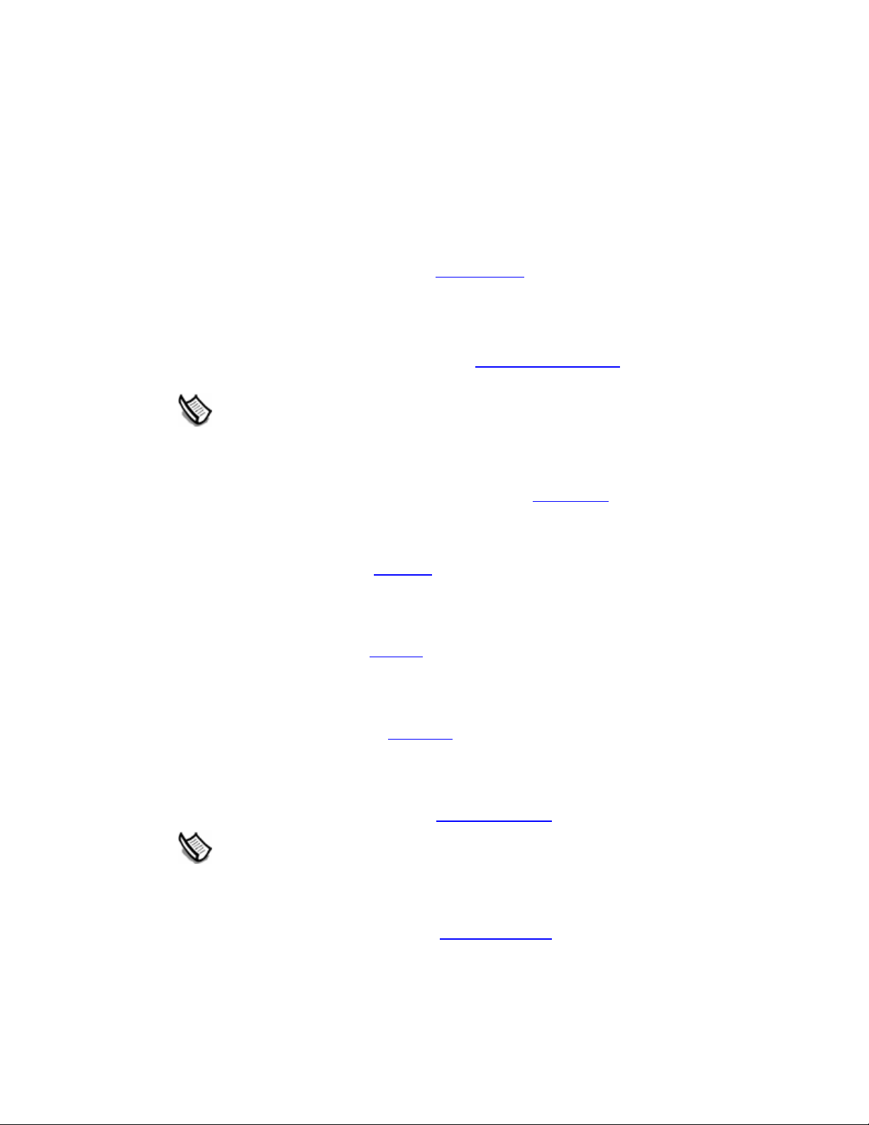
Camera Menu
The Camera menu contains items for altering your point of view of the model.
Previous
Use the Previous menu item to undo the last performed camera command.
Standard
The Standard submenu provides access to standard views: Top, Bottom, Front, Right, Back,
Left, and Isometric. Selecting any of these model views will immediately set your active drawing
window to that view.
Perspective
Use the Perspective menu item to toggle between perspective and paraline projections. You
are in a perspective projection when this item has a checkmark.
Note - SketchUp must be in paraline mode to print to scale. Be aware that faces and
edges that are parallel to the view plane will be measurable.
Application UI
Field of View
Use the Field of View menu item to invoke the Zoom Tool in Field of View mode allowing you to
widen or narrow your field of view.
Orbit
The Orbit menu item invokes the Orbit Tool.
Keyboard Shortcut: O
Pan
The Pan menu item invokes the Pan Tool.
Keyboard Shortcut: H
Zoom
The Zoom menu item launches the Zoom Tool.
Keyboard Shortcut: Z
Zoom Window
The Zoom Extents menu item launches the Zoom Window Tool.
Note - The Zoom Window Tool is not in the SketchUp Mini toolbar, but is available to use
from the Camera menu.
Zoom Extents
The Zoom Window menu item launches the Zoom Extents Tool.
Keyboard Shortcut: Shift+Z
©Google Inc. 2006 Page 53 6/16/2006
Page 62

SketchUp User's Guide
Position Camera
The Position Camera menu item launches the Position Camera Tool allowing you to investigate
fixed views of your model (such the an eye-level view of a house). This option is often used with
the Walk Tool to take an eye-level tour of a structure.
Walk
The Walk menu item invokes the Walk Tool for maneuvering through your SketchUp model a s
though you taking a virtual tour of the model.
Look Around
The Look Around menu item invokes the Look Around Tool which pivots the ca mera around a
stationary point at the point of view.
©Google Inc. 2006 Page 54 6/16/2006
Page 63

Draw Menu
The Draw menu contains all of the SketchUp drawing tools and provides an alternative to using
the Toolbars
Line
The Line menu item invokes a Line Tool used to draw line entities, or edges, within the drawing
area.
Keyboard Shortcut: L
Arc
The Arc menu item invokes a Arc Tool used to draw Arc entities, comprised of multiple
connected straight line segments (editable as a single curve).
Keyboard Shortcut: A
Freehand
Use the Freehand menu item to invoke a Freehand Tool used to draw irregular, coplanar
connected lines in the form of Curve entities
or keyboard shortcuts.
Application UI
.
Rectangle
The Rectangle menu item invokes a Rectangle Tool used to draw four coplanar intersecting
edges and a subsequent Face entity
Keyboard Shortcut: R
Circle
The Circle menu item invokes a Circle Tool used to draw Circle entities.
Keyboard Shortcut: C
Polygon
The Polygon menu item invokes a Polygon Tool used to draw regular Polygon entities,
inscribed within a circle, consisting of 3 to 100 sides.
.
©Google Inc. 2006 Page 55 6/16/2006
Page 64

SketchUp User's Guide
Tools Menu
The Tools menu provides access to all of the modification tools in Sketchup. This menu
represents one of three mechanisms for accessing these tools (a dditional mechanisms are th e
Toolbars
Select
The Select menu item invokes a Select Tool allowing you to select one or more entities to
modify.
Keyboard Shortcut: Spacebar
Eraser
Use the Eraser menu item to invoke the Eraser Tool allowing you to erase entities from the
drawing area
Keyboard Shortcut: E
Paint Bucket
The Paint Bucket menu item invokes the Paint Bucket Tool used to assign materials to entities
in your model. Use the Paint Bucket tool to paint individual elements, fill a number of connected
faces, or replace a material in your model.
and keyboard shortcuts).
. This tool also allows you to hide and soften edges.
Keyboard Shortcut: B
Move
The Move menu item invokes the Move Tool allowing you to move, manipulate, and copy
geometry. This tool can also be used to rotate Component entities
Keyboard Shortcut: M
Rotate
Use the Rotate menu item to invoke the Rotate Tool used to rotate drawing elements and single
or multiple objects within a single rotation plane. The Rotate Tool can also be used to stretch
and distort geometry by selecting only a portion of a model.
Keyboard Shortcut: Q
Scale
The Scale menu item invokes the Scale Tool allowing you to resize and stret ch selected
geometry relative to other elements in your SketchUp model.
Keyboard Shortcut: S
Push/Pull
The Push/Pull menu item invokes the Push/Pull Tool used to manipulate faces of your model.
This tool can be used to displace, extrude, re-attach, or subtract faces, depending on the
context of selected geometry.
.
Keyboard Shortcut: P
Follow Me
Use the Follow Me menu item to invoke the Follow Me Tool used to extrude faces along a path
such as an edge or line drawn with the Freehand Tool
©Google Inc. 2006 Page 56 6/16/2006
. This tool is useful when adding details to
Page 65

a model because it allows you to draw the detail at one end of a path on the model and then
repeat that detail along the path.
Offset
The Offset menu item invokes the Offset Tool used to create copies of co-planar lines and faces
that are a uniform distance from original lines and faces. Lines and faces can be offset either
inside or outside the original face. Offsetting a face will always create a new face.
Keyboard Shortcut: F
Tape Measure
Use the Tape Measure menu item to invoke the Tape Measure Tool used to perform a number
of dimension-related operations. These operations include measuring the distance between two
points, creating Construction Line entities
dimension.
Keyboard Shortcut: T
Protractor
The Protractor menu item invokes the Protractor Tool allowing you to measure angles and
create Construction Line entities
Application UI
, and re-scaling an entire model to an exact
(usually at some angle).
Axes
The Axes menu item invokes the Axes Tool allowing you to move the drawing axes. This tool is
often used when constructing rectangular objects that are skewed relative to one another, or to
allow for more accurate scaling of entities that are not oriented along the default coordinate
planes.
Note - The Axes Tool is not in the SketchUp Mini toolbar, but is available to use from the
Camera menu.
Dimensions
Use the Dimensions menu item to invoke a Dimension Tool used to place Dimension entities in
your model.
Text
The Text menu item launches a Text Tool used to insert Text entities into your model.
Section Plane
The Section Plane menu item invokes a Section plane Tool used to make section cuts in your
model.
Sandbox
The Sandbox submenu contains options for modifying terrain. This menu item only appears
after enabling the terrain modeling tools using the Extensions panel of the Preferences d ialog
box. See the Sandbox Tools topic for further information.
Utilities
The Utilities submenu contains various utilities and macros created using the Sketchup Ruby
API. This menu item only appears after enabling the utilities tools using the Extensions panel of
the Preferences dialog box.
©Google Inc. 2006 Page 57 6/16/2006
Page 66

SketchUp User's Guide
Note - Ruby scripts are contained in the Plugins directory under the installation directory.
Create Face
The Create Face menu item invokes the Create Face utility allowing you to troubleshoot face
creation and, in most cases, create a face for three or more intersecting edges. Specifically, the
Create Face utility is useful when:
• A model has two edges that have a common end point geometrically (the coordi nates of
the end point are the same), but the edges are not connected topologically. In this case, the
Create Face utility will properly connect edges and create a face.
• A face cannot be created because edges are not exactly planer, or appear to be conn ected
when there is actually a small gap between the ends of the edges. In these instances,
Create Face will not create a face, but displays a message indicating why SketchUp cannot
create a face. This message can be used to troubleshoot face creation.
Query Tool
The Query Tool menu item invokes a Query Tool utility that displays the current mouse position
in the VCB.
Fix Non-planar Faces
The Fix Non-planar Faces menu items invokes the Fix Non-planar Faces utility to find and fix
non-planar faces. Fix Non-planer Faces looks at the Vertices of every face and checks to see if
they are on the plane of the face. If not, Check Validity tries to break the face into triangle so
that each triangular face will be planar.
Fix Non-planar Faces can actually change the model, but does not move vertices or edges.
Instead, Check Validity will split faces into triangular faces if they were not planar.
Note - Non-planar faces can get created by a bug in the DWG importer.
©Google Inc. 2006 Page 58 6/16/2006
Page 67

Window Menu
The Window menu contains model settings and managers for your models. Model settings are
dialog boxes with settings that affect the model, such as shadows, display settings, and model
information. Managers are dialog boxes that manage certain aspects of your model such as
pages, layers, materials, and components.
Model Info
Use the Model Info menu item to display the Model Info dialog box used to set settings for your
entire model.
Entity Info
The Entity Info menu item displays the Entity Info dialog box used to view and set settings for
the currently selected entity (or entities).
Materials Browser
The Materials Browser menu item invokes Material Browser used for selecting and applying
colors and materials to your models.
Material Editor
The Material Editor menu item displays the Material Editor dialog box used for editing and
mixing colors and materials.
Application UI
Components
The Components menu item displays used for managing your compone nts.
Layers
Use the Layers menu item to display the Layer Manager used to manage your SketchUp
layers.
Pages
The Pages menu item invokes the Page Manager used to manage pages for a TourGuide
slideshow. The Page Manger will display with the current page highlighted.
Display Settings
The Display Settings menu item invokes the Display Settings dialog box containing options to
activate the face and edge rendering styles. The face rendering styles are wireframe, hidden
line, shaded, shaded with textures, and Monochrome. The edge rendering styles are profile
lines, jitter lines, and extended edges.
Shadow Settings
The Shadow Settings menu item invokes Shadow Settings dialog box for manipulating
shadows in your model.
Soften Edges
The Soften Edges menu item invokes the Soften Edges dialog box used to soften and smooth
edges in your model.
©Google Inc. 2006 Page 59 6/16/2006
Page 68

SketchUp User's Guide
Outliner
The Outliner menu item invokes the Component Outliner used to display component s and
groups in a hierarchy.
Instructor
The Instructor menu item invokes the Instructor used to display informati on about the currently
activated tool.
Preferences
The Preferences menu item invokes the Application Preferences dialog box where you can set
various global settings for the program.
Hide/Show Dialogs
Use the Hide/Show Dialog menu item to hide and show all currently active dialog boxes.
Ruby Console
The Ruby Console menu item displays the Ruby Console where you can type Ruby script.
©Google Inc. 2006 Page 60 6/16/2006
Page 69

Google Menu
The Google menu contains items used to interact with other Google applications.
Get Current View
Use the Get Current View menu item to capture 2D and 3D snapshot images of the current
view in Google Earth.
Toggle Terrain
Use the Toggle Terrain menu item to toggle the Google Earth snapshot image between a 2D
and 3D image.
Place Model
Use the Place Model menu item to place your SketchUp models in Google Earth.
Get Models...
Use the Get Models menu item to download a model from the Google 3D Warehouse.
Share Models...
Use the Share Models... menu item to post your SketchUp model file and corresponding KML
file to the Google 3D Warehouse. The Google 3D Warehouse is a repository where models ca n
be shared with other Google Earth or SketchUp users.
Application UI
©Google Inc. 2006 Page 61 6/16/2006
Page 70

SketchUp User's Guide
Help Menu
The Help menu contains items relating to receiving help with the product. These items include
the SketchUp on-line user's guide, a quick reference card, and video tutorials.
Google SketchUp Help...
The Google SketchUp Help... menu item opens SketchUp's online user's guide.
View Tutorials...
The View Tutorials... menu item launches the Video Tutorials portion of the SketchUp web site.
Select this command to open your default web browser and connect to the SketchUp online
video tutorials.
Quick Reference...
Use the Quick Reference... menu item to display SketchUp's Quick reference card in your
default PDF viewer.
SketchUp Web Site
The SketchUp Web Site menu item invokes your default web browser and connects y ou to the
SketchUp web site
information, and access to new software releases.
. The web site contains SketchUp support forums, additional training
Tip of the Day
The Tip of the Day menu item invokes the Tip of the Day dialog box containing useful
information to help you learn SketchUp.
View Tutorials...
The View Tutorials... menu item launches the Video Tutorials portion of the SketchUp web site.
Select this command to open your default web browser and connect to the SketchUp online
video tutorials.
Help Center...
The Help Center... menu item launches the Google SketchUp Help Center in your default web
browser. This web site contains a list of Frequently Asked Questions (FAQs) and a knowledge
base of technical support issues and solutions.
Send a Suggestion...
The Send a Suggestion... menu item launches the Google SketchUp Help Center in your
default web browser. This web site will prompt you to fill out suggestion form to be submitted to
Google. This form contains fields for your name, email, and a comment related to one of the
following categories: bug report, feature request, comment, training question.
Google SketchUp Community...
The Google SketchUp Community... menu item launches a the SketchUp user's forum in your
default web browser.
Ruby Help
The Ruby Help menu item opens Ruby Help online user's guide. The user's guide contains
reference information for the SketchUp Ruby APIs and examples.
©Google Inc. 2006 Page 62 6/16/2006
Page 71

License
Application UI
The License submenu includes several options allowing you to view and manage your
SketchUp license.
License Info
The License Info menu item displays information about your SketchUp license, including the
type of license and serial number.
Authorize...
Use the Authorize... menu item to authorize your SketchUp licence to extend the use of
SketchUp beyond the 8 hour trial period. Click on this menu item to display the SketchUp
Authorization Screen. Type in the authorization number, provided by Google when you buy
SketchUp, to authorize SketchUp.
Unauthorize...
Use the UnAuthorize... menu item to unauthorize your SketchUp licence. This menu item is
used primarily when switching from a single-user license to a multiuse r network license.
Caution - SketchUp will not run after you unauthorize your license. You must authorize a
new single-user or network license to use SketchUp again.
Set Network License File...
Use the Set Network License File menu item to relocate the network license file on the network.
Unset Network License File
Use the Unset Network License File menu item to delete the location of the network license file
on the network.
Lan License Monitor
The Lan License Monitor menu item displays the LAN License Monitor dialog box. This dialog
box displays single user licenses on the network.
Check Web for Update...
The Check Web For Update... menu item checks to see if you have the most current version of
SketchUp. You will be prompted to download the current version if your version is out-of-date. A
Internet connection is required to use this feature.
Ruby Help
The Ruby Help menu item opens Ruby Help online user's guide. The user's guide contains
reference information for the SketchUp Ruby APIs and examples.
Self-Paced Tutorials
The Self-Paced Tutorials submenu contains three self-paced tutorials allowing you to learn to
use SketchUp.
About Google SketchUp...
The About Google SketchUp... menu item activates the About Google SketchUp dialog box.
This dialog box provides information about your SketchUp version and license.
©Google Inc. 2006 Page 63 6/16/2006
Page 72

SketchUp User's Guide
About Plugins
The About Plugins sub-menu contains information about additional SketchUp plugin s.
Check Web for Update...
The Check Web For Update... menu item checks to see if you have the most current version of
SketchUp. You will be prompted to download the current version if your version is out-of-date. A
Internet connection is required to use this feature.
©Google Inc. 2006 Page 64 6/16/2006
Page 73

Toolbars
SketchUp's toolbars are similar to those in other Microsoft Windows applications in th at each
contains a related set of tools. These toolbars can be detached by clicking and dragging the
move handle (thin line at the top) of the toolbar, resized by dragging the corners, and reattached
or docked to the edge of the drawing area
using the View > Toolbars submenu.
Note - Only the Getting Started and Google toolbars appear when you first run Sketch Up.
You can turn on other toolbars using the Toolbars submenu in the View menu.
Getting Started
The Getting Started toolbar contains all of the tools and menu items necessary for a new user to
become acquainted with SketchUp. These tools are the Select Tool
Tool, Eraser Tool, Tape Measure Tool, Paint Bucket Tool, Rectangle Tool, Circle Tool, Arc
Tool, Push/Pull Tool, Move Tool, Rotate Tool, Offset Tool, Orbit Tool, Pan Tool, Zoom Tool, and
Zoom Extents Tool
Application UI
to suit your preferences. Toggle toolbar visibility
, Make Component, Line
.
Standard Toolbar
The Standard toolbar contains a variety of menu items which help with file and drawing
management, as well as shortcuts to printing and help operations. These menu item s are New
, Save, Make Component, Cut, Copy, Paste, Erase, Undo, Redo, Print, and Model Info.
Open
Principal Toolbar
The buttons on the Principal toolbar activate the Select Tool, Paint Bucket Tool, and Eraser
Tool.
Drawing Toolbar
The buttons on the Drawing toolbar activate the Rectangle Tool, Line Tool, Circle Tool, Arc
Tool, Polygon Tool, and Freehand Tool.
Modification Toolbar
The Modification toolbar contains geometry modification tools. The tools on this toolbar are the
Move Tool
, Push/Pull Tool, Rotate Tool, Follow Me Tool, Scale Tool, and Offset Tool.
,
Construction Toolbar
The buttons on the Construction toolbar activate the Tape Measure Tool, Dimensions Tool,
Protractor Tool
©Google Inc. 2006 Page 65 6/16/2006
, Text Tool, Axes Tool, and Section Tool.
Page 74

SketchUp User's Guide
Camera Toolbar
The buttons on the Camera toolbar activate the Orbit Tool, Pan Tool, Zoom Tool, Zoom
Window Tool, Zoom Extents Tool, and the Previous camera tools.
Walkthrough Toolbar
The buttons on the Walkthrough toolbar activate the Position Camera Tool, Walk Tool, and
Look Around Tool
Display Style Toolbar
The buttons on the Display Style toolbar activate SketchUp's face rendering styles (x-ray
transparency, wireframe, hidden line, shaded, and shaded with textures).
.
Views Toolbar
The buttons on the Views toolbar activate SketchUp's standard views (iso, top, front, right, back,
and left). The bottom view is not included, but is available from the Camera menu
Shadows Toolbar
The Shadows toolbar is used to control shadows. This toolbar contains buttons to launch the
Shadow Settings dialog box (left-most icon) and enable/disable shadows (second icon). This
toolbar also contains slider bars to control settings related to the time of year (left-most slider
bar) and time of day (right-most slider bar).
Sections Toolbar
The Sections toolbar allows you to conveniently execute common section operations. The
controls on this toolbar include buttons for toggling the section cut effect
of section planes
.
and toggling the display
.
Layers Toolbar
The Layers toolbar provides quick access to several often used layer operations.
©Google Inc. 2006 Page 66 6/16/2006
Page 75

Display the Current Layer
When nothing is selected, the current layer name is displayed in the toolbar and has a check
mark next to it. Any new entities you draw will be assigned to the current layer.
Change the Current Layer
Select a layer from the Layers toolbar, when nothing is selected, to change the current layer.
View Entity's Layer
Select an entity. The layer for the entity will be displayed, with a check mark, in the layers
toolbar.
Change the Layer Assignment of Entities
Select an entity and then a layer from the layer toolbar to change the layer of an entity.
Display the Layer Manager
The button on the right hand side displays the Layers Manager allowing you to create new
layers, control their visibility, and more.
Google Toolbar
The buttons on the Google toolbar are used to collaborate between SketchUp and other Google
products. The toolbar contains the Get Current View
and Share Model
Application UI
, Toggle Terrain, Place Model, Get Models,
buttons.
Large Buttons
The toolbar can be displayed using large and small tool buttons. Check the Use Large Tool
Buttons checkbox in the General panel of the Preferences dialog box
and small tool buttons.
Tool Help Tips
Hover over a tool to display a help tag with the name of the tool. A longer help tag will appear in
the Status Bar
to switch between large
when you activate a tool.
©Google Inc. 2006 Page 67 6/16/2006
Page 76

SketchUp User's Guide
Context Menus
Menu items also appear in special context menus which are menus wh ose contents vary
depending on the context in which they are invoked (usually on one or more entities in the
drawing area or within a user interface component, such as a dialog box). The following image
shows a context menu for a Face entity.
Context-Clicking
Context menus are invoked by selecting one or more entities and clicking the right mouse
button. This operation is referred to as a context-click.
Detailed information on the context menu for each entity appears in the Entities
user's guide.
Other dialog boxes and user interface components have their own context menus, inclu ding
drawing axes
section of this
, the Material Browser, and so on.
©Google Inc. 2006 Page 68 6/16/2006
Page 77

Dialog Boxes
Most dialog boxes in SketchUp are modeless, meaning they do not limit your
interaction with the rest of the application by requiring user input before continuing
with your work. Instead, these dialog boxes can be displayed while you work
allowing you to make dynamic settings changes to your model while you are
sketching. Dialog boxes in SketchUp can be snapped to other user interface
components on your screen, resized, and minimized (with some exceptions).
Snapping Dialog Boxes to Other User Interface Components
Some dialog boxes, such as the Display Settings dialog box, automatically snap to the outside
edges of the application window, the outer edge of the screen, with the top and bottom of other
dialog boxes to create a dialog stack. To snap a dialog box to another user interface
component:
1. Display a dialog box, such as the Window > Display Settings dialog box.
2. Click and hold on the dialog box's title bar.
3. Move the dialog box to the outside edge of the application window, outside edge of the
screen, or top or bottom edge of another dialog box (such as the Shadow Settings dialog
box). The dialog box will snap to and align with the edge.
Application UI
Note - Dialog boxes that have been snapped to the application window do not move when
the application window is moved (they are not stuck to the window).
Tip - Snap several dialog boxes together at their top and bottom edges to form a dialog
box stack. Dialog boxes in a dialog box stack move with t he stack when t he top-most
dialog box's title bar is moved.
Manipulating Dialog Boxes in a Dialog Box Stack
A dialog box stack refers to a series of dialog boxes snapped together at their
bottom and top edges such that they form a stack. The following image contains a
dialog box stack with the Shadow Settings dialog box opened in the middle.
You can manipulate the dialog boxes in a dialog box stack in the following ways:
• Move the entire dialog box stack by clicking, holding, and moving the top-most dialog box's
title bar.
• Click on any dialog box's title bar to minimize or maximize a dialog box within the stack.
©Google Inc. 2006 Page 69 6/16/2006
Page 78

SketchUp User's Guide
• Move a dialog box, residing in the middle of the stack, to the right or left to break it from the
stack. Move a dialog box, residing at the bottom of the stack, down to break it from the
stack.
• Reinsert the dialog box at the beginning or end of the stack by snapping the dialog box to
the bottom or top edge of the stack, respectively.
• Reinsert the dialog box in the middle of the stack by moving sideways into a middle
position.
• Snap the entire dialog box stack to the application window or screen by moving it to the
outer edge of the application window or screen.
Resizing Dialog Boxes
Some SketchUp dialog boxes, such as the Component Browser dialo g box, can be resized.
Move the cursor around the dialog box's edges to display a resize curs or (two arrows). Click on
the edge and move the edge to resize the dialog box.
Minimizing Dialog Boxes
Click on any dialog box's title bar to minimize or maximize the dialog box (even those that can
not be placed in a dialog box stack).
©Google Inc. 2006 Page 70 6/16/2006
Page 79

Drawing Axes
SketchUp's drawing axes consist of three colored lines, perpendicular to each other, displayed
in the drawing area
you work.
. These axes are helpful in providing a sense of direction in 3D space while
Application UI
Note - The Drawing Axes will be automatically hidden in any images exported from
SketchUp.
Moving the Drawing Axes
The drawing axes can be manipulated (moved, moved and rotated, and hidden) through their
context menu. To move the drawing axes:
1. Context-click on the Drawing Axes and select Place from the context menu. The cursor
changes to a collection of axes.
2. Move your cursor to the point in your model to be the new coordinate origin. You will see
the axes snap to inferred alignments and points as you move around your model.
3. Click to accept the new coordinate origin.
4. Drag your cursor away from the origin to set an alignment for the red axis. Use the
inference ToolTips to make sure you are aligned precisely.
5. Click to accept the alignment.
6. Move your cursor away from the origin to set an alignment for the green axis. Use inference
ToolTips again to make sure you are aligned precisely.
7. Click again to accept the alignment.
©Google Inc. 2006 Page 71 6/16/2006
Page 80

SketchUp User's Guide
Moving and Rotating the Drawing Axes Relative to Current Position
You can quickly and accurately move and rotate the drawing axes relative to their current
position using the Move Sketching Context dialog box. To move and rotate the drawing axes:
1. Context-click on the drawing axes. The drawing axes context menu is displayed.
2. Select Move from the context menu. The Move Sketching Context dialog box is displayed.
3. Specify displacement and rotation values in the units specified under the Units panel of the
Model Info dialog box.
4. Click OK.
Aligning the Point of View to the Current View
You can align SketchUp's point of view to be perfectly aligned with the current view. To align the
point of view to the current view:
5. Context-click on the drawing axes. The drawing axes context menu is displayed.
6. Select Align View from the context menu.
Hiding the Drawing Axes
You can display or hide the drawing axes from the View menu. You can also hide the drawing
axes from the drawing axes's context menu
(when the drawing axes are visible).
©Google Inc. 2006 Page 72 6/16/2006
Page 81

Inference
SketchUp features a geometric analysis engine, called the inference engine, allowing you to
work in 3D space using a 2D screen and input device. This engine helps you draw very
accurately by inferring points from other points as you draw while also providing you with visual
cues.
Inference Cues
The inference engine uses ToolTip cues, appearing automatically while working on the model,
to identify significant points or geometric conditions. These cues make complex inference
combinations clear to you as you draw
Additionally, the inference engine uses specific colors to indicate its type of inference (covered
further in Inference Types).
Inference Types
There are three main types of inferences: point, linear, and planar. SketchUp often combines
inferences together to form a complex inference.
Point Inference
A point inference is based on an exact point of your cursor in your model.
Application UI
Endpoint: The green Endpoint inference identifies the end of a Line entity
Midpoint: The cyan Midpoint inference indicates the middle point on a line or edge.
Intersection: The black intersection inference indicates an exact point where a line in tersects
another line or face.
On Face: The blue On Face inference identifies a point which lies on a Face Entity
On Edge: The red On Edge inference identifies a point that lies along an edge.
Equi-Distant On Edge: The Equi-Distant On Edge inference indicates an equidistant point, or
a chamfer, when a magenta line appears between two connected edges.
Half Circle: The Half Circle inference appears when drawing an arc to indicate the point that
creates an exact half circle.
or Arc entity.
.
©Google Inc. 2006 Page 73 6/16/2006
Page 82

SketchUp User's Guide
Linear Inference
A linear inference snaps along a line or direction in space. In addition to a ToolTip, a linear
inference sometimes displays a temporary dotted line while you draw.
On Axis: The On Axis inference indicates a linear alignment to one of the drawing axes
solid line is drawn in the color associated with the corresponding axis (red, green, or blue).
From Point: The From Point inference indicates a linear alignment from a point along the
Drawing Axes
axis (red, green, or blue).
Perpendicular: Tie Perpendicular magenta line indicates perpendicular alignment to an edge.
Parallel: The Parallel magenta line indicates a parallel alignment to an edge.
Tangent at Vertex: When drawing from the endpoint of an Arc entity
Tangent to Edge:
Planar Inference
A planar inference snaps to a plane in space.
Drawing Planes: SketchUp will snap to the planes defined by the Drawing Axes
when it cannot snap to geometry in the drawing area. For example, SketchUp will draw on the
ground plane when the point of view is that of the ground plane.
On Face: A blue On Face inference identifies a point which lies on a face. Although initially a
point inference, On Face can also serve as a planar alignment by using inferen ce locking
(described below).
directions. The dotted line is drawn in the color associated with the corresponding
Encouraging an Inference
At times, the inference you need may not come up immediately or SketchUp might choose
alignments with the wrong geometry. In these cases, you can increase the chances of a
particular alignment by pausing your mouse cursor over the particular location that you want
SketchUp to infer from. When the ToolTips appears, SketchUp will briefly prioritize that
alignment as you continue drawing. For example, to encourage SketchUp to create a line to
match another, parallel, line (such as when drawing the third line of a rectangle):
. The
using the Arc Tool.
and your view
©Google Inc. 2006 Page 74 6/16/2006
Page 83

1. Create the first two edges of a rectangle with the first edge being parallel to the red axes.
2. Click on the start point of the third edge and move the line tool as though you were creating
the third line parallel to first line. As you begin to move the line tool, the line should appear
in red.
3. Mid-line creation, move the line tool over the start point of the start point of the first line you
created for the rectangle. Your line will extend diagonally to this point.
4. Leave the tool over this point until the Endpoint ToolTip displays.
5. Move the line tool to the approximate location where the end of the third line should appear.
A dotted line, with the color of the corresponding axes (green) will follow the line tool to
indicate you are directly inline with the start point of the first line.
6. Click when the line you are drawing is indicated by an axes color (red) and is directly
perpendicular to the green dotted line.
Component Inferences
All normal geometry inferences can be obtained from geometry inside Component entities or
Group entities
. Group and Component inferences are all indicated by magenta dots.
Inference Locking
At times, geometry might interfere with your ability to infer points from other points, making it
difficult to draw accurately. Use an inference lock, which tells SketchUp not to waver from the
direction it is currently inferring from, to solve this problem. To use the inference lock, hold down
the Shift key when SketchUp infers the desired alignment (the inference line will bold). The
alignment will remain locked, even as you move the mouse and/or pick a secondary inference
point. The following image shows the inference locked in the blue direction to ensure that a new
line is exactly perpendicular to the face.
Application UI
Any of the inference conditions may be locked; along an axis direction, along an edge direction,
on a face, from a point, parallel or perpendicular to an edge, and so on.
Video - A video tutorial on this topic is available at
http://www.sketchup.com/training/tutorials.php
©Google Inc. 2006 Page 75 6/16/2006
Page 84

Page 85

Principal Tools
This section of the user's guide covers the principal tools within SketchUp. Principal t ools are
those tools that tend to be used most often in SketchUp.
Tools in this section are covered in the order they appear within the Tools menu.
©Google Inc. 2006 Page 77 6/16/2006
Page 86

SketchUp User's Guide
Select Tool
Use the Select Tool to specify the entities you will modify when using other tools or commands.
The entities that are included in a selection are referred to as the selection set. Activate the
Select Tool from the Principal toolbar
Keyboard Shortcut: Spacebar
Selecting a Single Entity
SketchUp allows you to make both single-entity and multiple-entity selections. To select a single
entity:
1. Select the Select Tool. The cursor changes to an arrow.
2. Click on an entity. The selected entity is highlighted in yellow.
Selecting Multiple Entities
Multiple-entity selections are useful when you want to perform a single operation on several
entities (the selection set). Multiple-entity selections use an expandable selection box to
surround the entities you want in the selection set. To select multiple entities:
1. Select the Select Tool. The cursor will change to an arrow.
or from the Tools menu.
2. Click and hold the mouse button a short distance away from the entities you want to select
to start a selection box.
3. Drag the mouse to expand the selection box over the elements you want to select.
a. Clicking to the right-side and dragging to the left, called a crossing selection,
selects any elements within the selection rectangle, including those that are
only partially contained in the rectangle. The following images show a right-toleft selection selecting two components, though none are completely within
the bounds of the selection box.
©Google Inc. 2006 Page 78 6/16/2006
Page 87

Principal Tools
b. Clicking to the left-side of the entities and dragging right, called a
window selection, selects only those elements completely within the selection
rectangle. The following image shows a left-to-right selection selecting one
component because only one component (the left speaker) is completely
within the bounds of the selection box.
©Google Inc. 2006 Page 79 6/16/2006
Page 88

SketchUp User's Guide
4. Release the mouse button when all of the elements are either partially included (left-to-right
selection) or fully included (right-to-left selection) in the selection box.
Adding and Subtracting From a Selection Set
The Select Tool can be used with one or more keyboard modifiers to add or remove entities
from a selection set.
Adding to the Selection Set (Ctrl)
Press and hold the Ctrl key (the cursor will change to an arrow with a plus sign) while clicking on
additional entities to add entities, one-by-one, to the selection set. Or, press and hold the Shift
key (the cursor will change to an arrow with a plus and minus signs) while clicking on additional
entities to add entities, one-by-one, to the selection set.
Changing Selection Status for an Entity (Shift)
Press and hold the Shift key (The cursor will change to an arrow with plus and minus signs)
while clicking on entities to invert the selection status of the entity (currently selected entities will
become unselected, unselected entities will be come selected).
Subtracting from the Selection Set (Shift+Ctrl)
Press and hold the Shift and Ctrl keys simultaneously (the cursor will change to an arrow with a
minus sign) while clicking on currently selected entities to remove entities from the selection set.
©Google Inc. 2006 Page 80 6/16/2006
Page 89

Or, press and hold the Shift key (the cursor will change to an plus sign and minus sign) while
clicking on currently selected entities to remove the entities, one-by-one, from the selection set.
Tip - Use the Group entity to group items within a selection set as a temporary way of
quickly reselecting the same group of items. See the Group entity for additional
information.
Expanding the Selection Set Using the Mouse
You can automatically add to a selection set clicking the Select Tool multiple times in rapid
succession. Click once on an entity to select that entity. Click rapidly twice (double-click) on an
entity, namely an edge or face, to select corresponding faces or edges respectively. Click three
times (triple-click) on an entity, namely an edge or face, to select he edge or face and all entities
physically connected to that edge or face. The following image shows this cli ck/selection
sequence.
Principal Tools
Tip - Use a context-click to invoke the context menu for an entity. Many context menus
have a Select submenu allowing you to expand a selection usi ng one of the following
commands: Bounding Edges, Connected Faces, All Connected, All on same layer, an d All
with same material.
Selecting or Unselecting All Geometry
Use either the Select All menu item in the Edit menu or press Ctrl+A on the keyboard to select
all visible elements in your model.
Use the Deselect All menu item in the Edit model, press Ctrl+T , or click on any empty space in
the Drawing Area to de-select all currently selected entities.
©Google Inc. 2006 Page 81 6/16/2006
Page 90

SketchUp User's Guide
Eraser Tool
Use the Eraser Tool to delete entities. The Eraser Tool can also be used to hide and soften
edges. Activate the Eraser Tool from the Principal toolbar
menu.
Keyboard Shortcut: E
Erasing Entities
As mentioned previously, the Eraser Tool is used to erase entities in the drawing area. Note, the
Eraser Tool does not allow you to erase faces (faces are erased after their bounding e dges are
erased). To erase entities:
1. Select the Eraser Tool. The cursor changes to an eraser with a small box.
2. Click on an entity to erase it. Alternatively, erase several entities at once by holding down
the mouse button and dragging it over several entities to be erased. All selected geometry
will be erased once you release the mouse button.
If you accidentally select geometry you do not wish to delete, press the ESC key to cancel the
erase operation before it deletes your selection.
, or by selecting Eraser from the Tools
Tip - Try erasing entities slowly if you continuously skip over entities yo u want to erase.
Tip - It is usually faster to erase a large number of entities by selecting the entities with the
Select Tool
items by selecting Erase from the Edit menu.
and pressing the Delete key on your keyboard. You ca n also delete selected
Hiding Lines
Press and hold the Shift key and use the Eraser Tool to hide lines (instead of erasing lines).
Softening/Unsoftening Edges
Press and hold the Ctrl key to soften/smooth edges (instead of erasing entities). Press and hold
the Shift and Ctrl keys simultaneously to unsoften/unsmooth edges.
©Google Inc. 2006 Page 82 6/16/2006
Page 91

Paint Bucket Tool
Use the Paint Bucket Tool to assign materials and colors to entities in your model. You can use
it to paint individual entities, fill a number of connected faces, or replace a material with another
throughout your model. Activate the Paint Bucket Tool from the Principal toolbar
choosing Paint Bucket from the Tools menu
Keyboard Shortcut: B
Video - Various video tutorials on this topic are available at
http://www.sketchup.com/training/tutorials.php
Applying Materials
Ensure you are using either the Shaded or Shaded with Textures display setting so that you can
see materials as they are applied to your model (Window > Display Settings > Shade d or
Shaded with Textures). To apply materials:
1. Select the Paint Bucket Tool. The cursor will change to a paint bucket and the Material
Browser is activated. The Materials Browser contains libraries of materials you can paint on
faces in your model.
Principal Tools
, or by
.
2. Select a materials library using the drop down list in the Materials Browser. SketchUp
contains several default materials libraries, including landscape, roofing, and transparent
materials.
3. Select a material from the materials library.
4. Click on the faces to paint. The material is assigned to the face.
Face Painting Rules
There are several face painting rules that apply when painting multiple faces or edges at the
same time. These rules follow:
• The side of the faces that will be painted depends on the side initially painted when more
than one face is selected. For example, if all faces are selected and you paint the front of
one face, the front of all faces will be painted. Conversely, if all faces are selected and you
paint the back of one face, all back faces will be painted.
• All selected edges will be painted when you select a face and all edges and pai nt the front
of the face. No edges are painted when you select a face and all edges and pai nt the back
of one face. Ensure you have the Window > Display Settings > Edge color set to By
Material to see the painted effect applied to edges.
Fill Options
The Paint Bucket Tool can be used with one or more keyboard modifiers to perform various
painting operations.
Element Fill
The Paint Bucket Tool normally operates by filling in faces as you click on them. As mentioned
previously, entities selected with the Select Tool
Bucket Tool.
©Google Inc. 2006 Page 83 6/16/2006
can be painted with a single click of the Paint
Page 92
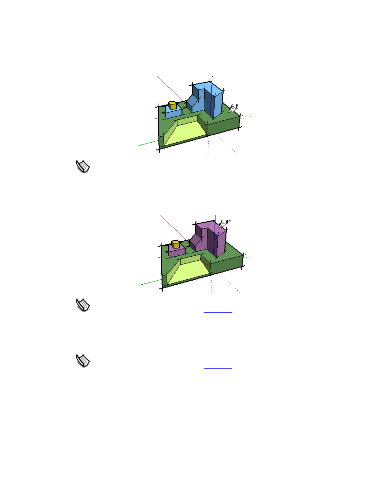
SketchUp User's Guide
Adjacent Fill
Press and hold the Ctrl key while clicking on a face with the Paint Bucket Tool to fill that face
and any adjacent (connected) face with the same material. The face you click on and the
adjacent face must have the same material prior to performing this operation.
Note - Selecting a number of entities with the Select Tool and painting using the Ctrl
modifier keys causes just the entities within the selection set to be painted.
Replace
Press and hold the Shift key prior to clicking on a face with the Paint Bucket Tool to apply a
material to every face, with the same material in the current context, with the new material.
Note - Selecting a number of entities with the Select Tool and painting using the Shift
modifier key causes just the entities within the selection set to be painted.
Adjacent Replace
Press and hold both the Shift and the Ctrl keys simultaneously while painting to only replace the
material on the face within the confines of geometry that is physically connected to that face.
Note - Selecting a number of entities with the Select Tool and painting using the Ctrl
modifier keys causes just the entities within the selection set to be painted.
Sampling a Material
Press and hold the Alt key to change from the Paint Bucket Tool to a Sample Tool for sampling
materials within your model. The cursor will change to an eye dropper. Click on the face whose
material you want to sample. Release the Alt key to return to the Paint Bucket Tool. Paint the
sampled material on a face.
©Google Inc. 2006 Page 84 6/16/2006
Page 93

Painting Groups and Components
Materials can be painted on entire Group entities or Component entities or to the individual
entities within the Group or Component. To assign materials to an entire Group or Component:
1. Select the Paint Bucket Tool. The cursor will change to a paint bucket and the Material
Browser is activated. The Materials Browser contains libraries of materials you can paint on
faces in your model.
2. Select a materials library using the drop down list box. SketchUp contains several default
materials libraries, including landscape, roofing, and transparent materials.
Principal Tools
3. Select a material from the library of materials.
4. Click on the Group or Component you want to paint. The faces will receive the material.
5. If you select multiple Groups or Components using the Select Tool
with the Paint Tool will paint all of them with a single click.
Note - If a face within a Group or Component is already painted with a material (other than
the default material), before applying a material to the entire Group or Component, the
face will not adopt the new material. For example, the windshields, bumpers, and tires in
the following image were already painted before a material was applied to these
components. Therefore, the windshields, bumpers, and tires maintained their original
material.
Note - Exploding a Group or Component assigns the object materials to any el ements
assigned the default material, thus making the material override permanent.
, clicking on the selection
©Google Inc. 2006 Page 85 6/16/2006
Page 94

Page 95

Drawing Tools
This section of the user's guide covers the drawing tools within Sketch Up. Drawing tools are
those tools used to create new geometry. These tools include the Line Tool, Rectangle Tool,
and Freehand Tool.
Tools in this section are covered in the order they appear within the Draw menu.
©Google Inc. 2006 Page 87 6/16/2006
Page 96

SketchUp User's Guide
Line Tool
Use the Line Tool to draw edges or Line entities. Line entities can be joined to form a face. The
Line Tool can also be used to divide faces or heal deleted faces. Activate the Line Tool from
either the Drawing toolbar
Keyboard Shortcut: L
Drawing a Line
Lines can be placed on existing faces or separate from ex isting geometry. To draw a Line:
1. Select the Line Tool. The cursor changes to a pencil.
2. Click to set the starting point of your line.
Note - Press the Esc key at any point during the operation to start over.
3. Move the cursor to the ending point of your line. As you draw a line, the length is displayed
dynamically in the Value Control Box (VCB).
4. Click to draw your line. This ending point can also be the starting point of another line.
or the Draw menu.
The line length can be specified precisely using the VCB either before clicking the second point
or immediately after the line has been drawn. See Specifying Precise Line Values
information on using the VCB with Line entities.
Tip - Alternately, you can click and hold the mouse button to set the starting point of the
line, and drag outward without releasing the button to set the length. Release the mouse
button to complete the line. See the Drawing panel of the Preferences dialog box
further information on setting drawing behavior.
Creating a Face
The Line Tool will remain at the ending point of every line you create. This end point is
automatically treated as a starting point for another line. You can create another line by moving
the cursor and clicking again from this new starting point. These two lines are said to be
coplaner, intersecting lines (intersecting at starting and ending points).
Three or more coplanar lines, intersecting at their ending and starting points (forming a loop),
generate a Face entity
close a Face entity to ensure that any lines you draw are continuous. The Line Tool is released
but is still active after a face has been created.
for further
for
. Ensure that the Endpoint inference ToolTip is visible whenever you
©Google Inc. 2006 Page 88 6/16/2006
Page 97

Tip - Set the display settings (Window > Display Settings ) to the Shaded rendering st yle
to clearly show new faces as they are created.
Splitting a Face
Draw a line with starting and ending points on the face's edges to split a face. The following
image shows a rectangle being split when a line is drawn from one edge of a face to another
opposite edge.
Integrating Lines
Occasionally, overlapping lines will not be split or integrate with a face. Any lines that are not
part of a face perimeter will be displayed with a thicker line (left-most image below) . The Profile
Edge rendering style must be enabled in the Display Settings dialog box
Drawing Tools
to see this behavior.
Use the Line Tool to trace along an existing line to attempt to split overlapping lines. SketchUp
will re-analyze your geometry and attempt to reintegrate the line. The following images show a
bold line that did not effectively split a face (left-most image). The line was traced (middleimage) and the line became thin indicating that the line was reintegrated.
Splitting a Line
SketchUp automatically splits line segments when new lines are drawn perpendicular to a line.
For example, draw a new line to the midpoint (identified by a cyan square) of another line to split
a line in half. The following example shows one line being intersected at the midpoint, resulting
in two lines.
Select the original line to verify that the line has been split into two equal segments.
©Google Inc. 2006 Page 89 6/16/2006
Page 98

SketchUp User's Guide
Dividing a Line into Equal Segments
Line segments can be divided into any number of equal line segments. To divide a line into
equal segments:
1. Context-click on a line.
2. Select Divide from the context menu. SketchUp will place points on the line to show where
the line will be divided.
3. Move the cursor toward the center of the line to reduce the number of segments. Move
cursor toward either end of the line to increase the number of segments.
4. Click on the line when the number of segments you would like is shown. The line will be
divided into an equal number of joined line segments.
Specifying Precise Line Values
The VCB displays the length of your line while you are drawing lines. You can also specify an
line length value using the VCB.
Entering a Length Value
The VCB label indicates "Length" after you place the starting point of a line. The following image
shows the length value in the VCB.
Type the length into the VCB, after placing the starting point of the line, and press the Enter or
Return key. SketchUp will use the current document units setting if you only type in a numerical
value. You can also specify either Imperial (1’6”) or Metric (3.652m) units at any time,
regardless the model units setting.
Note - The Line Tool will snap to any previously entered length within the VCB.
Entering a 3D Coordinate
The VCB can also be used to place the end of the line at an exact coordinate in space.
Entering an Absolute Coordinate: Type in the coordinates of a point in 3D space enclosed by
brackets, such as [x, y, z], to get absolute coordinates relative to the current axes.
Entering a Relative Coordinate: Type the coordinate points enclosed by angle brackets, in the
format <x, y, z>, where x, y, and z values are relative distances from the starting point of your
line.
Note - The exact format for VCB entries will vary depending on your computer's Regi onal
Settings. For European users, the list separator symbol may be a semi-colon instead of a
comma, so the format would be
[x; y; z].
Drawing Lines by Inference
The Line Tool uses SketchUp's sophisticated geometric inference engine to help you place your
lines in 3D space. The inference decisions, made by the inference engine, are di splayed in the
drawing area
©Google Inc. 2006 Page 90 6/16/2006
as inference lines and inference points. These lines and points show precise
Page 99

Drawing Tools
alignment between the line you are drawing and the geometry of your model. Refer to the
inference engine
Locking a Line to the Current Inference Direction
Press and hold the Shift key, while the line you are drawing is the specific color of an axis, to
lock drawing operation to that axis.
Locking a Line to a Specific Inference Direction
Press and hold either the up arrow, left arrow, or right arrow keys, where the up arrow equals
blue, left arrow equals green, right arrow equals red, while drawing a line to lock the line to a
specific axis.
topic for additional information.
©Google Inc. 2006 Page 91 6/16/2006
Page 100

SketchUp User's Guide
Arc Tool
Use the Arc Tool to draw Arc entities, comprised of multiple line segments (which can be edited
as a single arc). Activate the Arc Tool from the Drawing toolbar
Keyboard Shortcut: A
Drawing an Arc
Arc entities consist of three parts: the starting point, the ending point and the bulge distance.
The distance between the starting point and the ending point is also known as the chord length.
To draw an arc:
1. Select the Arc Tool. The cursor changes to a pencil with an arc.
2. Click to place the starting point of your arc.
3. Move the cursor to the ending point of your chord.
4. Click to place the ending point of your arc. A straight line is created.
5. Move your cursor perpendicular to the straight line to adjust the bulge distance. A straight
line will extend perpendicular from the straight line.
or from the Draw menu.
Note - Press the Esc key at any point during the operation to start over.
6. Click to set the bulge distance.
Chord length can be specified after you place the ending point of your arc. Bulge
distance, radius, and number of segments can be specified using the VCB
immediately after a arc is drawn. See Specifying Precise Arc Values
information on manipulating arcs using the VCB.
Drawing a Half-Circle
The arc temporarily snaps to a half-circle as you pull out a bulge distance. Watch for the HalfCircle inference ToolTip indicating when your arc is a half-circle.
for more
©Google Inc. 2006 Page 92 6/16/2006
 Loading...