

Page 1
Digital oil control valve
Instruction Manual
WARNING:
Read carefully and understand all INSTRUCTIONS before operating. Failure to follow the safety
rules and other basic safety precautions may result in serious personal injury.
Save these instructions in a safe place and on hand so that they can be read when required.
Keep these instructions to assist in future servicing.
REV 12/05/16
Page 2

GENERAL SAFETY REGULATIONS
WARNING: The warnings, cautions, and instructions
discussed in this instruction manual cannot cover all
possible conditions or situations that could occur. It
must be understood by the operator that common
sense and caution are factors that cannot be built into
this product, but must be supplied by the operator.
1. Keep the work area clean and dry. Damp or wet work areas can result in
injury.
2. Keep children away from work area. Do not allow children to handle this
product.
3. Use the right tool for the job. Do not attempt to force small equipment to do
the work of larger industrial equipment. There are certain applications for
which this equipment was designed. It will do the job better and more safely
at the capacity for which it was intended. Do not modify this equipment, and
do not use this equipment for a purpose for which it Was not intended.
4. Check for damaged parts. Before using this product, carefully check that it
will operate properly and perform its intended function. Check for damaged
parts and any other conditions that may affect the operation of this product.
Replace damaged or worn parts immediately.
5. Do not overreach. Keep proper footing and balance at all times to prevent
tripping, falling, back injury, etc.
6. DO NOT use the equipment when tired or under the influence of drugs,
alcohol, or medication. A moment of inattention while operating this
equipment may result in serious personal injury
Page 3
TECHNICAL DETAILS
Item No.
Inlet
Configure
Flow Rate
Operating Pressure Range
Max Operation Temperature
Accuracy
Battery
This manual contains important warnings and information.
Read and keep for reference.
Warning Symbol
This symbol alerts you to the possibility of serious injury or death if you do not follow the
instructions.
Caution Symbol
This symbol alerts you to the possibility of damage to or destruction of
equipment if you do not follow the instructions.
18123521G
1/2” BSP / NPT
Flexible nozzle, auto tip
1-35L/min / 0.3~9.2gpm
0.5-100bar / 7-1500psi
60°C / 140°F
±0.5%
ER14250 3.6V
SAFETY PRECAUTIONS
EQUIPMENT MISUSE HAZARD
1. This equipment is for professional use only.
2. Read all instruction manuals, tags, and labels before operating the equipment.
3. Use the equipment only for its intended purpose. If you are not sure, call your distributor.
4. Do not alter or modify this equipment.
5. Check equipment daily. Repair or replace worn or damaged parts immediately.
6. Do not exceed the maximum working pressure of the lowest rated system component. This
equipment has a 1500psi (10Mpa, 100bar) maximum working pressure.
7. Use fluids and solvents which are compatible with the equipment wetted parts. Refer to the
Technical Data section of all equipment manuals. Read the fluid and solvent manufacturer’s
warnings.
8. Route hose away from traffic areas, sharp edges, moving parts, and hot surfaces.
9. Do not lift pressurized equipment.
10. Comply with all application local, state, and national fire, electrical, and safety regulations.
INJECTION HAZARD
Spray from the valve, leaks or ruptured components can inject fluid into your body and cause
extremely serious injury, including the need for amputation. Fluid splashed in the eyes or on
the skin can also cause serious injury.
1. Fluid injected into the skin might look like just a cut, but it is a serious injury. Get immediate
medical attention.
2. Do not point the valve at anyone or at any part of the body.
3. Do not put your hand or fingers over the grease fitting coupler.
4. Do not stop or deflect leaks with your hand, body, glove or rag.
5. Tighten all fluid connections before operating the equipment.
6. Check the hose, tubes, and couplings daily. Replace worn or damaged parts immediately.
Do not repair high pressure couplings; you must replace the entire hose.
DETAILS
TECHNICAL
SAFETY
PRECAUTIONS
INSTALLATIONOPERATION
TROUBLE
SHOOTING GUIDE
LIMITED
WARRANTY
E1
EXPLODED AND
PARTS LIST
Page 4
INSTALLATION
7
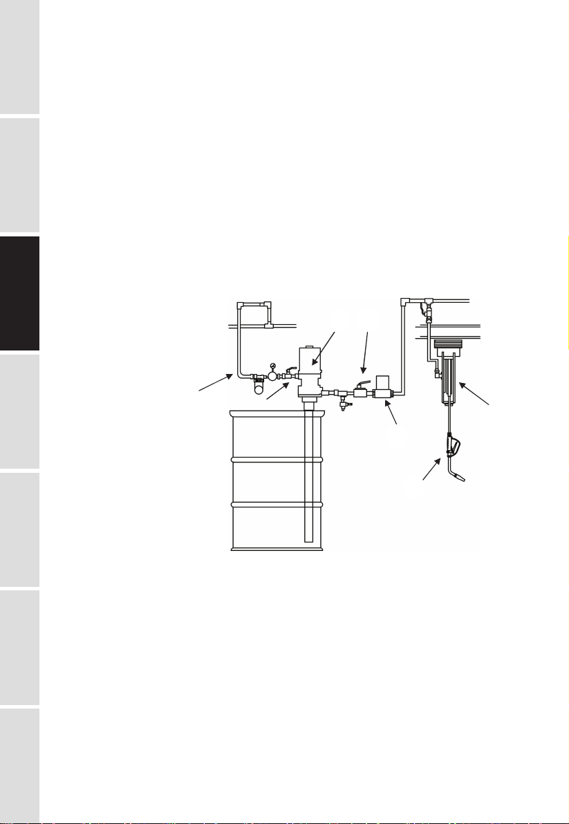
Typical Installation
DETAILS
Fig. 1 shows a typical installation.
TECHNICAL
The installation shown in Fig. 1 is only a guide. The components shown are typical; however, it
is not a complete system design. Contact your distributor for assistance in designing a system
to suit your particular needs.
Pre-Installation Procedure
1. Relieve the pressure.
To reduce the risk of serious injury whenever you are instructed to relieve pressure, always
SAFETY
follow the pressure relief procedure on page 3.
1. Close the fluid shut-off valve (Item 4 in Fig.1)
PRECAUTIONS
2. Ground the hose and reel or console. Do not use PTFE tape on the pipe joints; it may cause
a loss of ground across the pipe joint.
Installation Procedure
If this is a new installation, or if the oil in the lines is contaminated, flush the lines before you
install the dispense valve.
1: Air inlet
2: Air shut-off valve
INSTALLATIONOPERATION
3: Oil pump
4: Fluid shut-off valve
5: Meter
6: Hose reel
7: Control valve
TROUBLE
SHOOTING GUIDE
NEW INSTALLATION
1. Relieve the pressure
To reduce the risk of serious injury whenever you are instructed to relieve pressure, always
follow the pressure relief procedure on page 3.
2. Close the fluid shut-off valve at each dispense position.
3. Make sure the main fluid outlet valve at the pump is closed, the air pressure to the pump
LIMITED
EXPLODED AND
motor is adjusted, and the air valve is open. Slowly open main fluid valve.
4. Place the hose end (with no dispense valve connected) into a container for waste oil. Secure
WARRANTY
the hose in the container so it will not come out during flushing. If you have multiple dispense
positions, first flush the dispense position farthest from the pump, and work your way toward
the pump.
5. Slowly open the shut-off valve at the dispense position. Flush out a sufficient amount of oil to
ensure that the entire system is clean, and close the valve.
6. Repeat step 5 at all other dispense positions.
E2
PARTS LIST
Fig. 1
Page 5

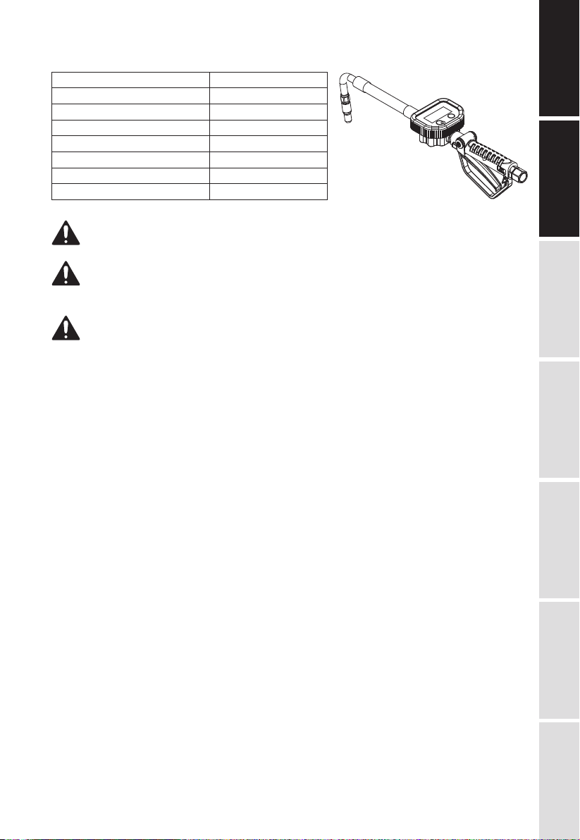
1: Trigger
1
2: Nozzle
3: Tip
4: Swivel nut
Fig. 2
Remark: If you want to adjust the angle of the nozzle, you can loose the #4 swivel nut, then
turn thenozzle to your desired position and tighten the nut.
Existing Installation
1. Relieve the pressure
To reduce the risk of serious injury whenever you are instructed to relieve pressure, always
follow the pressure relief procedure on page 3.
2. Loosen and disconnect the hose from the old dispense valve (the one that you are replacing)
3. Thread the extension into the outlet of the dispense valve, and tighten firmly. NOTE: Do not
over tighten the extension tube assembly by using the nozzle adapter to hand turn the
nozzle. For rigid extensions, thread the extension in at least three full turns, position the
extension for proper alignment, and tighten the sealing nut. The PTFE seal on the sealing
nut must face the valve housing.
4. Apply thread sealant to the male threads of the hose fitting, thread the hose fitting into the
swivel, and tighten firmly.
5. Thread the new nozzle or nozzle adapter onto the extension, and tighten firmly.
6. Open all dispense position shut-off valves, and start the pump to pressurize the system. See
the Operation section for proper operation.
7. For metered dispense valves, to ensure dispensing accuracy, purge all air from the fluid
lines and dispense valves before you use them.
Grounding
Proper grounding is an essential part of maintaining a safe system.
To reduce the risk of static sparking, ground all system components per local and national
electrical codes.
Refer to the user manuals for the pump and other system components to ground the following:
- Pump: Follow manufacture’s recommendations.
- Air and Fluid hoses: Use only grounded hoses.
- Air compressor: Follow manufacture’s recommendations
- Fluid supply container: Follow your local code.
- To maintain grounding continuity when flushing or relieving pressure, always hold a metal part
of the valve firmly to the side of a grounded metal pail, then trigger the valve.
DETAILS
TECHNICAL
SAFETY
PRECAUTIONS
INSTALLATIONOPERATION
TROUBLE
SHOOTING GUIDE
OPERATION
CAUTION
- Never operate the meter with the plastic cover removed. The cover protects the meter from
damage due to impact. Meters are factory sealed to keep moisture and dirt out.
- To prevent line contamination, which can cause equipment malfunction or damaged, flush the
lines before you install this equipment in the system.
LIMITED
E3
EXPLODED AND
WARRANTY
PARTS LIST
Page 6

Display and Button Usage
DETAILS
TECHNICAL
AREA 1: FOR LAST DISPENSE CYCLE AREA 2: FOR MEASUREMENT UNITS
AREA 4: FOR BATTERY
AREA 3: FOR ACCUMULATED
TOTAL
CAPACITY
Notes: It will flashing when
battery voltage less than 3.3V;
SAFETY
PRECAUTIONS
Menu: MOVING THE NUMBERS FOR
ADJUSTING THE CALIBRATION AND
CHOOSING THE UNITS
Reset: CHOOSING THE UNITS AND SETTING
CORRECTION FACTOR
To Activate the Digital Display
Press the RESET key pad to clear the meter before starting a new dispense cycle. This is the
best way to activate the meter, because it also clears the quantity of the last dispense cycle.
The digital display can also be activated by pressing the MENU key pad or by running fluid
through the meter.
INSTALLATIONOPERATION
Calibrating Automatically
- Press Reset key for 1 second and Area 1 shows .000 L;
- Keep running fluid through the meter until the fluid running out of the certain measuring
cylinder. The display will show certain value as *.**L, press the Menu key for 3 seconds. The
meter will enter instrument calibration mode and Area 1 shows 00*.**L;
- Press Menu key to move the flashing digital, press Reset key to choose number, enter the
fluid volume and press Menu key again for 3 seconds, then exit the calibration mode. The
calibration settled
Show Current Correction Factor
- Press Menu key and Reset key together. The display will show the correction factor, which
can be reset
Reset The Resettlement Total
- Press Menu key for 10 seconds, the accumulated total will be reset to be “0”
TROUBLE
To Change the Measurement Units (L / GAL/ PT / QT meter only)
- Move the flashing display to Area 2 by pressing Menu key, then press Menu key to choose
SHOOTING GUIDE
measurement unit
- Press Menu key over 3 seconds to exit the setting mode
CAUTION
- To be sure the proper amount of fluid is dispensed, always use the same measurement unit
for a particular fluid. Units should be changed only by authorized employees.
- To Verify the Accuracy of an Digital Meter
LIMITED
WARRANTY
- Use a clean, calibrated container. If using a single container, be sure to clean it after each
dispense.
- Have pump air pressure at the lowest possible setting for dispensing fluid.
- Put the tip of the nozzle at the bottom of the calibrated container.
- If the tip of the dispense valve does not reach the bottom of the calibrated container, use a
length of plastic tubing over the tip of the nozzle to ensure liquid enters the container from the
bottom.
E4
PARTS LIST
EXPLODED AND
Page 7

- Trigger the gun slowly so the fluid immediately covers the tip of the dispense valve.
Pressure Relief Procedure
Pressurized Equipment Hazard
The equipment stays pressurized Fluid under high pressure can be injected through the skin
and cause serious injury. To reduce the risk of an injury from injection, splashing fluid, or
moving parts, follow the pressure relief procedure whenever you:
- Are instructed to relieve pressure,
- Check, clean or service any of the system equipment,
- Install or clean the nozzle.
1. Turn off the power supply to the pump.
2. Trigger the valve into a waste container to relieve pressure.
3. Open any bleed-type master air valves and fluid drain valves in the system.
4. Leave the drain valve open until you are ready to pressurize the system.
If you suspect that the dispensing valve, extension, or nozzle is clogged or that pressure has
not been fully relieved after following the steps above, very slowly loosen a fitting on the fluid
line to relieve pressure gradually, then loosen it completely, then clear the clog.
To reduce the risk of a serious bodily injury, including fluid injection, never exceed the
maximum working pressure of the valve you are using or of the lowest rated component in your
system.
Dispensing Procedure
Note: Before you begin, make sure you understand how to unlock the trigger.
1. Pull the trigger toward the valve body to open the valve and begin dispensing.
2. Lock the valve open by keeping the trigger squeezed and depressing the trigger lock button.
Then release the trigger, releasing your forefinger from the trigger lock last.
3. Pull the trigger toward the valve body to release the trigger lock. The trigger lock
disengages. Release the trigger to stop dispensing.
DETAILS
TECHNICAL
SAFETY
PRECAUTIONS
INSTALLATIONOPERATION
TROUBLE
LIMITED
E5
EXPLODED AND
SHOOTING GUIDE
WARRANTY
PARTS LIST
Page 8

TROUBLE SHOOTING GUIDE
Relieve the pressure before you check or repair the dispensing valve. Be sure all other valves
DETAILS
and controls and the pump are operating properly.
TECHNICAL
To reduce the risk of serious injury whenever you are instructed to relieve pressure, always
follow the pressure relief procedure on page 3.
Problem
Slow or no fluid flow
Oil leaks from swivel
SAFETY
PRECAUTIONS
Oil drips from nozzle
Valve leaks
INSTALLATIONOPERATION
Leakage from meter
No Display
TROUBLE
SHOOTING GUIDE
Wrong Reading
Problem
Filter is clogged, or pump pressure is low,
or shut-off valve is not fully open, or
foreign materialis jammed in the
metering element.
Swivel is loose
O-ring is worn or damaged
Nozzle is damaged or obstructed
O-rings or valve seat are worn or damaged
O-ring damaged
Loosing Battery
Battery out of power
correction coefficient error
Solution
1. Relief the pressure.
2. Loose swivel fitting, clean or replace the filter.
3. If the problem remains, contact your
distributor for repair or replacement.
Torque the swivel
If the problem remains, contact your distributor
for repair or replacement
Replace the o-ring.
If the problem remains, contact your distributor
for repair or replacement
Inspect the nozzle for damage or obstructions,
and replace if damaged
If the problem remains, contact your distributor
for repair or replacement
Replace the o-rings and/or the valve seat.
If the problem remains, contact your distributor
for repair or replacement
1. Get the meter off from the dispense system
2. Take off the protector
3. Loosing four the socket head cap screws on
the cover of the meter
4. Loosing eight the hex bolts on the bottom of
the meter
5. Take off the seat
6. Check the o-ring, replacing the o-ring if it is
damaged
7. After replacing the o-ring, assemble the meter
and fix it back to the dispense system
1. Get the meter off from the dispense system
2. Take off the protector
3. Take off the labels sticks on the bottom of the
meter
4. Loosing the five socket head cap screws on
the bottom of the meter
5. Take off the seat
6. Check the battery, replacing the battery if it is
out of power
7. After replacing the battery, assemble the
meter and fix it back to the dispense system
Reset the correction factor (follow the
instructions on Page 6)
LIMITED WARRANTY
LIMITED
1. The manufacturer warrantees this product against defects in material and craftsmanship, for
WARRANTY
a period of five years from date of purchase, but not including wearing parts.
2. Manufacturer’s liability is limited to replacement or repair of defective material within the
warranty period, when returned freight prepaid to the distributor or their designated service
depot.
3. The warranty does not cover damage caused by accident, misuse or faulty installation.
4. The product must be installed and maintained in compliance with the instructions.
E6
PARTS LIST
EXPLODED AND
Page 9

EXPLODED AND PARTS LIST
3-4
3-6
3-19
3-8
3-21
3-20
3-3
3-9
3-18
3-14
3-7
4
1-5
DETAILS
TECHNICAL
1-10
1-11
1-121-9
1-13
1-1
1-14
SAFETY
1-2 1-82
1-3
PRECAUTIONS
3-5
3-2
3-16
3-13
3-12
3-11
3-17
3-15
3-1
3-10
1-4
1-7
1-6
INSTALLATIONOPERATION
TROUBLE
SHOOTING GUIDE
LIMITED
WARRANTY
E7
EXPLODED AND
PARTS LIST
Page 10

Part No.
1-1
DETAILS
TECHNICAL
SAFETY
1-2
1-3
1-4
1-5*
1-6
1-7*
1-8
1-9
1-10*
PRECAUTIONS
1-11
1-12
1-13*
2
3-1*
3-2
3-3
INSTALLATIONOPERATION
3-4
Item No.4 description:
Part No.
MH10001
MH10002
MT10001
MT10002
MT10003
Description
Swivel
Handle
Trigger lock
Trigger
O-ring
Screw
Washer, flat
Cam
Rod
Seat
Washer
Spring
Filter
Adapter
O-ring
Meter Holder
Meter Cover
Rubber Protector
Description
Rigid nozzle
Flexible nozzle
Manual tip
Auto tip
Semi-auto tip
Q’ty
1
1
1
1
2
2
2
1
1
1
1
1
1
1
1
1
1
1
Part No.
3-5
3-6
3-7
3-8
3-9
3-10
3-11
3-12
3-13*
3-14
3-15
3-16
3-17
3-18
3-19*
3-20*
3-21
4
Description
Main Circuit Board
Front Label
Screw
Screw
O-ring
Seat
Battery cover
Spring
Battery
Screw
Shaft
Oval Gear
Magnetic Rod
Bolt
Waterproof protector
Seal washer
Washer
Nozzle with tip
Q’ty
1
1
4
4
1
1
11
1
1
2
2
2
2
8
2
4
4
1
Wearing parts:
Part No.
1-5*
TROUBLE
LIMITED
1-7*
1-10*
1-13*
SHOOTING GUIDE
3-1*
WARRANTY
E8
PARTS LIST
EXPLODED AND
Description
O-ring
Washer, flat
Seat
Filter
O-ring
Q’ty
2
2
1
1
1
Part No.
3-9*
3-13*
3-19*
3-20*
Description
O-ring
Battery
Waterproof protector
Seal washer
Q’ty
1
1
2
4
Page 11

Page 12

Goodyear (and winged foot design) and Blimp are trademarks of The Goodyear Tire &
Rubber Company used under license by Intradin (Shanghai) Machinery Co., Ltd. China.
Copyright 2016 The Goodyear Tire & Rubber Company.
Size: 145x210mm REV 12/05/16 2.09.05.30.686157克铜版纸
 Loading...