

Page 1
P30U Instruction Manual Revision : 1 1st December 2006 Page 1
OPERATION MANUAL
for the
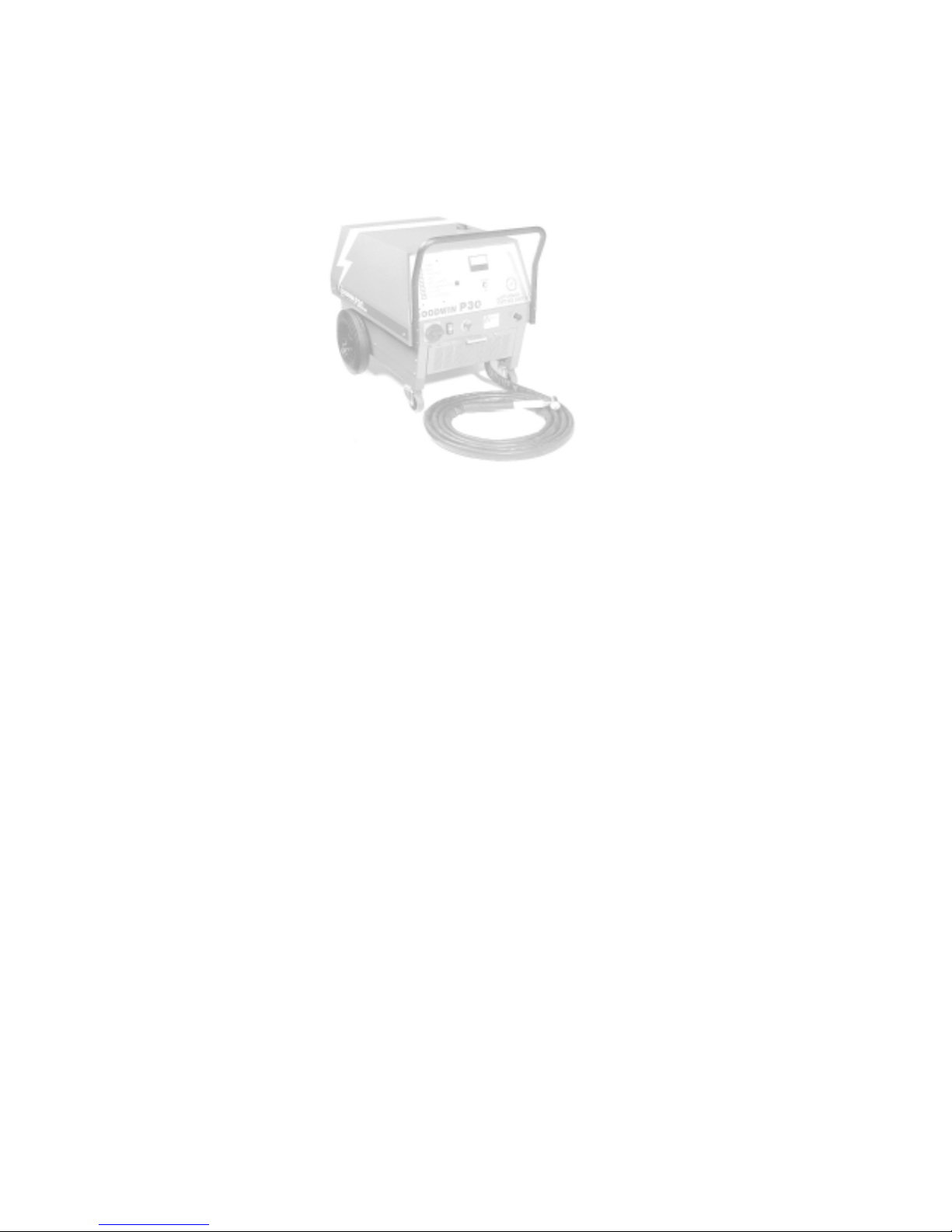
GOODWIN P30U
UNDERWATER
AIR PLASMA CUTTING SYSTEM
Page 2

Page 2 P30U Instruction Manual Revision : 1 1st December 2006
The Company reserves the right to make such changes to the design or specification of the
equipment as it shall see fit. The information contained in this manual is issued for the guidance of users
and does not form part of any contract. It is strongly recommended that all users and supervisors
familiarise themselves with the contents...
PRIOR TO COMMENCING USE OF THE SYSTEM
...and in particular, the section on safety precautions which should be used as a guide to safe
operation in accordance with the requirements of the relevant Health and Safety at W ork legislation.
GOODWIN AIR PLASMA LIMITED
KERNAN DRIVE
LOUGHBOROUGH
LEICESTERSHIRE
LE11 5JF
ENGLAND
Tel No. +44 (0)1509 237369
Fax No. +44 (0)1509 234942
Email. goodwinplasma@aol.com
Page 3

P30U Instruction Manual Revision : 1 1st December 2006 Page 3
Contents
1 ................................................................................................................................................. SAFETY 4
1.1................................................................................................................................................General 4
1. 2.................................................................................................................................. Safety Features 5
1. 3.................................................................................................................................... Warning Signs 5
1. 4 ................................................................................................ Packaging Handling and Transport 5
2 . ....................................................................... INTRODUCTION TO THE PLASMA PROCESS 6
3 . ................................................................................................................................ INSTALLATION 7
3. 1......................................................................................................................................Power Supply 7
3.2..........................................................................................................................Earth Requirements 7
3. 3 ........................................................................................................................ Phase Determination 8
4 . ..................................................................................... PLASMA AND TORCH CONNECTIONS 9
4. 1............................................. Connecting the Torch and Plasma Earth Lead to the Power Unit 9
4. 2........................................................................................................................ Control of theTorch 10
5 ...................................................................................................................................... OPERATION 11
5. 1 ............................................................................................................................ Machine Controls 11
5.1.1 ......................................................................................................... WARNING INDICATORS 13
5.2.......................................................................................................................Power Up Procedure 14
5. 3 ...........................................................................................................................Cutting Procedure 15
5.3.1. .................................................................................... STARTING AND FINISHING A CUT. 15
5.3.2. .............................................................................................. CUTTING WITH STAND OFF. 15
5.3.3. ..................................................................................................................... CUTTING SPEED. 16
5.3.4. ...................................... PIERCING THICKER MATERIALS WITH A HAND TORCH 17
5. 4 .............................................................................................................................. Troubleshooting 18
5.5............................................................................................................................ Consumable Life. 18
5.5.1. ..................................................................................................................... INTRINSIC LIFE. 18
5.5.2. ............................................................................................................................ ALIGNMENT. 18
5.5.3. .......................................................................................................... TRANSIENT DAMAGE. 18
5.5.4. ................................................................................................... OPERATIONAL DAMAGE. 19
5.5.5. ....................................................................................... ELECTRODE “NON-STARTING”. 19
5. 6 .................................................................................................................. Changing Consumables 20
5. 4 .............................................................................................................................. Troubleshooting 23
5.5............................................................................................................................ Consumable Life. 23
5.5.1. ..................................................................................................................... INTRINSIC LIFE. 23
5.5.2. ............................................................................................................................ ALIGNMENT. 23
5.5.3. .......................................................................................................... TRANSIENT DAMAGE. 23
5.5.4. ................................................................................................... OPERATIONAL DAMAGE. 24
5.5.5. ....................................................................................... ELECTRODE “NON-STARTING”. 24
6 . ......................................................................................................................... TECHNICAL DATA 25
6. 1 ........................................................................................................................................Power Unit 25
6.1.1. .............................................................................................................. ELECTRICAL INPUT 25
6.1.2. ........................................................................................................................ Electrical Output 25
6. 2........................................................................................................................ Torch and Hose Set 25
6.2.1 ........................................................................................................................... HAND TORCH 25
7 . ............................................................................................................ SERVICE INFORMATION 26
7. 1 ................................................................................................................................ The Power Unit 26
7.1.1. .......................................................................................................................... Circuit Diagram 27
7.1.2. ................................................................................................................ MACHINE LAYOUT 28
7.1.2. ................................................................................................ DIAGNOSTIC INDICATORS. 30
7. 2 ................................................................................................... The Torch and Hose Set Repair 31
7. 3 .................................................................................................................................... Maintenance 32
Page 4

Page 4 P30U Instruction Manual Revision : 1 1st December 2006
1. SAFETY
1.1 General
Before any cutting operations are started, the user must ensure that the installation and proposed
working methods comply with all relevant safety regulations, environmental and electricity standards.
The plasma arc produced at the torch head is a jet of high energy and is potentially dangerous. Users
unfamiliar with a plasma arc should seek basic training. Goodwin Air Plasma can offer comprehensive
training courses.
In addition, the following points are particularly important:
a) The mains connection must be properly grounded and the supply lines fitted with fuses or circuit
breakers of the specified rating. The mains cable must be properly secured and protected from possible
damage.
b) High voltage exists at the torch when power is applied and the pilot arc is struck (up to 350V), and
when the main arc is cutting (150-200V). Under no circumstances should anyone touch the nozzle with
power applied to the torch. All adjustments and replacement of parts should be done with the power unit
supply isolated. The standard torch should not be used in excessively wet conditions or if the torch or hose
set are damaged in any way.
Note that the PTU torch, its umbilical and associated extensions and connectors are designed to be used
underwater. The current specification is to a maximum of 30m, although it has been tested to a simulated
70m..
The electrical connectors are underwater mateable (to ocean depth) but in practice it is not advisable to
disconnect the coolant and air lines underwater, so this would normally be done on the surface.
c) The mains supply should be isolated from the unit AT THE SUPPLY before removing any panels
from the unit. Only authorised service personnel should remove panels.
d) Keep the work area clear of all inflammable materials. Ensure that any material ejected from the cut
is not a hazard to the operator or to others.
e) Protection is necessary against ultraviolet radiation emitted from the arc. A helmet or shield with
shade glass is recommended. Note, however, that the plasma arc does not usually need to be observed
closely, if at all. It is more often necessary to be able to see the material surrounding the cut, so a lighter
shade than that used for welding will probably be required. Furthermore, when cutting underwater, the UV
is absorbed by the water to a considerable degree. Wear gloves and adequate protective clothing where
appropriate. Adequate screening should be arranged to protect others in the vicinity or passing by in a similar
manner to that required for arc welding operations.
f) Adequate ventilation or fume extraction to remove the cutting fume and dust is required at all times
around any plasma cutting operation.
g) The wheels on the unit are meant for ease of movement around the work place and should not be
used over rough surfaces nor at excessive speeds.
h) The plasma power unit should be positioned on stable level ground and if necessary secured against
any unwanted movement.
i ) The operation of this equipment and the plasma cutting process can result in noise levels that could be
harmful. When cutting underwater the noise level from the arc is substantially reduced and does not represent
a risk to the diver. The employer should undertake a noise assessment to monitor compliance with relevant
legislation.
j) Material to be cut should be supported in such a way that any material cut from the work piece will
not be a hazard and fall onto the user, the equipment, or others in the vicinity.
k) Care should be taken when manoeuvring the hose set with either a hand held torch or one connected
to a robotic device, that it does not snag on objects or other equipment which may result in damage to the
hose set, or topple the objects or equipment. Hose sets that are subject to excessive mechanical tension may
result in damage to the hose set connections at the machine, the torch, or the hose set components themselves.
Page 5
P30U Instruction Manual Revision : 1 1st December 2006 Page 5
1.2 Safety Features
The plasma unit includes the following features for the safety of the operator:
* The body of the plasma torch is earthed.
* The continuity of the torch earth and the voltage on the body is monitored.
* Cutting current flowing in the supply earth is monitored.
* The voltage on the torch nozzle is monitored.
* In the event of a faulty condition of the above, the machine will switch off power to the
torch.
The emergency stop procedure is to hit the red emergency stop button located on the lower front
control panel.
A tool (10mm spanner) is required to remove the canopy for access to the internal components. Under
no circumstances should the canopy be removed whilst the mains supply is still connected. Only suitably
trained and authorised personnel should remove the canopy .
1.4 Packaging Handling and Transport
Should the plasma unit need to be shipped, we recommend re-use of the original packing crate. Also:-
a) That the hose set be disconnected to prevent any damage to the hose set / plasma connections.
b) That the control panel is adequately protected against potential damage.
c) Any lifting should be done using the eyebolt located in the top of the canopy together with certified
lifting equipment (not supplied). Precautions should be taken to prevent rotation about the eyebolt.
d) The plasma unit should be shipped and stored in the upright position to avoid any heavy internal
components breaking free from their mountings.
e) Storage should be undercover, preferably in a clean dry environment.
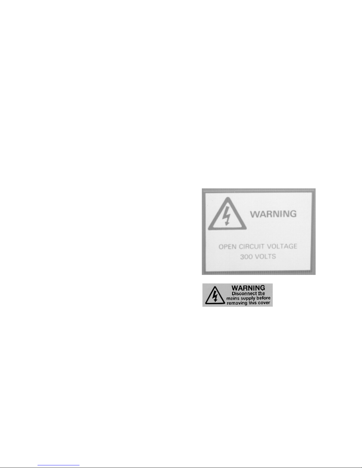
1.3 W arning Signs
The location of the warning signs fitted to the plasma
unit are:
a) At the front of the machine W arning Open Circuit V oltage 300 volts.
b) At each rear lower corner of the canopy -
W arning Disconnect the Mains Supply.....
These should be maintained in a legible condition.
Page 6

Page 6 P30U Instruction Manual Revision : 1 1st December 2006
2. INTRODUCTION TO THE PLASMA PROCESS
The plasma process is created by passing a stream of clean air, provided by an oil free compressor ,
through a NOZZLE in the torch. The air stream is ionised by a PILOT ARC, initiated by a HIGH
FREQUENCY unit (HF Unit) which passes from the ELECTRODE to the nozzle when the torch is
activated. When the PILOT ARC is brought close to the work piece, MAIN ARC is TRANSFERRED
to the work piece as a jet of high energy which rapidly melts any metal with which it makes contact,
providing fast cutting, low residual heat input, and low material distortion.
The electrode and nozzle are cooled by the air and a recirculating water cooling system, and as the air is
passed through the nozzle it is caused to swirl around the arc by a SWIRL BUSH to aid stability of the
arc.
The HF unit operates automatically to establish an arc when power is applied to the torch and it ceases
to operate when the pilot or main arc is established.
Page 7
P30U Instruction Manual Revision : 1 1st December 2006 Page 7
3. INSTALLATION
May be carried out by a competent electrician. No specialist tools are required.
3.1 Power Supply
The power unit is provided with a length of flexible cable which must be connected to a 3-phase
and earth electrical supply . The supply should be fitted with fuses or circuit breakers of appropriate
rating and a means of isolating the power unit from the supply should be provided. A plug should be
fitted if appropriate. The machine is phase/rotation sensitive.
The power unit has power factor correction capacitors fitted as standard. It must be noted that
when the unit derives its power from a generator, the power factor correction may disturb the generators’ automatic voltage control. If recommended by Goodwin Air Plasma, the power factor correction
circuit can be disconnected however this will increase the input current demand. The P30U has automatic switching of the power factor correction so that it only operates whilst cutting, so it is unlikely to
cause this problem. This may be fitted as an option to other variants.
Refer to the rating plate on the machine and Technical Data section 6.1.1. for the correct voltage
and current r equirements.
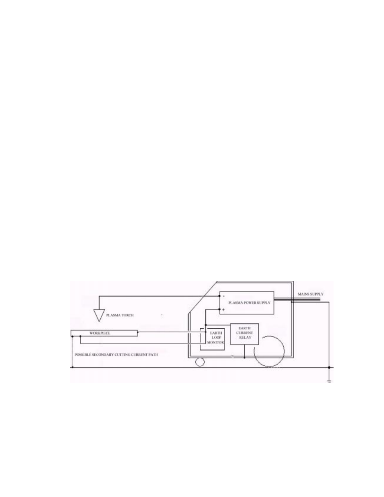
3.2 Earth Requirements
The installation should ideally be arranged such that the only path to earth (or ground) from the work
piece is by way of the plasma earth lead connected to the front of the machine.
Where the material to be cut forms part of the structure which is earthed or grounded to the mains
electrical supply system, then the cutting current could flow through that route rather than the plasma
earth lead to the machine. Always ensure that there is a good connection between the work piece and
the machine via the plasma earth lead as a poor connection will cause excessive current in the mains
supply earth which will create a current trip fault condition (see section 7.4 fault finding).
Note that the Earth Loop Monitor system used in the underwater machine will ensure that a good
connection is made.
In installations where it is not possible to avoid earth current trips, even though a good cutting
current earth path has been ensured, it will be necessary to check that the alternative mains earth paths
are substantial enough to carry higher currents than the current trip setting of 30amps (*) without causing
damage, as where the cutting earth is not connected to the work piece at all, this would be the full cutting
current. If the earth paths are not substantial they must be uprated or re-routed to avoid the possibility of
damage. Once the necessary checks and precautions have been taken, the earth current trip circuit may
be disabled by means of the switch on the Earth Current Relay (ECR) located inside the power unit.
*Since the workpiece will often be substantially connected to the supply earth in underwater work,
and significant currents must be allowed to flow in seawater to the torch and umbilical earth, a less
sensitive earth current relay is used. The standard machine sensitivity is 10A. This should avoid most
cases of nuisance tripping, and the need to disable the ECR.
Page 8
Page 8 P30U Instruction Manual Revision : 1 1st December 2006
3.3 Phase Determination
Connect the torch to the machine (see section 4).
Fill the water system with distilled water.
Note.To avoid damaging the water pump the machine should not be run without water in the
system. Also, the machine should not be run for mor e than a few seconds without a torch connected
to the machine. It may be necessary to eliminate air from the system, and vent the de-ionizing filter,
to establish a proper flow.
Switch on the machine by rotating the main isolator and pressing the on/off button ensuring the
emergency stop switch is unlatched.
Correct phase connection is determined by checking that the cooling air flowing thr ough the power
unit is from the fr ont panel to the r ear of machine. If this condition is not corr ect, change two of the
three phase connections at the power supply and check again. The fan rotation, when viewed from
the front of the machine, is anti-clockwise.
If there is any doubt regarding installation, consult your distributor or Goodwin Air
Plasma.
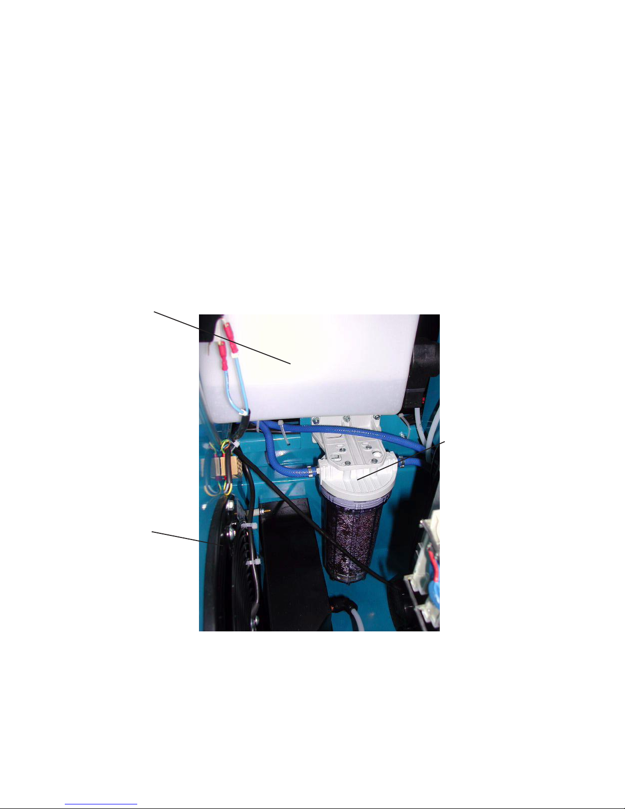
Fan Rotation AntiClockwise
W ater T ank
De-ionizing
Filter
Page 9
P30U Instruction Manual Revision : 1 1st December 2006 Page 9
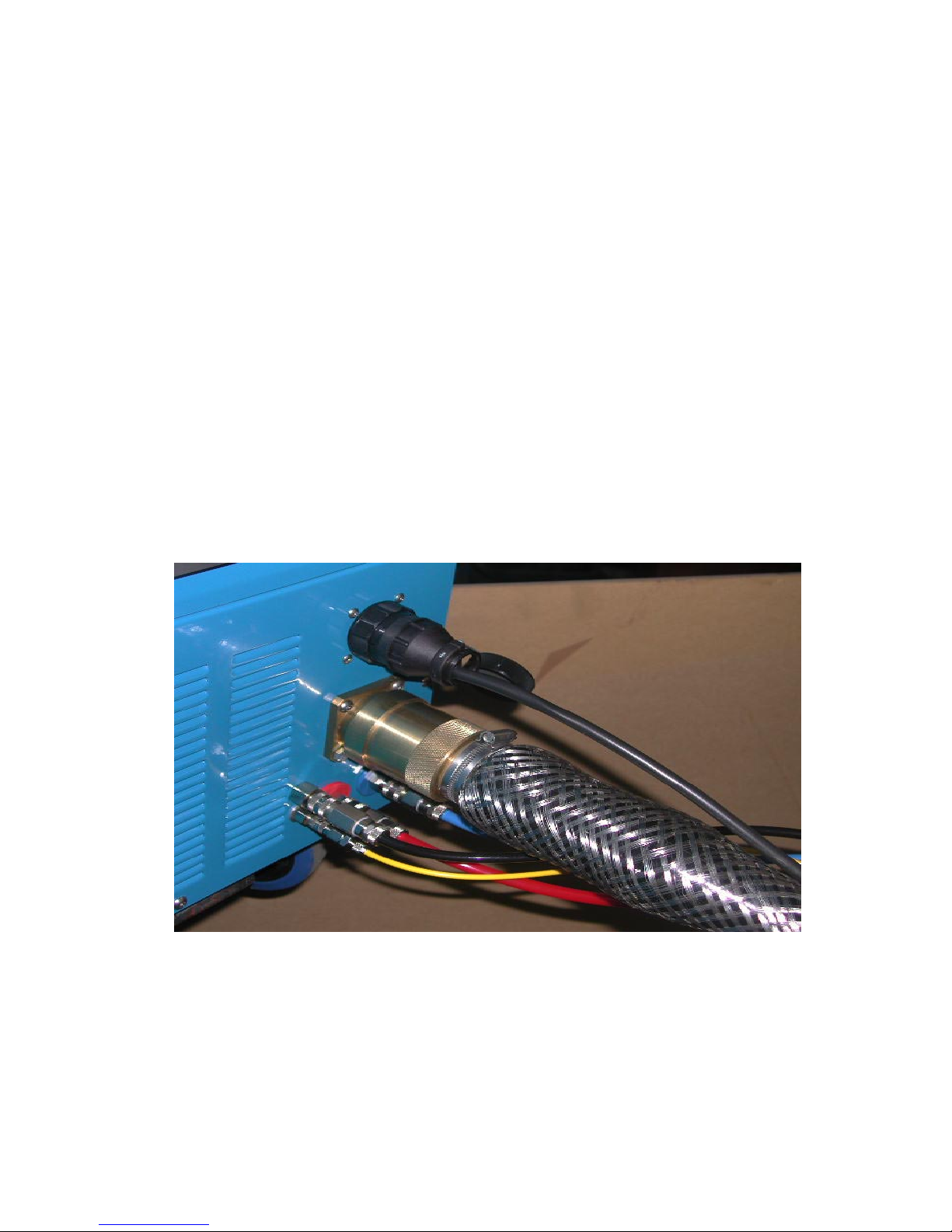
4 . PLASMA AND TORCH CONNECTIONS
4. 1 Connecting the Torch and Plasma Earth Lead to the Power Unit
Note. Do not run the power unit without the torch connected.
The connections to the power unit are located at the front of the unit.
The PTU torch and umbilical extensions use a specially designed electrical connector for the power,
safety earth, pilot arc, and all other electrical connections. There is a central pin that carries the
power, a pin for the pilot arc connection and 5 smaller pins for safety monitoring and the diver’s
control switch. The safety earth is made thr ough the locking sleeve. There ar e four hose connectors,
filled with quick acting connectors.
the blue hose is the cooling water to the torch;
the red hose is the cooling water return from the torch
the black hose carries the plasma air
the yellow hose is a “pneumo” connection to allow the plasma air pressure to
automatically track the working depth
The water connections are not polarised but it is advisable to follow the colour coding.
These connectors are found on the machine front panel and replicated at the socket end of the extension umbilicals.
The supervisor’s remote control panel connects to a multiway socket above the torch connectors.
(Note that this is an “analogue” lamp, therefor e it may be illuminated but not at full brightness,
and the indicator (which is “digital”) on the front panel and the supervisors panel still fail to
light because of a poor connection).
When first switching on, allow enough time for the water to circulate through the system. T op up the
header tank as required. Use only distilled or de-ionised water. (See section 7.1 regarding use of
methanol in freezing conditions).
The two earth connectors (insert and twist clockwise to lock) are located on the left hand side of
the front panel. An indicator lamp indicates when an earth loop has been successfully made.
Page 10

Page 10 P30U Instruction Manual Revision : 1 1st December 2006
4.2 Control of theTorch
Note that the torch has a switch for use by the diver, but that this is used in conjunction with the
supervisors panel and a communications procedure to energise the torch. The torch will de-energise if
the diver’s switch is released at any time.
Note that it is good practice to leave the power unit running at all times when the torch
is underwater to prevent the torch and air hose filling with water.
Cooling air will flow through the torch at all times when the machine is switched on.
Page 11

P30U Instruction Manual Revision : 1 1st December 2006 Page 11
WARNING
INDICATORS
MAIN ISOLA TOR
ON / OFF BUTTONS
EMERGENCY STOP
OUTPUT ON LAMP
AIR PRESSURE GAUGE
AIR REGULA TOR
RESET BUTTON VOLTMETER
5 OPERA TION
5.1 Machine Controls
The front panel of the machine provides a range of displays and control gear to ensure correct operation
ON / OFF BUTTONS
Switches auxiliary circuits on and off. ie Compressor, water pump, cooling fan and control circuits
MAIN ISOLA TOR
Isolates machine from mains supply . It may be padlocked in the off position.
EMERGENCY STOP
Switches machine off. The switch latches mechanically and must be rotated to release.
Page 12

Page 12 P30U Instruction Manual Revision : 1 1st December 2006
Hose Connections
See section 4. Connecting the torch to the power unit.
Voltmeter
Indicates the arc voltage.
T ypical values would be: Power applied to torch but no arc 300v (actually off-scale: up to 350V)
For Pilot Arc 250 to 300 volts
For Main Arc 150 to 200 volts
(V oltage is affected by supply voltage, cutting depth, cutting speed and material thickness)
Output ON LAMP
Indicates that power is applied to the torch.
Reset Button
Resets earth current, earth safety , and water warning circuits.
Air Pressure Gauge
Displays the back pressure in the system during the pilot arc and cutting modes
T ypical values would be: For Pilot Arc 0.7 to 2.2 bar (10 to 30 psi)
For Main Arc 2.4 to 3.4 bar (35 to 50 psi)
Note that the air regulator tracks the working depth, therefore the pressure gauge shows this operating
pressure plus the working depth (1 bar = 10m = 32 ft)
Tracking Air Regulator
Sets the air flow through the torch to give a stable pilot arc and adjusts to allow for the working depth.
Note that essential indicators on the front panel, and the reset button, are replicated on
the supervisor’s panel, and it is normally only necessary to switch the machine on or off
at the power unit.
Note that the supervisor’s panel and the dual earth system must be used before it is
possible to energise the torch.
It is possible to use the machine in a conventional mode for dry cutting in the workshop (ie single
earth and control by torch switch) by use of a special bypass plug fitted to the supervisor’s remote
control socket. If supplied this should not normally be kept with the machine to prevent use in
inappropriate circumstances. It should never be used when operating underwater
Page 13

P30U Instruction Manual Revision : 1 1st December 2006 Page 13
POWER
READY
TEMPERATURE
W ATER FLOW
EARTH CURRENT
EARTH SAFETY
PILOT TRIP
EARTH LOOP MONITOR
POWER INDICA TOR Indicates that power is available to the system control circuit.
READY INDICATOR Indicates system interlocks are operational and the machine is ready to cut
TEMPERA TURE INDICATOR Indicates that the rectifier or transformer temperature is too high.
WA TER INDICATOR Indicates insufficient water flow in the torch.
EAR TH CURRENT INDICA T OR Indicates excessive currents in the supply earth (see section 3.2).
EARTH SAFETY INDICA TOR Indicates a break in the earth connection to the torch or a voltage in excess of 10 volts to the torch body .
PILOT TRIP INDICATOR Indicates the pilot arc has excessive current, due to consumable condition or insufficient air flow .
EARTH LOOP ENABLED This shows that the dual earths are properly connected to the workpiece which will enable the diver's
switch
5.1.1 W ARNING INDICA T ORS
See section 7.1.2 Displays and Controls for more details.
Page 14

Page 14 P30U Instruction Manual Revision : 1 1st December 2006
5.2 Power Up Procedure
NOTE.
As this plasma power unit does not have a voltage stablised power supply , a fluctuation in the input voltage
will directly affect the output current. This may not be noticeable if the input voltage rises slightly above the
norm as it will provide more power for cutting. If the rise is excessive, consumable life may suffer . However,
when the input voltage falls, the output power also falls, affecting both the pilot arc and main arc. In these
circumstances it will be necessary to adjust the air pressure regulator to reduce the airflow to obtain a
stable pilot arc, and readjust it when the mains voltage returns to normal.
Having completed the mains and cutting earth wiring, connected the torch and checked the fan
rotation, and connected the supervisors panel, the machine is ready for use.
Switch the machine on and after allowing time for the water to circulate through the torch, press the
reset button on the front panel or supervisors panel. The red indicators should go out and the ready light
will illuminate. Note that the supervisors panel will always need to be reset, even if the machine has been
reset on the front panel.
T o ascertain the absence of air leaks, the air regulator should be wound fully clockwise and the
pressure gauge should indicate a back pressure in excess of 3 bar.
It is now necessary to adjust the air pressure to give the highest possible reading consistent with good
arc starting and a stable pilot arc, this should be at least 0.7 bar. Switch on the torch with the nozzle well
clear of any workpiece, person or equipment, and re-adjust the air pressure until it is at maximum or the
pilot arc becomes unstable (very noisy , misfire, and the voltmeter showing 300 volts). At this point reduce
the pressure to restore stability (arc less noisy , stable arc, and the volt meter showing 250/300 volts).
Always maintain as high an air pressure as possible for pilot arc as this gives the best consumable life.
The output neon is “on” and the voltmeter reads between 250 vdc and 300 vdc at this stage.
The machine is now setup and is now ready to be used. Before starting a cut please see section 1 for
safety information and then section 5.3 for cutting procedure. The correct procedure for cutting underwater
is considered more fully in the Supervisors Panel Instructions
Page 15

P30U Instruction Manual Revision : 1 1st December 2006 Page 15
IMPORTANT
Under normal cutting conditions the torch is designed to
operate with a STAND OFF of about 6 mm. This is the
distance between the end of the nozzle and the work piece.
Underwater this will probably be reduced to 2-3mm, say ,
by modifying the Guide Ring, if used.
Where the work piece is rusty , scaly, or with thick sections
of steel or aluminium etc., a build up of dross on the top of
the work piece may occur which will cause damage to the
nozzle. In these conditions, the stand off distance should be
increased slightly .
A guide ring is avalable to assist the operator in maintaining
the desired stand off height. This can also be used against a
straight edge to maintain a straight cut.
5.3.2.Cutting With Stand Off.
5.3 Cutting
Procedure
Where possible it is better to start a cut at a plate edge or hole because the piercing process reduces
consumable life.
Cuts can be started by either initiating the pilot arc and moving the torch into the proximity of the work
piece, or by positioning the torch over the edge of the work piece and starting the pilot arc. Underwater,
and especially at depth, it may be necessary to always start very close to the workpiece.
Materials with a capacity to absorb heat energy , especially thicker sections, require more care and technique
when starting a cut. In these cases the cut will appear slow to start and pierce through the material. Once
a cut is established then cutting speeds may be increased.
Cutting can be stopped either by releasing the torch switch, or at the supervisors panel, or in an emergency
by switching off the power unit. It will stop cutting if moved away from the workpiece, but will then reestablish a pilot arc. This is not recommended practice for underwater cutting.
5.3.1.Starting and Finishing a Cut.
If the arc should “flare”, be coloured green, or emit any unusual noise, it is essential that the torch be
immediately switched off and the condition of the consumables checked. This usually indicates that the
consumables are damaged or reached the end of their useful life. Continuing to try and cut under these
conditions may result in damage extending beyond the consumables to other parts of the torch.
Page 16

Page 16 P30U Instruction Manual Revision : 1 1st December 2006
5.3.3. Cutting Speed.
Best results are usually obtained by cutting at the optimum cutting speed.
OPTIMUM CUTTING SPEED
Correct cutting speed is judged by experience from
observing the angle at which the cut material leaves the
lower edge of the plate, either by observing the ejected
material or by studying the surface of a cut after completing a test cut. The drag back of the arc is aproximately 30
degrees.
CUTTING TOO SLOW
Arc appears to blow straight through the material.
Excessive dross may accumulate on the underside of the
material.
CUTTING TOO F AST
Arc fails to pierce the material. Blow back of dross will
damage the nozzle.
MAXIMUM CUTTING SPEED
Drag back of the arc is around 45°, but cut quality will
deteriorate.
Page 17

P30U Instruction Manual Revision : 1 1st December 2006 Page 17
5.3.4. Piercing Thicker Materials with a Hand T orch
Piercing will cause cut material to be ejected upwards which can be dangerous, and has a risk of damaging
the torch nozzle. This problem is worsened as material thickness increases because it takes longer to
pierce. If it is necessary to pierce, then it is best done by angling the torch and gradually bringing it upright
as piercing is completed.
Initiate the pilot arc and lay the torch over at approximately 60º
Begin twisting the torch slowly towards a vertical position taking
care to avoid ejected material from hitting the nozzle. At the
same time, the torch should be moved a small distance along the
work piece.
As piercing completes, the nozzle can be brought to vertical and
cutting can continue.
If the torch is pivoted about the nozzle there is a risk of material
being blown back onto the nozzle which will cause damage to the
nozzle or even to the torch itself.
*
Imaginary pivot point. X
X
X
X
X
Page 18

Page 18 P30U Instruction Manual Revision : 1 1st December 2006
Bevel is more noticeable on thinner sections and is more pronounced on the left hand side of a cut. It is
due to the clockwise swirling of the air induced by the swirl bush in the electrode assembly . Bevel edges
can be desirable as an aid to weld preparation, however it can be virtually eliminated by reducing the
cutting speed but at the expense of accumulated dross. For minimum bevel cut clockwise around a
component and anticlockwise in a hole.
5.5.Consumable Life.
A good consumable life is the single most important factor in achieving optimum cutting economics of
any plasma cutting unit. This life is dependent on the intrinsic life of the consumables, correct alignment
and the incidence of transient and operational damage.
5.5.1.Intrinsic Life.
The intrinsic life of the consumables is determined by the rate at which they are eroded by the arc
process. This erosion rate is however low , and in practice, the life is limited by other factors. The insert
in the centre will be eroded slightly each time the arc is struck eventually creating a visible crater . The
crater can be more than 2mm deep before the electrode is considered to be expired.
5.5.2.Alignment.
The alignment and construction of the Goodwin Air Plasma T orch is such that problems of grinding and
adjusting electrodes do not occur. With reasonable care taken in fitting the consumables, alignment
problems should not arise.
5.5.3.Transient Damage.
On starting directly onto main arc, it is occasionally possible to erode some of the copper from the
electrode before the arc settles onto the insert material. This generates a crater in the electrode and the
insert burns back to become flush. Consumable life is thus reduced if there is a high number of starts
relative to the total cutting time.
Cutting speed too slow . Torch consumables worn or damaged. Insuf ficient
air flow .
Damaged torch consumables. Nozzle blocked by dross or too close to
work piece. Insufficient air flow .
Nozzle orifice damaged. Electrode eroded “off centre”. Consumables
wrongly fitted.
Speed too high. Stand off too high. Arc not straight - consumables damaged
or misaligned.
Excessive dross on lower
edge of cut.
Double arcing.
Main arc not square to
work piece.
Excessive bevel or rounded
cut surface.
5.4
T roubleshooting
Page 19

P30U Instruction Manual Revision : 1 1st December 2006 Page 19
5.5.4. Operational Damage.
This is the most likely cause of limited consumable life. Since the arc is quite capable of cutting copper,
anything which causes the arc to deviate from the centre of the nozzle will result in damage to the orifice.
In extreme cases the arc passes not through the orifice but from the electrode to the nozzle and from the
nozzle to the work piece - DOUBLE ARCING, causing the rapid erosion of copper from both
electrode and nozzle.
The most common cause of these problems is from ejected cut material entering the orifice particularly
when piercing or obstructing the nozzle with the work piece.
It is best to operate within the maximum speed capabilities of the machine and avoid unnecessary
piercing or stop-start cutting whenever possible.
5.5.5.Electrode “non-starting”.
ILLUSTRA TION T O SHOW ELECTRODE DAMAGE
NEW ELECTRODE
USED ELECTRODE
WORN OUT EXPIRED
Occasionally , it may happen that it is difficult to start the pilot arc. This happens when the oxidized material
from the electrode insert is deposited over the surface of the copper electrode and inside the nozzle.
Starting can be improved by cleaning or scratching the surface of the electrode with a wire brush or sharp
implement. Always switch of f the power unit before removing the nozzle for this purpose. Once a “nonstarting” electrode has been used a few times, starting usually improves.
It is not good practice to fire the pilot arc continually in mid-air without striking the cutting arc as this
oxidizes the surface of the electrode and leads to “non-starting” problems.
Since cutting usually improves a non-starting electrode, it may be desirable to use a piece of scrap material
and start the main arc immediately by positioning the torch close to the material before switching on. Once
started, continue to cut for as long as possible before trying to re-initiate the pilot arc.
W e have found that on some occasions when cutting under water, the electrode is rapidly covered in a
heavy black deposit that causes problems identical to “electrode non-starting”. W e are not yet sure why
this should happen, although it has been suggested that atmospheric humidity , and consequently excessive
water in the compressed air, could be responsible. The air supply is fitted with a drying system:
The practical “cure” is the same – to scratch the copper surface of the electrode, and to this end a special
tool is supplied in the tool kit to enable this to be done by the diver underwater, without removing the
nozzle. Note that careful communication procedures should be used when this is done, to ensure
the supervisor does not “make it hot” if the diver should inadvertently touch the torch switch.
Page 20

Page 20 P30U Instruction Manual Revision : 1 1st December 2006
5.6 Changing Consumables
The Goodwin Underwater PTU torch carries a number of elements known as the CONSUMABLES
which are eroded during the cutting process. They consist of:
a) Nozzle.
b) Electrode Assembly comprising:
Electrode
Swirl Bush
O ring
Other parts that may be damaged and replaced by the user are:
Front Cap
Front Cap Retaining and Sealing Rings
Front Insulator
Contact Tube.
TORCH HEAD
FRONT CAP RET AINING RING
FRONT INSULA TOR
FRONT CAP SEAL
CONT ACT TUBE
ELECTRODE ASSEMBL Y
NOZZLE
FRONT CAP
Page 21

P30U Instruction Manual Revision : 1 1st December 2006 Page 21
Note that changing consumables should always be done by recovering the torch to the surface,
and switching the power unit off.
The electrode and nozzle are the same as the standard torch, although two different sizes
of nozzle may be used depending on the nature of the work and the depth.
As well as a retaining ring for the front cap there is a sealing ring fitted in the front
insulator that engages with the underwater front cap.
(For dry cutting the standard front cap may be used)
Silicone compound should be applied liberally around the nozzle and this seal, but not fill the space
between the seal and the front cap retaining ring as it may be caught between the two seals and
prevent fitting of the front cap.
The front insulator may be replaced if damaged using the special tool provided. This is an operation
that requires considerable care, as it is necessary to engage a fine thread in the plastic component.
The front insulator carries a second (identical) 0-ring that should be lightly coated with silicone
compound prior to fitting. It is then necessary to engage the fine thread on the outside of the front
insulator with that on the inside of the nozzle holder. Once sure that it is properly engaged, the
special tool engages with two small slots to screw the insulator fully home. Do not use undue
force!
Removal of a damaged insulator may require use of pliers or similar, if the slots have been damaged.
The contact tube can also be replaced if necessary , as on the standard torch, with the 1/8” Allen
Key
Page 22

Page 22 P30U Instruction Manual Revision : 1 1st December 2006
T o renew the consumables, the following procedure should be adopted, remembering that care and
cleanliness are of the utmost importance.
1. Recover the torch to the surface.
2. Switch the machine off at the mains supply or Main Isolator.
2. Remove the Front Cap. The cap is a push fit over the O ring seated in a groove in the outer diameter
of the T orch Body and engages with a sealing
ring on the Front Insulator.
3. Unscrew the Nozzle with the special tool
supplied. (See illustration left).
4. Check the condition of the Electrode
Assembly . If it is to be removed, grip the
Electrode Assembly with the special Electrode
Pliers provided, and pull firmly out from the
torch body . (See illustration right).
5. Press a new Electrode Assembly carefully but firmly over the contact tube until it is fully home and
central. Use the handle of the Nozzle T ool which has been prepared for this purpose. THIS IS
VERY IMPOR T ANT ! If the Electrode is not pressed fully home onto the Contact T ube, the Swirl
Bush may be partly crushed by the Nozzle, and will interfere with the airflow .
6. Carefully screw the Nozzle into the T orch Head using the special tool until fully home. DO NOT
OVER TIGHTEN.
7. Apply a liberal quantity of Silicone Grease around the front of the torch, especially to fill the space
between the nozzle, front cap and sealing ring.
8. Refit the push fit Front Cap. Apply additional grease over the outside of the front cap. The grease will
provide a first line of defence against material blown back from the cutting process.
Remember that cleanliness and care must be taken when fitting consumables. Do not allow dirt to
obstruct the threaded parts of the torch. T ake care when engaging threaded parts not to damage the
thread.
CONT ACT TUBE REPLACEMENT.
Should the Contact Tube need changing, it is removed by inserting the 1/8" allen key supplied into the
centre and unscrewing. Replacement is the reverse of removal but it is important not to over tighten
as this may cause subsequent electrode fitment to be off centre, producing bevel cuts.
Page 23

P30U Instruction Manual Revision : 1 1st December 2006 Page 23
6. TECHNICAL DATA
6.1 Power Unit
6.1.1.Electrical Input
Input is via 3 core and earth flexible: 4 x 16mm2 3 metre length standard.
Machines are available for the following 3 phase supplies:
Note. When the power unit is connected to a generator it may be necessary to disconnect the power
factor correction capacitors in the power unit if they disturb the generator's automatic voltage control. This
does however increase the demand at full power.
With PF Without PF
Input V oltage Correction Correction
380v 50Hz 75 amp 106 amp
415v 50Hz 70 amp 98 amp
460v 60Hz 70 amp 98 amp
Other voltages and frequencies available to order
6.1.2. Electrical Output
Open circuit voltage 330-345V dc
Typical arc voltage 150-200V dc
Main arc power 36kW
Pilot arc current 15 - 20 amps nominal
Duty cycle 100%
6.1.3 Miscellaneous
Compressor type Oil f ree twi n cyli nder.
W ater pump type Regenerative type.
W ater capacity 10 litre (aprox. dependant on hose length)
distilled or deionised water
6.1.4. Dimensions
Length 1200mm (48") inc wheels and handle.
Width 800mm (32") "
Height 800mm (32") "
W eight 290 kg ( 640 lb)
6.2 Torch and Hose Set
6.2.1 Hand Torch
T orch body diameter 40mm
T orch head weight 1.0 kg
Effective weight (inc. hose set) 1.5 kg
Hose set lengths available 10m, 15m, 20m, 30m, longer with 30m Extensions.
Hose set water capacity 0.6 litres per 10m length
Page 24

Page 24 P30U Instruction Manual Revision : 1 1st December 2006
7. SERVICE INFORMATION
7.1 The Power Unit
The power is carried to the torch electrode by a cable within the umbilical.
Pilot arc connection to the nozzle is made via a current limiting resistor and switching circuit in the rear
of the machine and a coaxial cable in the umbilical. The pilot arc connection to the nozzle is
disconnected on main arc transfer. The HF arc ignition is fully automatic in operation, being powered
from the torch power lines.
The compressor and cooling fan are the only “phase sensitive” components and it is essential to ensure that
their direction of rotation is correct according to the installation instructions (see section 3).
These components and the water pump are protected by thermal / magnetic overload switches. If an
overload should operate, after establishing the reason for the trip (e.g. missing supply phase). It can be
reset by first removing the machine cover then pressing the manual reset button on the overload unit
situated behind the instrument panel.
The transformer, air and water radiators, and the pilot arc resistor , are cooled by an electric fan. A temperature
sensing interlock inside the transformer windings protects the system against thermal overload should the
cooling fail or be obstructed hence it is essential to ensure adequate air circulation around the machine at all
times. The rectifier is cooled by a small fan, and has thermal overload and varistor diode protection.
The air compressor is of the oil free, maintenance free, twin piston type fitted with two cleanable/
replaceable inlet filters contained in black screw-in housings. The air from the compressor is first passed
through a cooling radiator and then a coalescing filter to dry it. This has an automatic drain.
The high pressure water pump supplies cooling water to the torch through quick release, self sealing
couplings so that the torch can be disconnected without the loss of water from the system. There is an
interlocked flow sensor on the return line which shuts down the arc if the water flow should be restricted.
The water cooling circuit is fitted with a de-ionising canister. This is principally in case of contamination of
the coolant (de-ionised water) by seawater or similar, for instance should the pipes become disconnected
underwater . Should the coolant become excessively conductive it will be necessary to change the deionising cartridge. When the cooling system has been empty it may be necessary to vent the canister of air .
This is done either with a vent valve on the top of the unit, when fitted, or by unscrewing the cartridge
housing slightly , until the water level rises to the top.
The header tank must be kept full of distilled water at all times. If site conditions dictate that antifreeze
should be used, then up to 33% METHANOL may be added.
NOTE. Ethylene glycol or automotive type antifreeze fluids MUST NOT BE USED, as they will cause
rapid corrosion of the torch.
There is an Earth Loop Monitor device which passes an alternating current around the loop formed by the
dual earth connections. This is also fitted with an ammeter shunt to allow the Supervisors Panel to display
cutting current. An additional loom connects between this and other additional features, and the standard
machine loom and the 24way socket to the Supervisors Panel.
Whenever any of the interlocks come into operation the appropriate warning light on the front panel will
indicate to assist in the diagnosis of the problem.
Page 25

P30U Instruction Manual Revision : 1 1st December 2006 Page 25
7.1.1. Circuit Diagram
Page 26

Page 26 P30U Instruction Manual Revision : 1 1st December 2006
7.1.2. Machine Layout
18
19 16
20
9
4
6
7
5
10
3
11
29
15
12
14
13
27
28
17
8
Page 27

P30U Instruction Manual Revision : 1 1st December 2006 Page 27
PARTS LIST
1 ................................................... Volt Meter
2 ............................................... Main Isolator
3 ........................... Motor Starter Compressor
4 ........................................ Motor Starter Fan
5 .......................... Motor Starter Water Pump
6 ...................................... Control Transformer
7....................................... Compressor Filters
8 ........................................................ Diodes
9 ...................................................... H F Box
10 .......................................... Aux Contactor
11.......................................... Main Contactor
12 ....................................... Control P C Board
13 ..................................... Arc Current Relay
14 ................................... Earth Current Relay
15 ...................................................... Fan
16 ...................................... Main Transformer
17 .......................................... Water Tank / Cap
18 ................................Water Pressure Switch
19 .................................... Radiator Assembly
20 ..................................... Pilot Arc Resistor
21 ..................................... Air Pressure gauge
22 ................................................Output Neon
23 ..................................... Air Pressure Regulator
24......................................... Stop/Start Switch
25................................ Emergancy Stop Switch
26............................................... Reset Switch
27................................................Water Pump
28 ................................................ Compressor
29 ........................................... Solonoid Valve
(Not Shown)................................ Dix Connector
(Not Shown). Power Factor Correction Capacitor
(NS) ..(Water fitting, Return) Mini Check Unit Long
(NS) .....(Water fitting, Feed) Mini Check Unit Short
PART NUMBERS
24
23
2
26
25
1
22
21
PX52MV300S
PX50IS99F
PX50CM025
PX50CM010
PX50CM016
PX56A200
PX57CXT01
PX54S0029
PX68MFI0870
PX50CA09
PX50CA80
PX55C10782A
PX68MF10323
PX68MF10565
PX57FA300
PX56M30+VOLTAGE
PX63T10833/PX63M004
PX50SA01
TO ORDER
PX54R0067
PX28100G
PX52BN240A12
PX29R08
PX50SP00Z
PX50SP001
PX50SP01
PX57W500
PX57C400
PX29VS99
PX4201RD300S
PX54C0038
PX29V01
PX29V10829
Page 28

Page 28 P30U Instruction Manual Revision : 1 1st December 2006
OUTPUT ON LAMP
Indicates that power is applied to the torch.
POWER INDICA TOR
Indicates that 12V power is available to the system control circuit.
READY INDICATOR
Indicates that all system interlocks including the access door are operational and that the machine is
ready to operate.
TEMPERA TURE INDICA T OR
Indicates that the rectifier heatsink and / or main transformer temperature is too high. Cutting operations
will immediately stop. Leave the machine running to allow the fan to cool the transformer. Systems will
automatically reset when the temperature drops.
WA TER INDICATOR
Indicates no water in the system, a water leak, torch blockage, low pump supply pressure or incorrect
motor/fan rotation. When water flow is restored, the system will reset automatically .
EAR TH CURRENT INDICA T OR
Indicates the main arc cutting current is flowing in a secondary path. System will stop until it is reset
when the torch switch is released. (See section 3.2 for cutting earth requirements).
EARTH SAFETY INDICA TOR
Indicates a break in the earth connection to the torch or a voltage in excess of 10 volts to the torch
body . This indicator will also illuminate as a self test when the machine is switched, on Depressing the
RESET button will reset the system provided the fault is rectified. This can also be reset on the
Supervisors Panel, which must be seperately reset in any case.
PILOT TRIP INDICA TOR
Indicates the pilot arc has excessive current. The circuit will reset automatically when the torch switch is
released. Check air flow adjustment, air leaks,restricted air flow , or consumable condition.
EAR TH LOOP MONITOR INDICATOR
Indicates that a satisfactory dual earth connection has been made to the workpiece, which will enable
the Diver's Switch.
7.1.2.Diagnostic Indicators.
Page 29

P30U Instruction Manual Revision : 1 1st December 2006 Page 29
7.2 The Torch and Hose Set Repair
The torch is a precise assembly of electrically conductive parts and P .T .F .E. insulators housed in a
stainless steel body . It is supplied with compressed air, water and electrical power at high voltage which
must not be allowed to escape from their designed confines.
Rebuilding torches requires special training and instruction and is not within the scope of this manual.
Users who wish to repair damaged torches themselves should consult their supplier or Goodwin Air
Plasma for detailed advice. A separate manual is available for suitably trained personnel.
T orches should be removed from the power unit complete with umbilical. Once removed, the torch
head may be serviced or repaired.
If a spare torch and umbilical is available, the machine may be put back in service whilst repairs are
carried out.
TORCH BLOCKAGE.
The water flow in the torch can occasionally become blocked, usually with scale because deionised /
distilled water has not been used or has become contaminated. Also, copper deposits can accure as a
result of expiry of an electrode. If this cannot be cleared by "back-flushing" the torch it will be necessary
to dismantle the torch (see above).
EXTENSION UMBILICALS
The Extension Umbilicals are fitted with special underwater electrical connectors that are overmoulded
after termination. The hose assembly is spiral wound within a stainless steel overbraid. Both of these
features render the Extensions essentially un-serviceable, therefore great care should be taken to avoid
damaging them. The hose connectors can be replaced if damaged or leaking.
Page 30

Page 30 P30U Instruction Manual Revision : 1 1st December 2006
7.3 Maintenance
Daily
Monthly
(depending on usage)
Annually
more frequently in poor conditions or
with high usage
Check condition of the consumables regularly .
Top up water reservoir with distilled /
demineralised water if required.
Check for water and air leaks. If used in a dusty
environment, clean the air compressor intake filters.
Remove excessive dust from inside the machine
taking care not to damage any mechanical or
electrical component and avoid exposure to this
dust which may represent a health hazard. Use
personal protection as necessary .
Clean or replace the compressor air intake filter .
Check tightness of all electrical and mechanical
connections. Check the correct operation of all
controls and indicators.
If possible check the conductivity of the cooling
water . If necessary replace the water and the deionising cartridge. This may also be required
following a known contamination of the cooling
circuit, for instance if the hose connectors become
dettached underwater .
Goodwin Air Plasma Cutting Systems are designed so that only a minimum amount of maintenance is
required. By following a regular and careful maintenance procedure, the equipment will give a long productive
life.
 Loading...