

Page 1
P32 Manual.p65 Issue 3 9th May 2008 Page : 1
OPERATION MANUAL
for the
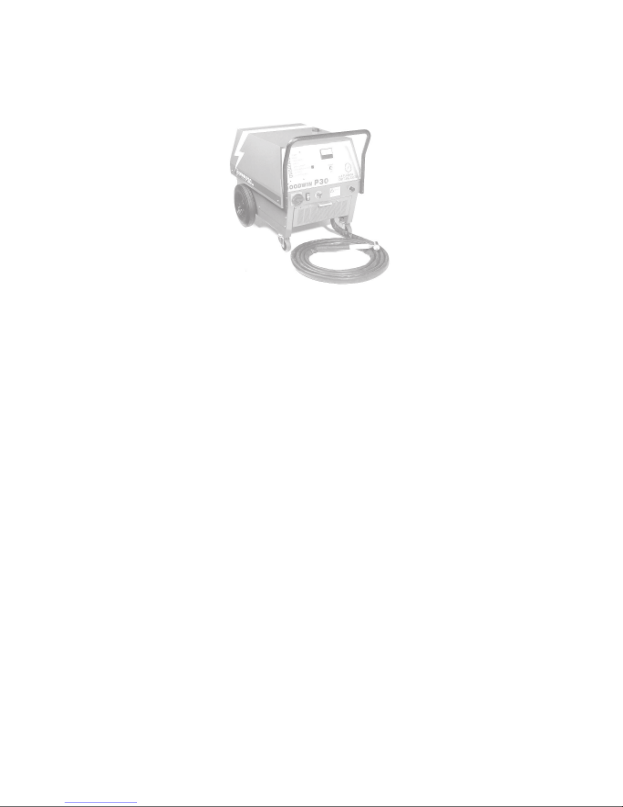
GOODWIN P30
AIR PLASMA CUTTING SYSTEM
P30 Instruction Manual Revision : 5 9th May 2008
Page 2

Page : 2 P32 Manual.p65 Issue 3 9th May 2008
The Company reserves the right to make such changes to the design or specification of the
equipment as it shall see fit. The information contained in this manual is issued for the guidance
of users and does not form part of any contract. It is strongly recommended that all users and
supervisors familiarise themselves with the contents...
PRIOR TO COMMENCING USE OF THE SYSTEM
...and in particular, the section on safety precautions which should be used as a guide to
safe operation in accordance with the requirements of the relevant Health and Safety at Work
legislation.
GOODWIN AIR PLASMA LIMITED
KERNAN DRIVE
LOUGHBOROUGH
LEICESTERSHIRE
LE11 5JF
ENGLAND
Tel No. ++(0) 01509 237369
Fax No. ++(0) 01509 234942
Email. goodwinplasma@aol.com
Page 3

P32 Manual.p65 Issue 3 9th May 2008 Page : 3
Contents
1. ................................................................................................................................................. SAFETY 4
1.1 ................................................................................................................................................. General 4
1.2 .....................................................................................................................................Safety Features 5
1.3 ...................................................................................................................................... Warning Signs 5
1.4 ...................................................................................................Packaging Handling and Transport 5
2. ............................................................................INTRODUCTION TO THE PLASMA PROCESS 6
3. ................................................................................................................................... INSTALLATION 7
3.1 ....................................................................................................................................... Power Supply 7
3.2 ............................................................................................................................ Earth Requirements 7
3.3 ........................................................................................................................... Phase Determination 8
4. ........................................................................................ PLASMA AND TORCH CONNECTIONS 9
4.1 ................................................. Connecting the Torch and Plasma Earth Lead to the Power Unit 9
4.2 ...................................................................................................................... Control of Hand Torch 10
5 ........................................................................................................................................ OPERATION 11
5.1 ...............................................................................................................................Machine Controls 11
5.1.1 ..........................................................................................................................warning indicators 13
5.2 ......................................................................................................................... Power Up Procedure 14
5.3 ............................................................................................................................. Cutting Procedure 15
5.3.1. ....................................................................................................... Starting and Finishing a Cut. 15
5.3.2. ................................................................................................................Cutting With Stand Off. 15
5.3.3. ................................................................................................................................Cutting Speed. 16
5.3.4. ..........................................................................Piercing Thicker Materials with a Hand To rch 17
5.3.5. .................................................................................................... Piercing with a Machine Torch 18
5.4 ................................................................................................................................. Troubleshooting 19
5.5. .............................................................................................................................. Consumable Life. 19
5.5.1. ...................................................................................................................................Intrinsic Life. 19
5.5.2. ...................................................................................................................................... Alignment. 19
5.5.3. .........................................................................................................................Transient Damage. 19
5.5.4. .................................................................................................................... Operational Damage. 20
5.5.5. ................................................................................................................Electrode “non-starting”.20
5.6 .....................................................................................................................Changing Consumables 21
6. ........................................................................................................................... TECHNICAL DATA 23
6.1 ..........................................................................................................................................Power Unit 23
6.1.1. .............................................................................................................................. Electrical Input 23
6.1.2. ........................................................................................................................... Electrical Output 23
6.2 ............................................................................................................................ Torch and Hose Set 23
6.2.1 ......................................................................................................................................Hand Torch 23
7. ............................................................................................................... SERVICE INFORMATION 24
7.1 .................................................................................................................................. The Power Unit 24
7.1.1. ............................................................................................................................. Circuit Diagram 25
7.1.2. ............................................................................................................................. Machine Layout 26
7.1.2. ....................................................................................................................Diagnostic Indicators. 28
7.2 ........................................................................................................The Torch and Hose Set Repair 29
7.3 ....................................................................................................................................... Maintenance 30
8. .....................................................................................................................................Torch Blockage 31
8.1 ................................................................................................................................... Machine Torch 31
8.2 ......................................................................................................... Machine Torch exploded View 32
8.3 .........................................................................................................................................Hand Torch 33
8.4 ...............................................................................................................Hand Torch exploded View 34
9. ........................................................................................................................................Fault Finding 35
10. ................................................................................................................................................... Index 36
A36
Page 4

Page : 4 P32 Manual.p65 Issue 3 9th May 2008
1. SAFETY
1.1 General
Before any cutting operations are started, the user must ensure that the installation and
proposed working methods comply with all relevant safety regulations, environmental and electricity standards.
The plasma arc produced at the torch head is a jet of high energy and is potentially dangerous. Users unfamiliar with a plasma arc should seek basic training. Goodwin Air Plasma can
offer comprehensive training courses.
In addition, the following points are particularly important:
a) The mains connection must be properly grounded and the supply lines fitted with fuses of
the specified rating. The mains cable must be properly secured and protected from possible
damage.
b) High voltage exists at the torch when power is applied and the pilot arc is struck (up to
95V), and when the main arc is cutting (95V). Under no circumstances should anyone
touch the nozzle with power applied to the torch. All adjustments and replacement of parts
should be done with the power unit supply isolated. The torch should not be used in
excessively wet conditions or if the torch or hose set are damaged in any way .
c) The mains supply should be isolated from the unit A T THE SUPPL Y before removing any
panels from the unit. Only authorised service personnel should remove panels.
d) Keep the work area clear of all inflammable materials. Ensure that any material ejected
from the cut is not a hazard to the operator or to others.
e) Protection is necessary against ultraviolet radiation emitted from the arc. A helmet or
shield with shade glass is recommended. W ear gloves and adequate protective clothing
where appropriate. Adequate screening should be arranged to protect others in the vicinity
or passing by in a similar manner to that required for arc welding operations.
f ) Adequate ventilation or fume extraction to remove the cutting fume and dust is required at
all times around any plasma cutting operation. When cutting flat sheet, a shallow water
bed cutting table will greatly reduce the fumes and dust which mainly occur below the cut.
g ) The plasma power unit should be positioned on stable level ground and if necessary
secured against any unwanted movement.
h ) The operation of this equipment and the plasma cutting process can result in noise levels
that could be harmful. The employer should undertake a noise assessment to monitor
compliance with relevant legislation.
i ) Material to be cut should be supported in such a way that any material cut from the work
piece will not be a hazard and fall onto the user, the equipment, or others in the vicinity.
j) Care should be taken when manoevering the hose set with the hand held torch so that it
does not snag on objects or other equipment which may result in damage to the hose set, or
topple the objects or equipment. Excessive mechanical tension may result in damage to the
hose set connections or to the hose set components themselves.
Page 5
P32 Manual.p65 Issue 3 9th May 2008 Page : 5
1.2 Safety Features
The plasma unit includes the following features for the safety of the operator:
* The body of the plasma torch is earthed.
* The continuity of the torch earth and the voltage on the body is monitored.
* Cutting current flowing in the supply earth is monitored.
* The voltage on the torch nozzle is monitored.
* In the event of a faulty condition of the above, the machine will switch off power to the
torch.
* The access door for the torch connections is interlocked.
The emergency stop procedure is to hit the red emergency stop button located on the lower front
control panel.
A tool (10mm spanner) is required to remove the canopy for access to the internal components.
Under no circumstances should the canopy be removed whilst the mains supply is still connected. Only suitably trained and authorised personnel should remove the canopy .
1.4 Packaging Handling and Transport
Should the plasma unit need to be shipped, we recommend re-use of the original packing crate.
Also:-
a) That the hose set be disconnected to prevent any damage to the hose set / plasma connections.
b) That the control panel is adequately protected against potential damage.
c) Any lifting should be done using the eyebolt located in the top of the canopy together with
certified lifting equipment (not supplied). Precautions should be taken to prevent rotation about
the eyebolt.
d) The plasma unit should be shipped and stored in the upright position to avoid any heavy
internal components breaking free from their mountings.
e) Storage should be undercover, preferably in a clean dry environment.
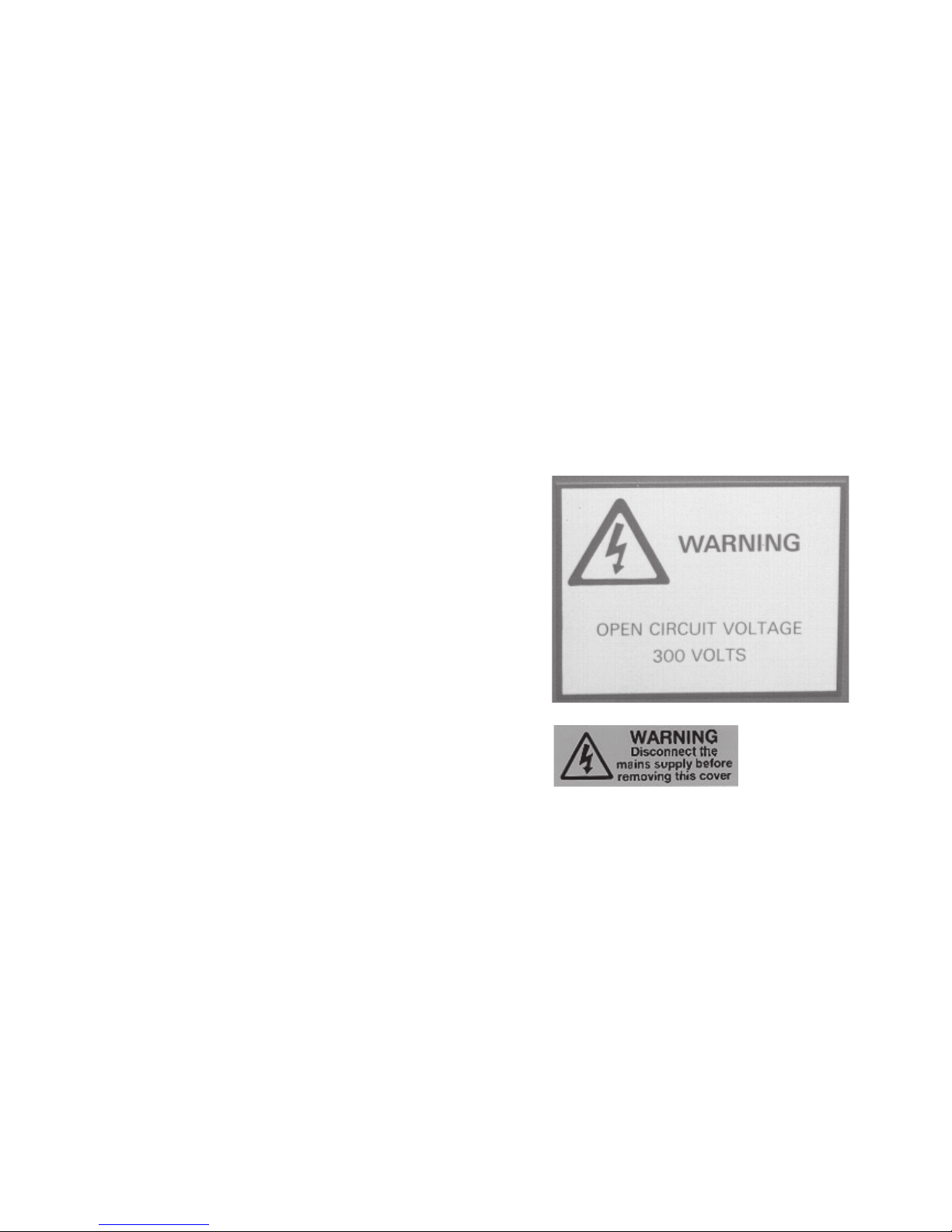
1.3 Warning Signs
The location of the warning signs fitted to the
plasma unit are:
a) At the front of the machine Warning Open Circuit Voltage 300 volts.
b) At each rear lower corner of the canopy -
Warning Disconnect the Mains Supply.....
These should be maintained in a legible condition.
Page 6

Page : 6 P32 Manual.p65 Issue 3 9th May 2008
2. INTRODUCTION TO THE PLASMA PROCESS
The plasma process is created by passing a stream of clean ionised air, provided by an oil free
compressor, through a NOZZLE in the torch. The air stream is ionised by a PILOT ARC,
initiated by a HIGH FREQUENCY unit (HF Unit) which passes from the ELECTRODE to the
nozzle when the torch is activated. When the PILOT ARC is brought close to the work piece,
MAIN ARC is TRANSFERRED to the work piece as a jet of high energy which rapidly melts
any metal with which it makes contact, providing fast cutting, low residual heat input, and low
material distortion.
The electrode and nozzle are cooled by air (and water in water cooled torches), and as the air is
passed through the nozzle it is caused to swirl around the arc by a SWIRL BUSH to aid stability
of the arc.
The HF unit operates automatically to establish an arc when power is applied to the torch and it
ceases to operate when the pilot or main arc is established.
Page 7
P32 Manual.p65 Issue 3 9th May 2008 Page : 7
3. INSTALLATION
May be carried out by a competent electrician. No specialist tools are required.
3.1 Power Supply
The power unit is provided with a length of flexible cable which must be connected to a 3 phase
and earth electrical supply . The supply should be fitted with fuses or circuit breakers of
appropriate rating and a means of isolating the power unit from the supply should be provided. A
plug should be fitted if appropriate. The machine is phase/rotation sensitive.
The power unit has power factor correction capacitors fitted as standard. It must be noted that when
the unit derives its power from a generator, the power factor correction may disturb the generators'
automatic voltage control. If recommended by Goodwin Air Plasma, the power factor correction
circuit can be disconnected however this will increase the input current demand.
Refer to the rating plate on the machine and Technical Data section 6.1.1. for the correct voltage
and current requirements.
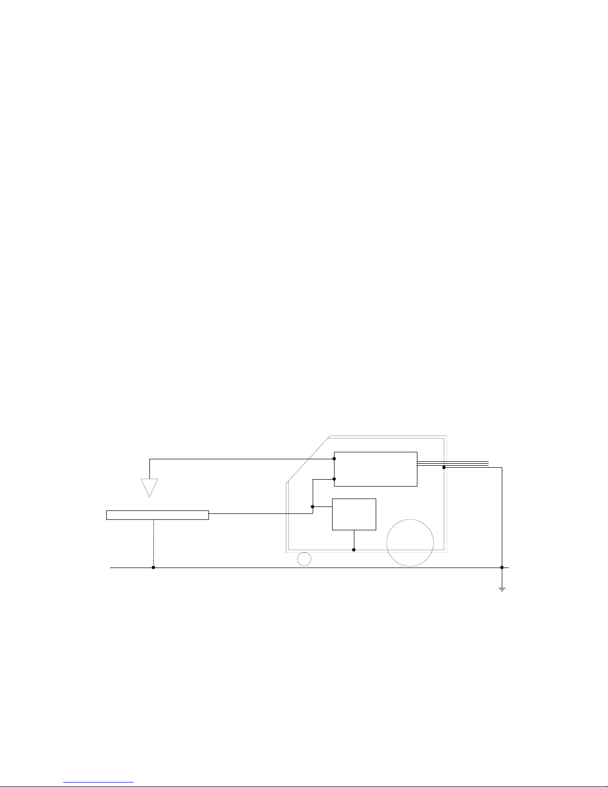
3.2 Earth Requirements
The installation should be arranged such that the only path to earth (or ground) from the work
piece is by way of the plasma earth lead connected to the front of the machine.
Where the material to be cut forms part of the structure which is earthed or grounded to the
mains electrical supply system, then the cutting current could flow through that route rather than
the plasma earth lead to the machine. Always ensure that there is a good connection between the
work piece and the machine via the plasma earth lead as a poor connection will cause excessive
current in the mains supply earth which will create a current trip fault condition (see section 7.4
fault finding).
In installations where it is not possible to avoid earth current trips, even though a good cutting
current earth path has been ensured, it will be necessary to check that the alternative mains earth
paths are substantial enough to carry higher currents than the current trip setting of 10 amps
without causing damage, as where the cutting earth is not connected to the work piece at all, this
would be the full cutting current. If the earth paths are not substantial they must be uprated or rerouted to avoid the possibility of damage. Once the necessary checks and precautions have been
taken, the earth current trip circuit may be disabled by means of the switch on the Earth Current
Relay (ECR) located inside the power unit.
PLASMA
TORCH
PLASMA
MACHINE
WORK
PIECE
MAINS
SUPPLY
PLASMA EARTH LEAD
POSSIBLE ALTERNATIVE PATH
+
-
PLASMA
POWER SUPPLY
FOR CUTTING CURRENT
EARTH
CURRENT
RELAY
Page 8
Page : 8 P32 Manual.p65 Issue 3 9th May 2008
3.3 Phase Determination
Connect the torch to the machine (see section 4).
Fill the water system with distilled water.
Note. T o avoid damaging the water pump the machine should not be run without water in the
system, also, the machine should not be run for more than a few seconds without a torch connected to
the machine.
Switch on the machine by rotating the main isolator and pressing the on/off button ensuring the
emergency stop switch is unlatched.
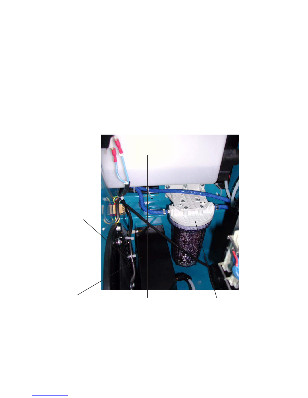
Correct phase connection is determined by checking that the cooling air flowing through the power unit
is from the front panel to the rear of machine. Also, the water return flow , with a torch connected, can
be seen as a jet of water inside the water tank through the filler opening once the filler cap is removed. If
the fan rotation not correct, change two of the three phase connections at the power supply and check
again.
If there is any doubt regarding installation, consult your distributor or Goodwin Air
Plasma.
Fan Rotation AntiClockwise
W ater Jet inside
W ater T ank
Compressed Air
Cooling Radiator
Optional W ater
Filter
Page 9
P32 Manual.p65 Issue 3 9th May 2008 Page : 9
4. PLASMA AND TORCH CONNECTIONS
4.1 Connecting the Torch and Plasma Earth Lead to the
Power Unit
EURO PLUG TORCH
CONNECTOR
W A TER RETURN
W A TER SUPPL Y
DIAGRAM TO SHOW HOSE SET CONNECTIONS
Note. Do not run the power unit without the torch connected.
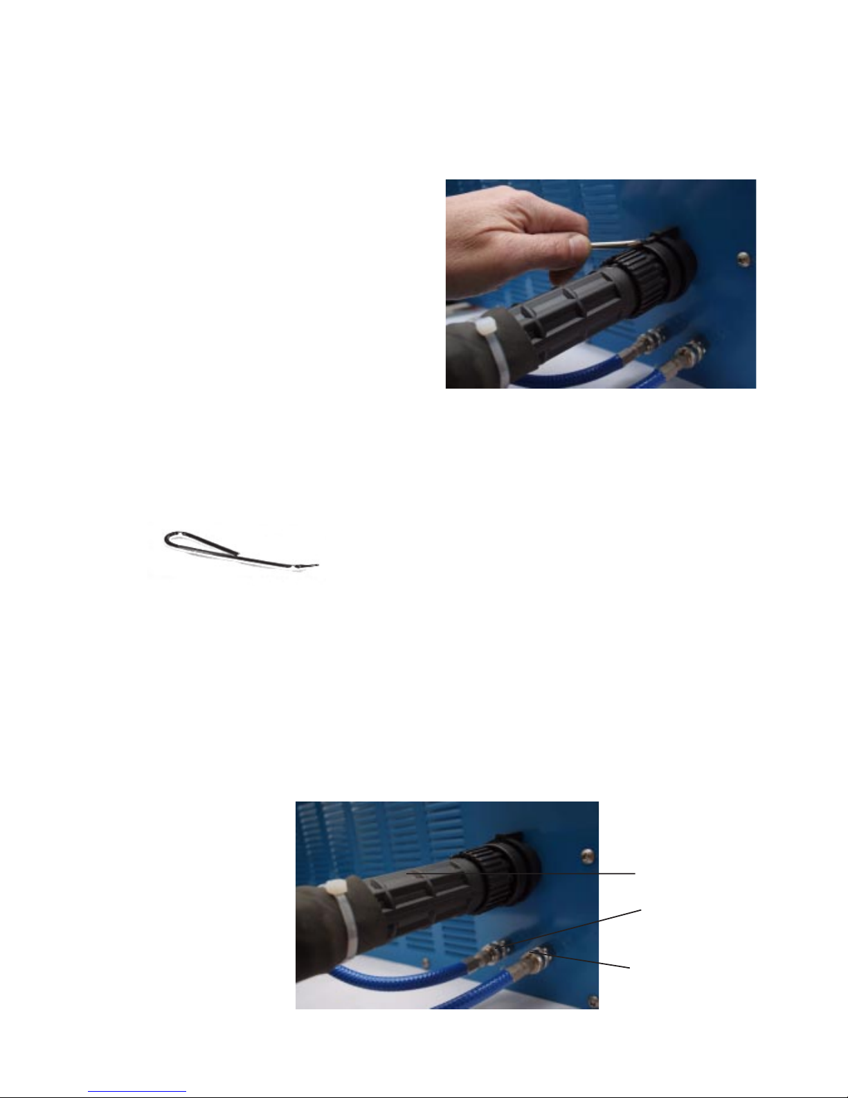
POINTED TOOL
The plasma earth lead is connected via the push in and twist clockwise socket.
The water fittings cannot be fitted incorrectly although the return line (long) will fit in the supply outlet
(short) for back flushing the torch. T o remove the water hoses, push the water connector collars to
release (both together to avoid loss of water).
When first switching on, allow enough time for the water to circulate through the system. A solid flow
of water should be seen inside the filler orifice when the filler cap is removed, top up the header tank as
required. Use only distilled or de-ionised water. (See section 7.1 regarding use of methanol in freezing
conditions).
T orch connection to the power unit is made by a
"push in" connector plug to a socket on the front
of the power unit designed to prevent accidental
removal of the hose set. A pointed tool is supplied
in the tool kit for the purpose of allowing the hose
set to be connected and disconnected.
T o connect the hose set, insert the connector plug
into the socket and press the pointed tool into the
small hole (see illustration), whilst rotating the
knurled securing collar.
Note that a sealing ring is located in the base of the torch connector socket to form an air seal with the
centre power pin. Care should be taken to ensure that this seal is not displaced and that the end of the
pin is not damaged when the torch plug is removed.
Page 10

Page : 10 P32 Manual.p65 Issue 3 9th May 2008
4.2 Control of Hand Torch
The hand torch is provided with a press on / release off control switch on the handle for operation
of the plasma arc.
Note. Cooling air will flow through the torch at all times when the machine is switched on.
If a hand torch is to be used in conjunction with a mechanical manipulator or tractor unit etc.,
when the operation of the handle mounted press on / release off control switch will not be
possible, plug the remote control (optional extra) switch unit into the remote control socket as for
the machine torch.
Page 11

P32 Manual.p65 Issue 3 9th May 2008 Page : 11
WARNING
INDICATORS
ON / OFF
BUTTONS
MAIN ISOLATOR
EMERGENCY STOP
OUTPUT ON LAMP
AIR PRESSURE
GAUGE
AIR REGULA TOR
RESET BUTTON VOLTMETER
5 OPERATION
5.1 Machine Controls
The front panel of the machine provides a range of displays and control gear to ensure correct
operation
ON / OFF BUTTONS
Switches auxiliary circuits on and off. ie Compressor, water pump, cooling fan and control circuits
MAIN ISOLA TOR
Isolates machine from mains supply. It may be padlocked in the off position.
EMERGENCY STOP
Switches machine off. The switch latches mechanically and must be rotated to release.
Page 12

Page : 12 P32 Manual.p65 Issue 3 9th May 2008
HOSE CONNECTIONS
See section 4. Connectiong the torch to the power unit.
VOLTMETER
Indicates the arc voltage.
Typical values would be: Power applied to torch but no arc 300v
For Pilot Arc 250 to 280 volts
For Main Arc 120 to 180 volts
OUTPUT ON LAMP
Indicates that power is applied to the torch.
RESET BUTTON
Resets earth current, earth safety , low arc voltage and water warning circuits.
AIR PRESSURE GAUGE
Displays the back pressure in the system during the pilot arc and cutting modes
Typical values would be: For Pilot Arc 0.7 to 1.4 bar (10 to 20 psi)
For Main Arc 2.4 to 3.4 bar (35 to 50 psi)
AIR REGULATOR
Sets the air flow through the torch to give a stable pilot arc.
Page 13

P32 Manual.p65 Issue 3 9th May 2008 Page : 13
POWER
READY
TEMPERATURE
WATER
EARTH CURRENT
EARTH SAFETY
PILOT TRIP
LOW ARC VOL TAGE
POWER INDICATOR Indicates that power is available to the system control circuit.
READY INDICATOR Indicates system interlocks are operational and the machine is ready to cut
TEMPERATURE INDICATOR Indicates that the rectifier or transformer temperature is too high.
WATER INDICA T OR Indicates insufficient water flow in the torch.
EARTH CURRENT INDICATOR Indicates excessive currents in the supply earth (see section 3.2).
EARTH SAFETY INDICATOR Indicates a break in the earth connection to the torch or a voltage in excess of 10 volts to the torch
body .
PILOT TRIP INDICATOR Indicates the pilot arc has excessive current, due to consumable condition or insufficient air flow.
5.1.1 WARNING INDICATORS
See section 7.1.2 Displays and Controls for more details.
Page 14

Page : 14 P32 Manual.p65 Issue 3 9th May 2008
5.2 Power Up Procedure
Having completed the mains and cutting earth wiring, connected the torch and checked the fan
rotation, the machine is ready for use.
Switch the machine on and after allowing time for the water to circulate through the torch, press
the reset button on the front panel. The red indicators should go out and the ready light will
illuminate.
To ascertain the absence of air leaks, the air regulator should be wound fully clockwise and the
pressure gauge should indicate a back pressure in excess of 1.6 bar .
It is now necessary to adjust the air pressure to give the highest possible reading consistent with
good arc starting and a stable pilot arc, this should around 0.9 bar . Switch on the torch with the
nozzle well clear of any work piece, person or equipment, and re-adjust the air pressure until it is
at maximum or the pilot arc becomes unstable (very noisy, misfire, and the voltmeter showing
300 volts). At this point reduce the pressure to restore stability (arc less noisy, stable arc, and the
volt meter showing 250/280 volts).
Always maintain as high an air pressure as possible for pilot arc as this gives the best consumable life.
The output neon is “on” and the voltmeter reads between 250 vdc and 280 vdc at this stage.
The machine is now setup and is now ready to be used. Before starting a cut please see section 1
for safety information and then section 5.3 for cutting procedure.
NOTE.
As plasma power units do not have a voltage stablised power supply, a fluctuation in the input
voltage will directly affect the output current. This may not be noticeable if the input voltage
rises slightly above the norm as it will provide more power for cutting. If the rise is excessive,
consumable life may suffer. However, when the input voltage falls, the output power also falls,
affecting both the pilot arc and main arc. In these circumstances it will be necessary to adjust the
air pressure regulator to reduce the airflow to obtain a stable pilot arc, and readjust it when the
mains voltage returns to normal.
Page 15

P32 Manual.p65 Issue 3 9th May 2008 Page : 15
IMPORTANT
If the arc should “flare”, be coloured green, or emit any unusual noise, it is recommended that the
unit be immediately switched off and the condition of the consumables checked. Cutting under
these conditions may result in damage extending beyond the consumables to other parts of the
torch.
Under normal cutting conditions the torch is designed
to operate with a STAND OFF of about 6 mm (except
P50 8 mm). This is the distance between the end of the
nozzle and the work piece.
Where the work piece is rusty, scaly, or with thick
sections of steel or aluminium etc., a build up of dross
on the top of the work piece may occur which will
cause damage to the nozzle. In these conditions, the
stand off distance should be increased slightly.
A guide ring is avalable to assist the operator in
maintaining the desired stand off height. This can also
be used against a straight edge to maintain a straight
cut.
5.3.2.Cutting With Stand Off.
5.3 Cutting
Procedure
Where possible it is better to start a cut at a plate edge or hole because the piercing process
reduces consumable life.
Cuts can be started by either initiating the pilot arc and moving the torch into the proximity of the
work piece, or by positioning the torch over the edge of the work piece and starting the pilot arc.
Materials with a capacity to absorb heat energy, especially thicker sections, require more care and
technique when starting a cut. In these cases the cut will appear slow to start and pierce through
the material. Once a cut is established then cutting speeds may be increased.
Cutting can be stopped either by releasing the torch switch, switching off the power , or by withdrawing
from the workpiece (best done rapidly).
5.3.1.Starting and Finishing a Cut.
Page 16

Page : 16 P32 Manual.p65 Issue 3 9th May 2008
5.3.3.Cutting Speed.
Best results are usually obtained by cutting at the optimum cutting speed.
OPTIMUM CUTTING SPEED
Correct cutting speed is judged by experience from
observing the angle at which the cut material leaves
the lower edge of the plate, either by observing the
ejected material or by studying the surface of a cut
after completing a test cut. The drag back of the arc is
aproximately 30 degrees.
CUTTING TOO SLOW
Arc appears to blow straight through the material.
Excessive dross may accumulate on the underside of
the material.
CUTTING TOO FAST
Arc fails to pierce the material. Blow back of dross
will damage the nozzle.
MAXIMUM CUTTING SPEED
Drag back of the arc is around 45°, but cut quality will
deteriorate.
Page 17

P32 Manual.p65 Issue 3 9th May 2008 Page : 17
5.3.4.Piercing Thicker Materials with a Hand T orch
Piercing will cause cut material to be ejected upwards which can be dangerous, and has a risk of
damaging the torch nozzle. This problem is worsened as material thickness increases because it
takes longer to pierce. If it is necessary to pierce, then it is best done by angling the torch and
gradually bringing it upright as piercing is completed.
Initiate the pilot arc and lay the torch over at approximately
60º
Begin twisting the torch slowly towards a vertical position
taking care to avoid ejected material from hitting the
nozzle. At the same time, the torch should be moved a
small distance along the work piece.
As piercing completes, the nozzle can be brought to vertical
and cutting can continue.
If the torch is pivoted about the nozzle there is a risk of material
being blown back onto the nozzle which will cause damage to
the nozzle or even to the torch itself.
*
Imaginary pivot point. X
X
X
X
X
Page 18

Page : 18 P32 Manual.p65 Issue 3 9th May 2008
5.3.5.Piercing with a Machine T orch
When using a machine torch, it is not generally possible to angle the torch for piercing.
Start the pilot arc above the work piece, and with the torch travelling at about half of the normal
cutting speed, lower the torch until main arc transfer occurs.
Once piercing is complete, the torch may be brought to normal stand off and cutting speed.
Goodwin Air Plasma offer an Automatic Height Control Unit as an optional extra for machine
torches integrated with profiling machines or robot arms. Ask your distributor or Goodwin Air
Plasma for further details.
STAND
OFF
20MM
15MM
10MM
NORMAL
ê
è
Position the torch around 20mm from the work
piece, start the pilot arc and torch manipulator
moving at half speed.
Lower the torch until main arc transfers.
At this point, the descent speed of the torch is
important. If it is too fast, the ejected molten
metal will damage the torch.
Continue to lower the torch slowly after arc
transfer until the nozzle is 10mm from the work
piece.
Wait until the arc has completed piercing
through, then lower the torch and maintain a
normal stand off for the duration of the cut.
Cutting can now continue at the full
recomended speed.
è
è
è
ê
ê
è
Page 19

P32 Manual.p65 Issue 3 9th May 2008 Page : 19
Bevel is more noticeable on thinner sections and is more pronounced on the left hand side of a
cut. It is due to the clockwise swirling of the air induced by the swirl bush in the electrode assembly. Bevel edges can be desirable as an aid to weld preparation, however it can be virtually eliminated by reducing the cutting speed but at the expense of accumulated dross. For minimum bevel
cut clockwise around a component and anticlockwise in a hole.
5.5.Consumable Life.
A good consumable life is the single most important factor in achieving optimum cutting
economics of any plasma cutting unit. This life is dependent on the intrinsic life of the
consumables, correct alignment and the incidence of transient and operational damage.
5.5.1.Intrinsic Life.
The intrinsic life of the consumables is determined by the rate at which they are eroded by the arc
process. This erosion rate is however low, and in practice, the life is limited by other factors. The
insert in the centre will be eroded slightly each time the arc is struck eventually creating a visible
crater. The crater can be more than 2mm deep before the electrode is considered to be expired.
5.5.2.Alignment.
The alignment and construction of the Goodwin Air Plasma Torch is such that problems of
grinding and adjusting electrodes do not occur . With reasonable care taken in fitting the
consumables, alignment problems should not arise.
5.5.3.Transient Damage.
On starting directly onto main arc, it is occasionally possible to erode some of the copper from
the electrode before the arc settles onto the insert material. This generates a crater in the
electrode and the insert burns back to become flush. Consumable life is thus reduced if there is a
high number of starts relative to the total cutting time.
Cutting speed too slow. Torch consumables worn or damaged.
Insufficient air flow .
Damaged torch consumables. Nozzle blocked by dross or too close
to work piece. Insufficient air flow.
Nozzle orifice damaged. Electrode eroded “off centre”. Consumables
wrongly fitted.
Speed too high. Stand off too high. Arc not straight - consumables
damaged or misaligned.
Excessive dross on lower
edge of cut.
Double arcing.
Main arc not square to
work piece.
Excessive bevel or
rounded cut surface.
5.4
Troubleshooting
Page 20

Page : 20 P32 Manual.p65 Issue 3 9th May 2008
5.5.4.Operational Damage.
This is the most likely cause of limited consumable life. Since the arc is quite capable of cutting
copper, anything which causes the arc to deviate from the centre of the nozzle will result in
damage to the orifice. In extreme cases the arc passes not through the orifice but from the
electrode to the nozzle and from the nozzle to the work piece - DOUBLE ARCING, causing the
rapid erosion of copper from both electrode and nozzle.
The most common cause of these problems is from ejected cut material entering the orifice
particularly when piercing or obstructing the nozzle with the work piece.
It is best to operate within the maximum speed capabilities of the machine and avoid unnecessary
piercing or stop-start cutting whenever possible.
5.5.5.Electrode “non-starting”.
Occasionally, it may happen that it is difficult to start the pilot arc. This happens when the
oxidized material from the electrode insert is deposited over the surface of the copper electrode
and inside the nozzle. Starting can be improved by cleaning or scratching the surface of the
electrode with a wire brush or sharp implement. Always switch off the power unit before
removing the nozzle for this purpose. Once a “non-starting” electrode has been used a few times,
starting usually improves.
It is not good practice to fire the pilot arc continually in midair without striking the cutting arc as
this oxidizes the surface of the electrode and leads to “non-starting” problems.
Since cutting usually improves a non-starting electrode, it may be desirable to use a piece of
scrap material and start the main arc immediatly by positioning the torch close to the material
before switching on. Once started, continue to cut for as long as possible before trying to reinitiate the pilot arc.
ILLUSTRATION TO SHOW ELECTRODE DAMAGE
NEW ELECTRODE
USED ELECTRODE
WORN OUT
EXPIRED
Page 21

P32 Manual.p65 Issue 3 9th May 2008 Page : 21
5.6 Changing Consumables
The Goodwin Water Cooled torch carries a number of elements known as the CONSUMABLES
which are eroded during the cutting process. They consist of:
a) Nozzle.
b) Electrode Assembly comprising:
Electrode
Swirl Bush
O ring
Other parts that may be damaged and replaced by the user are:
Front Cap
Front Cap Retaining Ring
Contact Tube.
TORCH HEAD
FRONT CAP RETAINING RING
CONTACT TUBE
ELECTRODE ASSEMBLY
NOZZLE
FRONT CAP
Page 22

Page : 22 P32 Manual.p65 Issue 3 9th May 2008
To renew the consumables, the following procedure should be adopted, remembering that care
and cleanliness are of the utmost importance.
1. Switch the machine off at the mains supply or Main Isolator .
2. Remove the Front Cap. The cap is a push fit over the O ring seated in a groove in the outer
diameter of the T orch Body.
3. Unscrew the Nozzle with the special
tool supplied. (See illustration left).
4. Check the condition of the Electrode
Assembly. If it is to be removed, grip the
Electrode Assembly with the special
Electrode Pliers provided, and pull firmly
out from the torch body . (See illustration
right).
5. Press a new Electrode Assembly carefully but firmly over the contact tube until it is fully
home and central. Use the handle of the Nozzle Tool which has been prepared for this purpose.
THIS IS VER Y IMPORTANT ! If the Electrode is not pressed fully home onto the Contact
Tube, the Swirl Bush may be partly crushed by the Nozzle, and will interfere with the airflow.
6. Carefully screw the Nozzle into the Torch Head using the special tool until fully home. DO
NOT OVER TIGHTEN.
7. Apply a liberal quantity of Silicone Grease around the front of the torch.
8. Refit the push fit Front Cap. Apply additional grease over the outside of the front cap. The
grease will provide a first line of defence against material blown back from the cutting
process.
Remember that cleanliness and care must be taken when fitting consumables. Do not allow dirt
to obstruct the threaded parts of the torch. Take care when engaging threaded parts not to damage
the thread.
CONTACT TUBE REPLACEMENT .
Should the Contact Tube need changing, it is removed by inserting the 1/8" allen key supplied
into the centre and unscrewing. Replacement is the reverse of removal but it is important not to
over tighten as this may cause subsequent electrode fitment to be off centre, producing bevel
cuts.
Page 23

P32 Manual.p65 Issue 3 9th May 2008 Page : 23
6. TECHNICAL DATA
6.1 Power Unit
6.1.1.Electrical Input
Input is via 3 core and earth flexible: 4 x 16mm2 3 metre length standard.
Machines are available for the following 3 phase supplies:
Note. When the power unit is connected to a generator it may be necessary to disconnect the power
factor correction capacitors in the power unit if they disturb the generator's automatic voltage control.
This does however increase the demand at full power .
With PF Without PF
Input Voltage Correction Correction
380v 50Hz 58 amp 90 amp
415v 50Hz 53 amp 85 amp
460v 60Hz 48 amp 83 amp
Other voltages and frequencies available to order
6.1.2. Electrical Output
Open circuit voltage 300v dc
T ypical arc voltage 150v dc
Main arc power 30kW
Pilot arc current 15 - 20 amps nominal
Duty cycle 100%
6.1.3 Miscellaneous
Compressor type Oil free twin cylinder.
Water pump type Regenerative type.
W ater capacity 5 litre (aprox. dependant on hose length)
distilled or deionised water
6.1.4. Dimensions
Length 800mm (26") inc wheels and handle.
Width 700mm (22") "
Height 1200mm (48") "
Weight 302 kg ( 666 lb)
6.2 Torch and Hose Set
6.2.1 Hand T orch
T orch body diameter 40mm
T orch head weight 1.0 kg
Effective weight (inc. hose set) 1.5 kg
Hose set lengths available 7.5m, 15m, 20m, 30m, longer with Junction Box.
Hose set water capacity 0.6 litres per 10m length
Page 24

Page : 24 P32 Manual.p65 Issue 3 9th May 2008
7.1.1. Main Circuits and Systems.
7. SERVICE INFORMATION
7.1 The Power Unit
Output power is supplied from a fan cooled transformer and rectifier with varistor diode protection.
The transformer is rated at 100% duty cycle and is protected by a thermostat.
The power is carried to the torch electrode by a cable within the hose set.
Pilot arc connection to the nozzle is made via a current limiting resistor in the rear of the
machine and a coaxial cable in the hose set. The HF arc ignition is fully automatic in operation,
being powered from the torch power lines.
The compressor, and cooling fan are the only “phase sensitive” components and it is essential to ensure
that their direction of rotation is correct according to the installation instructions (see section 3).
These components are protected by thermal / magnetic overload switches. If an overload should operate,
after establishing the reason for the trip (e.g. missing supply phase). It can be reset by first removing the
machine cover then pressing the manual reset button on the overload unit situated behind the instrument
panel.
The transformer, water radiator and the pilot arc resistor , are cooled by an electric fan. A temperature
sensing interlock inside the transformer windings protects the system against thermal overload
should the cooling fail or be obstructed hence it is essential to ensure adequate air circulation
around the machine at all times.
The air compressor is of the oil free, maintenance free, twin piston type fitted with two cleanable/
replaceable inlet filters contained in black screw-in housings with a snap open lids.
The high pressure water pump supplies cooling water to the torch through quick release, self sealing
couplings so that the torch can be disconnected without the loss of water from the system. There is
an interlocked flow sensor on the return line which shuts down the arc if the water flow should be
restricted.
The header tank must be kept full of distilled water at all times. If site conditions dictate that
antifreeze should be used, then up to 33% METHANOL may be added.
NOTE. Ethylene glycol or automotive type antifreeze fluids MUST NOT BE USED, as they will
cause rapid corrosion of the torch.
Whenever any of the interlocks come into operation the appropriate warning light on the front
panel will indicate to assist in the diagnosis of the problem.
The Circuit Diagram is shown in drawing 1/D/10749
Page 25

P32 Manual.p65 Issue 3 9th May 2008 Page : 25
7.1.1.Circuit Diagram
EDGE OF CABINET
A24
A13
A3
A4
E5
A19
A20
B10B2B1
B3
A7
A8
A11
A12
B6
B7
B5
B11
A1 A2 A9 A10 A5 A6
A22 A23
DOOR
W ATER
E C R
SWITCH
PRESSURE
SWITCH
EAR TH SAFETY
RESET BUTTON
REMOTE
CONTROL
1
2
3
4
SOLENOIDVALVE
OUTPUT
LIGHT
220 VAC 160 VA
18 VAC 10 VA
15 VAC 10 VA
CONTROL
TRANSFORMER
WORK
PIECE
E C R
COIL
R
4.5 ê
1.6 Kw
100K ê
H F
TORCH
BUTTON
3
1
2
TORCH
MAIN
TRANSFORMER
C1
C2
C3
MAIN
CONTACTOR
MOTOR
STAR T 3
1 ~1.63A
MOTOR
STAR T 2
1 ~ 1.63A
MOTOR
START 1
AUX
CONTACT
MAIN
ISOLATOR
L1
L2L3E
AIR COOLING W ATER
COMPRESSOR
FAN
PUMP
MACHINEONMACHINE
OFF
EMEGENCY
STOP
P 30 CONTROL BOARD
1
3
D1
D2
D3
D4
D5
D6
SNUBBER
NETWORK
V
+
E2
5
3
6
4
ACR
B4
B9
FAN ON
HEATSINK
A17
TEMPERATURE SWITCHES ON
POWER TRANSFORMER AND
HEATSINK
EARTH TO
MACHINE
A21
A18
12 VOLT OUTPUT
ACR COIL
A14
A16
1
2
3
A
B
C
D
E
F
TORCH
SOCKET
HAND
TORCH
SOLENOID
VALVE 2
ACR
1 2
E1 E4
(SEE NOTE)
DIX
RS 472-411
P30 S M/C ONLY
SEE 1/D/10751
1/D/10783
1/D/10743
C1
C2 C3
CONNECTED CONNECTED
STAR DELTA
440-575V 60 Hz
TITLE
DR G No.
MATERIAL
SPEC
DRAW N BY
DATE
IF IN DOUBT A SK
NOT TO SCALE
THIS DRAWING IS THE PROPERTY OF GOODWIN AIR PLASMA LTD,
IT IS STRICTLY CONFIDENTIAL, AND MUST NOT BE COPIED,
LOANED, OR DISCLOSED TO OTHER PARTIES WITHOUT THEIR PERMISSION.
COPYRIGHT IS STRICTLY RESERVED.
GOODWIN AIR PLASMA Ltd.
KERNAN DRIVE, LOUGHBOROUGH, LEIC ESTERSHIRE LE11 0JF Tel.01509 237369 Fax.01509 234942
ALL DIMENSIONS IN MILLIMETRES
PETER WILCOCK
ISSUE DATE
CHANGE
CHECKED
BY
REQUESTED
BY
CONFIGURATION DEPENDANT ON INPUT
6/11/97
17/5/94
P30 AND P30S
CIRCUIT DIAG RAM F OR
1/D/10749
MR 150
5
APPLICATION COMPRESSOR STAR TER
P30 EGH3052 466 1.6 TO 2.4 AMP
P30 S EGH610 804 2.4 TO 4.0 AMP
POWER FACTOR CORRECTION CAPACITOR CONFIG ADDED
POWER FACTOR CORRECTION CAPACITORS
Page 26

Page : 26 P32 Manual.p65 Issue 3 9th May 2008
7.1.2. Machine Layout
18
19 16
20
9
4
6
7
5
10
3
11
29 15
12
14
13
8
2728
17
Page 27

P32 Manual.p65 Issue 3 9th May 2008 Page : 27
PARTS LIST
1 ................................................... Volt Meter
2 ............................................... Main Isolator
3 ........................... Motor Starter Compressor
4 ........................................ Motor Starter Fan
5 .......................... Motor Starter Water Pump
6 ...................................... Control Transformer
7....................................... Compressor Filters
8 ........................................................ Diodes
9 ...................................................... H F Box
10 .......................................... Aux Contactor
11.......................................... Main Contactor
12 ....................................... Control P C Board
13 ..................................... Arc Current Relay
14 ................................... Earth Current Relay
15 ...................................................... Fan
16 ...................................... Main Transformer
17 .......................................... Water Tank / Cap
18 ................................Water Pressure Switch
19 .................................... Radiator Assembly
20 ..................................... Pilot Arc Resistor
21 ..................................... Air Pressure gauge
22 ................................................Output Neon
23 ..................................... Air Pressure Regulator
24......................................... Stop/Start Switch
25................................ Emergancy Stop Switch
26............................................... Reset Switch
27................................................Water Pump
28 ................................................ Compressor
29 ........................................... Solonoid Valve
(Not Shown)................................ Dix Connector
(Not Shown). Power Factor Correction Capacitor
(NS) ..(Water fitting, Return) Mini Check Unit Long
(NS) .....(Water fitting, Feed) Mini Check Unit Short
PART NUMBERS
24
23
2
26
25
1
22
21
PX52MV300S
PX50IS99F
PX50CM025
PX50CM010
PX50CM016
PX56A200
PX57CXT01
PX54S0029
PX68MFI0870
PX50CA09
PX50CA80
PX55C10782A
PX68MF10323
PX68MF10565
PX57FA300
PX56M30+VOLTAGE
PX63T10833/PX63M004
PX50SA01
TO ORDER
PX54R0067
PX28100G
PX52BN240A12
PX29R08
PX50SP00Z
PX50SP001
PX50SP01
PX57W500
PX57C400
PX29VS99
PX4201RD300S
PX54C0038
PX29V01
PX29V10829
Page 28

Page : 28 P32 Manual.p65 Issue 3 9th May 2008
OUTPUT ON LAMP
Indicates that power is applied to the torch.
POWER INDICATOR
Indicates that 12V power is available to the system control circuit.
READY INDICATOR
Indicates that all system interlocks including the access door are operational and that the machine
is ready to operate.
TEMPERATURE INDICA T OR
Indicates that the rectifier heatsink and / or main transformer temperature is too high. Cutting
operations will immediately stop. Leave the machine running to allow the fan to cool the
transformer . Systems will automatically reset when the temperature drops.
WATER INDICA TOR
Indicates no water in the system, a water leak, torch blockage, low pump supply pressure or
incorrect motor/fan rotation. See section 7.2 for torch blockage. When water flow is restored, the
system will reset automatically .
EAR TH CURRENT INDICATOR
Indicates the main arc cutting current is flowing in a secondary path. System will stop until the
torch switch is released. (See section 3.2 for cutting earth requirements).
EAR TH SAFETY INDICATOR
Indicates a break in the earth connection to the torch or a voltage in excess of 10 volts to the
torch body . This indicator will also illuminate as a self test when the machine is switched, on
Depressing the RESET button will reset the system provided the fault is rectified.
PILOT TRIP INDICA T OR
Indicates the pilot arc has excessive current. The circuit will reset automatically when the torch
switch is released. Check air flow adjustment, air leaks,restricted air flow , or consumable condition.
7.1.2.Diagnostic Indicators.
Page 29

P32 Manual.p65 Issue 3 9th May 2008 Page : 29
7.2 The Torch and Hose Set Repair
The torch is a precise assembly of electrically conductive parts and P.T.F.E. insulators housed in
a stainless steel body . It is supplied with compressed air, water and electrical power at high
voltage which must not be allowed to escape from their designed confines.
Rebuilding torches requires special training and instruction and is not within the scope of this
manual. Users who wish to repair damaged torches themselves should consult their supplier or
Goodwin Air Plasma for detailed advice.
A torches should be removed from the power unit complete with hose set. Once removed, the
torch head may be serviced or repaired.
If a spare torch and hose set is available, the machine may be put back in service whilst repairs
are carried out.
TORCH BLOCKAGE.
The water flow in the torch can occasionally become blocked, usually with scale because
deionised / distilled water has not been used or has become contaminated. Also, copper deposits
can accure as a result of expiry of an electrode. See section 8 of this manual.
TORCH / HOSE JUNCTION BOX ON MACHINE INSTALLA TIONS .
A Junction box is offered as an optional extra to provide a facility for the fast removal of the
torch head. Useful for service or change of use with minimum loss of production time, the
junction box links all the control services carried by the hose set to the torch. Another advantage
of the junction box is that it will allow the majority of the hose set, which may be lengthy and
difficult to remove from an automatic machine, to remain in situ.
Page 30

Page : 30 P32 Manual.p65 Issue 3 9th May 2008
7.3 Maintenance
Daily
Monthly
(depending on usage)
Annually
more frequently in poor conditions or
with high usage
Check condition of the consumables.
Top up water reservoir with distilled /
demineralised water .
Check for water and air leaks, clean the air
compressor intake filters.
Remove excessive dust from inside the machine
taking care not to damage any mechanical or
electrical component and avoid exposure to this
dust which may represent a health hazard. Use
personal protection as necessary .
Replace the compressor air intake filter. Check
tightness of all electrical and mechanical
connections. Check the correct operation of all
controls and indicators.
Goodwin Air Plasma Cutting Systems are designed so that only a minimum amount of maintenance
is required. By following a regular and careful maintenance procedure, the equipment will give a
long productive life.
Page 31

P32 Manual.p65 Issue 3 9th May 2008 Page : 31
8. Torch Blockage
The torch can become blocked if deionised / distilled water is not used, or with copper deposits
when the electrode expires. In both cases the blockage accrues in the Cathode Block, Centre Insulator
and Nozzle Holder. The torch head will need to be partially dismantled to rectify this condition.
This operation must only be carried out by a competant electrical fitter.
8.1 Machine Torch
1. Remove the Nozzle and Electrode.
2. Remove three small grub screws from mounting tube.
3. Take care not to strain pipe connections to the torch.
4. Pull back the mounting tube and bagging to reveal all the connections of the hose set.
5. Remove safety insulator by carefully cutting with a sharp knife, taking care not to cut the
insulation of the wires inside.
6. Unscrew torch body off the stub tube, put stub tube clear of torch head, and remove Front
Insulator.
7. Slide Back Cover up the Air/Power and Water Pipes to reveal HF Strap and HF Screws.
8. Using a small flat bladed screw driver unscrew the two screws. This will allow the Nozzle
Holder to be removed.
9. Carefully ease out the Centre Insulator taking care not to lose the four Water Seals. This
will reveal the Cathode Block.
10. Clean out the two water galleries using a small drill bit by hand, taking care not to push the
blockage any further into the Cathode Block.
11. Clean holes in the Centre Insulator in the same way.
12. The Nozzle Holder is cleaned in the same way, however this may have a blockage within the
circular water gallery , (check this by blowing into one of the holes, if the air flows freely it is
ok to re-use) if it is blocked it will need replacing before rebuilding the torch.
13. Check Water Seals for damage. Replace if necessary and refit into Centre Insulator.
14. Check length of HF screws as they may have stretched. If they are over 35mm they should
be replaced.
15. Refit Centre Insulator to Cathode Block taking care not to dislodge Water Seals.
16. Refit Nozzle Holder to Centre Insulator taking care to align screws with threaded holes and
tighten.
17. Pull back the Back Cover and Stub Tube taking care to align the two anti-rotation pins with
holes in Back Cover and ensure the Black, Green/Yellow (Earth) and Red (HF) wires are
together.
18. Refit Front Insulator over Nozzle Holder, if this is damaged replace it.
19. Refit Torch Body over torch and screw onto Stub Tube taking care not to cross thread.
20. Fit new Safety Insulator by heat shrinking into place or taping the old one into place taking
care to cover all the exposed metal torch parts.
21 Pull back the Mounting Tube and refit the three grub screws.
22. Refit the Nozzle and Electrode to the torch.
23. Remove water return pipe connection from the Machine (Long water fitting) and start
Machine, allow water to run out until the air lock is released (the water jet will stop then
restart). Run machine for a further five seconds, this will allow any debris left in the torch
head to be ejected. Switch off Machine and reconnect hose set.
NOTE:- If the jet of water coming out of the removed return water connection is not
between 300 to 500mm long then the torch may still be blocked and should be stripped
down completely or sent to Goodwin Air Plasma for repair.
Page 32

Page : 32 P32 Manual.p65 Issue 3 9th May 2008
8.2 Machine Torch exploded View
Page 33

P32 Manual.p65 Issue 3 9th May 2008 Page : 33
8.3 Hand Torch
1. Remove the Front Cap, Nozzle and Electrode.
2. Remove Back Cap and Front Ring (using Special tool).
3. Remove Rear Cover by carefully tapping the side of the T orch on a piece of wood, this will
cause it to fall out. This will reveal the HF Strap and HF Screws.
4. Using a small flat bladed screw driver unscrew the two screws. This will allow the Nozzle
Holder to be removed.
5. Carefully ease out the Centre Insulator taking care not to lose the four Water Seals. This
will reveal the Cathode Block.
6. Clean out the two water galleries using a small drill bit by hand, taking care not to push the
blockage any further into the Cathode Block.
7. Clean holes in the Centre Insulator in the same way.
8. The Nozzle Holder is cleaned in the same way , however this may have a blockage within the
circular water gallery , (check this by blowing into one of the holes, if the air flows freely it is
ok to re-use) if it is blocked it will need replacing before rebuilding the torch.
9. Check Water Seals for damage. Replace if necessary and refit into Centre Insulator.
10. Check length of HF screws as they may have stretched. If they are over 35mm they should
be replaced.
11. Refit Centre Insulator to Cathode Block taking care not to dislodge Water Seals.
12. Refit Nozzle Holder to Centre Insulator taking care to align screws with threaded holes and
tighten.
13. Refit Front Insulator over Nozzle Holder, if this is damaged replace it.
14. Refit Front Ring and Back Cap taking care not to cross thread.
15. Fit Nozzle and Electrode to torch.
16. Remove water return pipe connection from the Machine (Long water fitting) and start
Machine, allow water to run out until the air lock is released (the water jet will stop then
restart). Run machine for a further five seconds, this will allow any debris left in the torch
head to be ejected. Switch off Machine and reconnect hose set.
NOTE If the jet of water coming out of the removed return water connection is not between
300 to 500mm long then the torch may still be blocked and should be stripped down completely
or sent to Goodwin Air Plasma for repair.
Page 34

Page : 34 P32 Manual.p65 Issue 3 9th May 2008
8.4 Hand Torch exploded View
Page 35

P32 Manual.p65 Issue 3 9th May 2008 Page : 35
9. Fault Finding
Below is a list of the most common reasons for non operation of a Goodwin Air
Plasma Cutting System.
Symptom Probable cause Remedy
No Pilot arc at torch head a) Machine Ready Light not on Check for red indicator being on
when torch button is (If so refer to Manual)
depressed b) Output Indicator not on Check torch switch and 220v fuse
As above with output c) Non starting electrode (Refer to manual)
indicator on
d) Volt meter not reading 285v Telephone Goodwin Air Plasma
As above with volt meter
reading 285v e) No HF in HF box Telephone Goodwin Air Plasma
b) Blown diode Telephone Goodwin Air Plasma
Tracking :- a) Slag build up on Front Cap Clean slag from around Nozzle
Spark appears at front of
torch and no pilot arc. b) Front Insulator damaged Replace Front Insulator
Front Caps and Nozzles a) Incorrect operation of torch See operating instruction pages
burning up rapidly
b) Not using Silicone Grease Apply Silicone Grease
Excessive bevel, poor cut a) Damaged Consumables Change Consumables
quality
b) Electrode eroded off centre Change Consumables
c) Misaligned Consumables Change Contact Tube and
consumables
d) Low air pressure Clean air filters, check for air
leaks
e) Cut speed too fast See operating instruction pages
f) Stand off too high See operating instruction pages
f) Broken HF cable on hose set T elephone Goodwin Air Plasma
Current trip indicator a) Electrode incorrectly fitted Refit correctly
coming on
b) Low air flow through torch Increase flow, check for air leaks
c) A path to mains earth Ensure workpiece is completely
isolated from mains earth
Pilot trip indicator coming a) See Above
on
b) None of the above Telephone Goodwin Air Plasma
Low arc voltage indicator a) Air leak in torch or machine Find the leak
coming on
Misfiring pilot arc a) Too much air flowing through Decrease flow
torch
Page 36

Page : 36 P32 Manual.p65 Issue 3 9th May 2008
10. Index
A
Accessory
Junction box 29
C
Consumable
Life of 19, 20
Cutting
Bevel 19
Blow back 20
High Frequency (HF) 6
Main arc 6
Pilot arc 6
Process explained 6
Robot 4
Ventilation 4
Water table 4
E
emergency 5
F
Fault Finding
Bevel 19
Dross 19
Troubleshooting 19
G
Goodwin Air Plasma 2
Guide Ring 15
H
Health and Safety 2
P
Plasma
Process 4
S
Safety
General 4
Mains connection 4
Noise 4
Personal protection 4
Service
Hose 29
Torch 29
Torch blockage 29
T
Training 4
 Loading...