

Page 1

PSM-SERIES PROGRAMMABLE POWER SUPPLY
USER MANUAL
⎯ ⎯
i
CONTENTS PAGE
1. PRODUCT INT RO DU CT IO N............................................................1
1-1. DESCRIPTION.....................................................................................1
1-2. FEATURE............................................................................................2
2. TECHNICAL S PE CI FI CA TI ON S......................................................3
3. PRECAUTIONS BE FO R E O PE RAT I O N.........................................6
3-1. UNPACKING THE INSTRUMENT..........................................................6
3-2. CHECKING THE LINE VOLTAGE .........................................................6
3-3. ENVIRONMENT ..................................................................................7
4. PANEL INTRO DU CT IO N...................................................................8
4-1. FRONT PANEL....................................................................................8
4-2. REAR PANEL BRIEF..........................................................................10
4-3. DISPLAY BRIEF.................................................................................11
5. OPERATION I NS TR UCT I ON..........................................................15
5-1. BASIC OPERATION...........................................................................15
5-2. FUNCTION KEY DESCRIPTION..........................................................16
5-3. OPERATION METHOD......................................................................33
5-4. THE MAXIMUM VALUE OF THE OUTPUT SETTING .............................44
5-5. TEST LEAD ......................................................................................45
PSM-SERIES PROGRAMMABLE POWER SUPPLY
USER MANUAL
⎯ ⎯
ii
6. MAINTENANCE................................................................................46
6-1. FUSE REPLACEME NT.......................................................................46
6-2. LINE VOLTAGE CONVERSION..........................................................46
6-3. MEASUREMENT TECHNIQUES..........................................................47
6-4. ADJUSTMENT AND CALIBRATION....................................................50
6-5. CLEANING.......................................................................................56
7. THE SYSTEM DI AG RA M A ND DE SC RI PT IO N.........................57
7-1. BLOCK DIAGRAM............................................................................57
7-2. THE CONFIGURAT ION OF BLOCK SYSTEM.......................................58
Page 2
PSM-SERIES PROGRAMMABLE POWER SUPPLY
USER MANUAL
⎯ ⎯
iii
SAFETY TERMS AND SYMBOLS
These terms may appear in this manual or on the product:
WARNING. Warning statements identify condition or
practices that could result in injury or loss of life.
CAUTION. Caution statements identify conditions or
practices that could result in damage to this product
or other property.
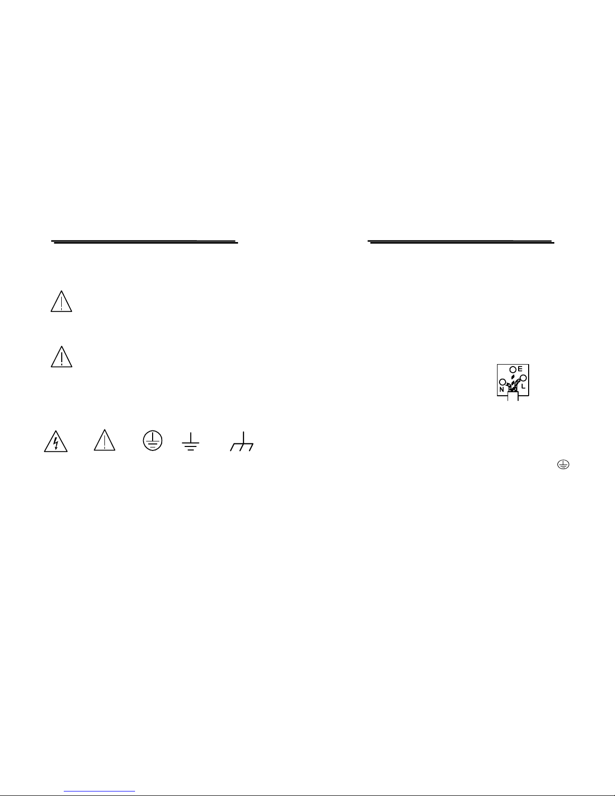
The following symbols may appear in this manual or on the product:
DANGER ATTENTION Protective Earth (ground) Frame or Chassis
High Voltage refer to Manual Conductor Terminal Terminal
Terminal
PSM-SERIES PROGRAMMABLE POWER SUPPLY
USER MANUAL
⎯ ⎯
iv
FOR UNITED KINGDOM ONLY
NOTE: This lead/appliance must only be wired by competent persons
WARNING: THIS APPLIANCE MUST BE EARTHED
IMPORTANT: The wires in this lead are coloured in accordance with
the following code:
Green/ Yellow: Earth
Blue: Neutral
Brown: Live (Phase)
As the colours of the wires in main leads may not correspond with the
colours marking identified in your plug/appliance, proceed as follows:
The wire which is coloured Green & Yellow must be connected to the
Earth terminal marked with the letter E or by the earth symbol
or coloured Green or Green & Yellow.
The wire which is coloured Blue must be connected to the terminal
which is marked with the letter N or coloured Blue or Black.
The wire which is coloured Brown must be connected to the terminal
marked with the letter L or P or coloured Brown or Red.
If in doubt, consult the instructions provided with the equipment or
contact the supplier.
Page 3
PSM-SERIES PROGRAMMABLE POWER SUPPLY
USER MANUAL
⎯ ⎯
v
This cable/appliance should be protected by a suitably rated and
approved HBC mains fuse: refer to the rating information on the
equipment and/or user instructions for details. As a guide, cable of
0.75mm
2
should be protected by a 3A or 5A fuse. Larger conductors
would normally require 13A types, depending on the connection
method used.
Any moulded mains connector that requires removal /replacement
must be destroyed by removal of any fuse & fuse carrier and disposed
of immediately, as a plug with bared wires is hazardous if a engaged
in live socket. Any re-wiring must be carried out in accordance with
the information detailed on this label.
PSM-SERIES PROGRAMMABLE POWER SUPPLY
USER MANUAL
⎯ ⎯
vi
Declaration of Conformity
We
GOOD WILL INSTRUMENT CO., LTD.
No. 95-11, Pao-Chung Rd., Hsin-Tien City, Taipei Hsien, Taiwan
GOOD WILL INSTRUMENT (SUZHOU) CO., LTD.
No. 69 Lushan Road, Suzhou New District Jiangsu, China.
declare that the below mentioned product
PSM-3004/6003/2010
are herewith confirmed to comply with the requirements set out in the Council Directive on
the Approximation of the Law of Member States relating to Electromagnetic Compatibility
(89/336/EEC, 92/31/EEC, 93/68/EEC) and Low Voltage Equipment Directive
(73/23/EEC, 93/68/EEC).
For the evaluation regarding the Electromagnetic Compatibility and Low Voltage
Equipment Directive, the following standards were applied:
◎ EMC
EN 61326-1: Electrical equipment for measurement, control and laboratory use –– EMC
requirements (1997+A1: 1998+A2:2001)
Conducted and Radiated Emissions
EN 55011: 1998
Electrostatic Discharge
EN 61000-4-2: 1995+A1:1998+A2:2001
Current Harmonic
EN 61000-3-2: 2000
Radiated Immunity
EN 61000-4-3: 1996+A1:1998+A2 :2001
Voltage Fluctuation
EN 61000-3-3: 1995+A1:2001
Electrical Fast Transients
EN 61000-4-4: 1995+A2:2001
-------------------------
Surge Immunity
EN 61000-4-5: 1995+A1:2001
-------------------------
Conducted Susceptibility
EN 61000-4-6: 1996+A1:2001
-------------------------
Power Frequency Magnetic Field
EN61000-4-8 :1993+A1:2001
-------------------------
Voltage Dips/ Interrupts
EN 61000-4-11: 1994+A1:2001
◎ Safety
Low Voltage Equipment Directive 73/23/EEC & amended by 93/68/EEC
IEC/EN 61010-1: 2001
Page 4

PSM-SERIES PROGRAMMABLE POWER SUPPLY
USER MANUAL
1
1. PRODUCT INTRODUCTION
1-1. Description
PSM-series Programmable Power Supply is controlled by Micro Processor
Unit (MPU) with extreme high accuracy of 200W maximum, and the single
output with double range (switching between the main panel and
communication interface) that can easily connect communication interface
RS-232 or GPIB to computer in order to satisfy users’ demand for auto-testing
and auto-control. The software commands are fully complied with the SCPI
format, it’s convenient for user to proceed auto-tested and auto-controlled
application program.
The voltage and current are completely controlled by 16 bits D/A
Converter with higher resolution and accuracy. Also, the digitalization of
system makes a speedy, precise and convenient input of information controlled
by keyboard.
The adjustment of voltage/current is made by software calibration without
manual error that will increase the preciseness of the instrument.
The function of Over Voltage Protection (OVP) and Over Current
Protection (OCP) is set with software and detected with hardware to achieve
protected function precisely and speedily in order to secure users from danger
by using the instrument.
If need further technique support or update information, please enter our
web-side: http://www.goodwill.com.tw
PSM-SERIES PROGRAMMABLE POWER SUPPLY
USER MANUAL
⎯ ⎯
2
1-2. Feature
1) An overall digitalization of programmable interface with high resolution
and accuracy.
2) High stability and low draft.
3) Excellent contrast and brightest VFD display.
4) Single output and double range.
5) Constant voltage/current operation.
6) Low ripple and noise.
7) The convenient and high efficiency operation of setting interf ace.
8) Wheel knob for Fine and Coarse adjustment and item selection.
9) Both front and rear panels are equipped with Remote voltage sensing.
10) The protection function of output ON/OFF and Over Voltage/Current/
Temperature protection.
11) Intelligent control fan (Vary with different output power).
12) Warning signal by the built-in Buzzer.
13) A programmed calibration procedure.
14) The brand new panel design and the 1/2 rack size reduction volume
design.
15) Save and Recall function of 100 groups setting and proceed together
with auto operation can achieve the purpose of auto test.
16) IEEE-488.2 and SCPI compatible command setting.
17) Correspond to many safety regulations.
Page 5
PSM-SERIES PROGRAMMABLE POWER SUPPLY
USER MANUAL
⎯ ⎯
3
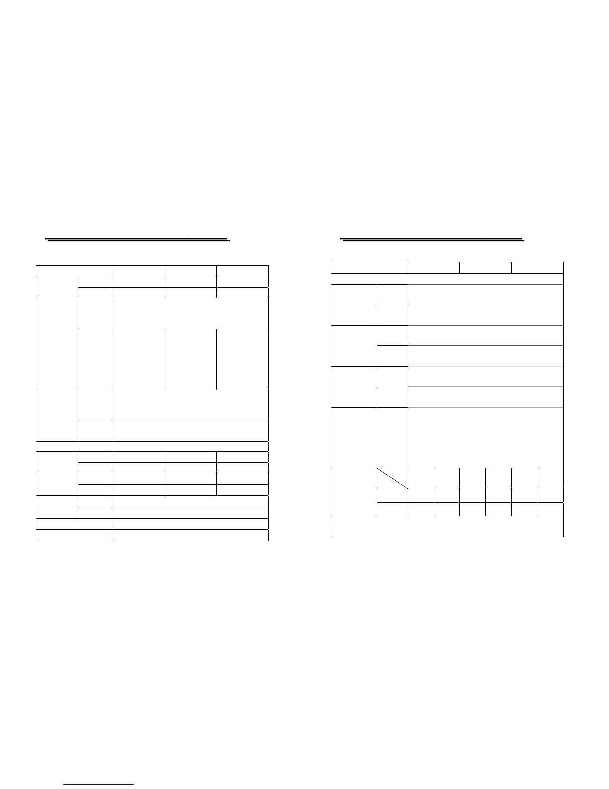
2. TECHNICAL SPECIFICATIONS
Specification PSM-2010 PSM-3004 PSM-6003
Low Range 0~ +8V / 0~20A 0~ +15V / 0~ 7A 0~ +30V / 0~6A
DC Output
High Range 0~ +20V/0~ 10A 0~ +30V/0~4A 0~ +60V/0~3.3A
Regulation
(% output +
offset)
Load regulation ≦ 0.01% + 2mV
Line regulation ≦ 0.01% +2mV
Constant
Voltage
Operation
Ripple &
Noise
<350uVrms/
3mVpp
<350uVrms/
2mVpp
<500uVrms/
3mVpp,
<1mVrms/
3mVpp
(Rating voltage
>50V)
Regulation
(% output +
offset)
Load regulation ≦ 0.01% + 250uA
Line regulation ≦ 0.01% +250uA
Constant
Current
Operation
Ripple &
Noise
2mArms
Resolution
Voltage 1mV 1mV 2mV
Programming
Current 1mA 0.5mA 0.5mA
Voltage 0.5mV 0.5mV 1mV
Readback
Current 1mA 0.1mA 0.5mA
Voltage 1mV
Front Panel
Current 1mA(<10A),10mA(≧ 10A)
OVP 10mV
OCP 10mA
PSM-SERIES PROGRAMMABLE POWER SUPPLY
USER MANUAL
⎯ ⎯
4
Specification PSM-2010 PSM-3004 PSM-6003
Accuracy
Voltage 0.05% + 10mV
Programming
(@23℃±5℃)
,
±(% output
+ offset)
Current 0.2% + 10mA
Voltage 0.05% + 5mV
Readback
(@23℃ ±5℃ ),
±(% output
+ offset)
Current 0.15% + 5mA
Voltage
0.1% + 10mV
OVP/OCP
Accuracy,
±(% output
+ offset)
Current
0.4% + 10mA
Interface Command
proceeding time (The
average proceeding time
during receiving GPIB or
RS-232 command until
voltage output)
100ms
Load
Time
Full
Load
No
Load
Full
Load
No
Load
Full
Load
No
Load
Rise 95ms 45ms 50ms 20ms 80ms 100ms
Voltage Setting
Response Time
(Resistor Load)
Fall 30ms 450ms 45ms 400ms 30ms 450ms
Stability ±(% of output + offset): Following 1 hour warm-up, the output level drift
after 8 hours test under a fixed load, test lead and a mbient te mperat ure.
Page 6
PSM-SERIES PROGRAMMABLE POWER SUPPLY
USER MANUAL
⎯ ⎯
5
Specification PSM-2010 PSM-3004 PSM-6003
Voltage 0.02% + 1mV
Current 0.1% + 1mA
Memory Store/Recall points 0~99
Temperature Coefficient per ℃±(% of output + offset) : Ma ximum cha nge in
output / readback per ℃ after 30-minute warm-up.
Voltage 0.01% + 3mV
Current 0.02% + 3mA
AC Input
100VAC, 120VAC, 220VAC ±10%,
230VAC, –6%+10%, 50/60Hz
Input Rating 700VA, 380W 300VA, 220W 600VA, 310W
Interface RS-232, GPIB
Accessories (1)
Power cord ×1, Instruction manual×1,
Programmer Manual×1
Type
Item
Common terminal
CE Safety
terminal
Test Lead 1 1 set
Sense Lead 0 1 set
Grounding Lead 0 1
Short bar A
on Front panel
3 0
Accessories (2)
Short bar B
on Rear panel
3 3
Operation
Environmental
Indoor use
Altitude up to 2000 m
Ambient temperature:
To satisfy specifications : 10℃~ 35℃( 50° F ~ 95°F )
Maximum operating ranges: 0℃~ 40℃( 32°F ~ 104°F )
Relative humidity: 85% RH (max.) non condensing
Pollution degree: 2
Storage Temperature &
Humidity
-10℃to 70℃, 70%RH (maximum)
Dimensions & Weight 230(W)×140(H)×380(L) mm. Approx. 10kg.
PSM-SERIES PROGRAMMABLE POWER SUPPLY
USER MANUAL
⎯ ⎯
6
3. PRECAUTIONS BEFORE OPERATION
3-1. Unpacking the Instrument
The product has been fully inspected and tested before shipping from the factory.
Upon receiving the instrument, please unpack and inspect it to check if there is
any damage caused during transportation. If any sign of damage is found, notify
the bearer and/or the dealer immediately.
3-2. Checking the Line Voltage
The product can be applied by any kind of line voltages shown in the table below.
Before connecting the power plug to an AC line outlet, make sure the voltage
selector of the rear panel is set to the correct position corresponding to the line
voltage. It might be damaged the instrument by connecting to the wrong AC line
voltage.
WARNING. To avoid electrical shock the power cord protective
grounding conductor must be connected to ground.
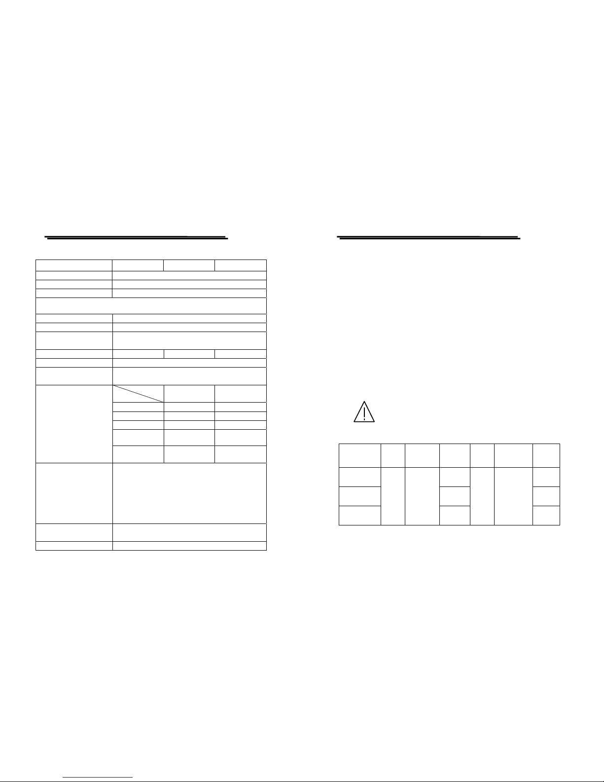
When line voltages are changed, replace the required fuses shown as below:
Model
Line
voltage
Range Fuse
Line
voltage
Range Fuse
PSM-2010
T 7A
250V
T3.15A
250V
PSM-3004
T3.15A
250V
T 1.6A
250V
PSM-6003
100V
120V
90-110V
108-132V
T 5A
250V
220V
230V
198-242V
216-250V
T2.5A
250V
Page 7
PSM-SERIES PROGRAMMABLE POWER SUPPLY
USER MANUAL
⎯ ⎯
7
WARNING. To avoid personal injury, disconnect the power
cord before removing the fuse holder.
3-3. Environment
The normal ambient temperature range of this instrument is from 0° to 40°C (32° to
104°F). To operate the instrument exceeding this specific temperature range may
cause damage to the circuits of instrument.
Do not use the instrument in a place where strong magnetic or electric field exists
as it may disturb the measurement.
CAUTION. To avoid damaging the instrument, do not use it in a
place where ambient temperature exceeds 40℃.
PSM-SERIES PROGRAMMABLE POWER SUPPLY
USER MANUAL
⎯ ⎯
8
4. PANEL INTRODUCTION
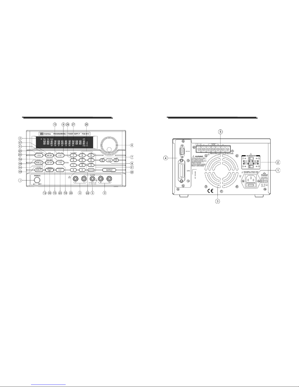
4-1. Front Panel
1. Power Switch
Connect the AC power, then press ON/OFF
power switch.
2. Display
Indicate the setting of voltage/current value,
output voltage/current value and the status of
setting and output.
+Output Terminal Positiv e output terminal.
3.
S+ Output Terminal Positive sampling terminal.
-Output Terminal Negative output terminal.
4.
S- Output Terminal Negative sampling terminal.
5.
GND Terminal Connect the ground terminal to chassis.
6.
Rotary Encoder Wheel knob.
7.
< > Cursor (for value input).
8.
LOCK
A software to lock up panel setting (keep
pressing for a few second).
9.
V SET Output voltage setting.
10.
I SET Output current setting.
11.
OVP SET
Over Voltage protection value setting.
(Level, ON/OFF, Clear)
12.
OCP SET
Over Current Protection value setting.
(Level, ON/OFF, Clear, DELAY)
13.
20V, 10A/8V,20A
Select output voltage /current range (The
secondary function key).
RECALL ⇧ Recall last group of data setting.
Warning. When query the memory setting data, in
order to avoid
personal injury and damaging the
machine, it is suggested to disconnect the output.
14.
RECALL
⇩ Recall next group of data setting.
Page 8
PSM-SERIES PROGRAMMABLE POWER SUPPLY
USER MANUAL
⎯ ⎯
9
15.
DELAY
Set the voltage and current output time in the
automatic operation mode.
16.
AUTO RANGE
(AUTO INFO)
Proceed setting step by step. During setting
proceeding, press this key can display the
memory address of the setting and its residual
time and period (The secondary function key).
17.
AUTO Turn ON/OFF the auto operation.
18.
RECALL
Recall one of the memory datas (The secondary
function key).
When query the memory setting data, in
order to avoid
personal injury and damaging
the machine, it is suggested to disconnect the
output.
19.
STORE
Store the data to one of the memory groups
(The secondary function key).
20.
SHIFT Select the secondary function key.
21.
“0”, “1”… “9”, “.” The key for number input.
22.
ENTER The key for Input confirmation.
23.
LOCAL
Clear the remote control mode by using the
panel control setting instead.
24.
GPIB/RS-232
Select GPIB or RS-232 by pressing [SHIFT]
[GPIB/RS-232].
V STEP
Voltage Step setting (The secondary function
key).
25.
I STEP
Current Step setting (The secondary function
key).
I△
Under the status of [SHIFT], press I△ to
ascend one step of output current value.
I▽
Under the status of [SHIFT], press I▽ to
descend one step of output current value.
V△
Under the status of [SHIFT], press V△ to
ascend one step of output voltage value.
26.
V▽
Under the status of [SHIFT], press V▽ to
descend one step of output voltage value.
PSM-SERIES PROGRAMMABLE POWER SUPPLY
USER MANUAL
⎯ ⎯
10
27.
FL DIMMER
Adjust the intensity of VFD. After pressing
[SHIFT], can press [FL DIMMER] continually
until the required brightness is reached. Then
press again the [SHIFT] to end the setting.
28.
Set beeper by pressing [SHIFT][
] to turn
ON/OFF the buzzer.
29.
OUTPUT Turn on or off output by pressing the knob.
30.
DISPLAY LIMIT
Switch over the voltage and current mode by
pressing [DISPLAY LIMIT].
The setting value will be displayed, press again
[DISPLAY LIMIT] or wait a few seconds to
return to the previous status.
4-2. Rear Panel brief
1. AC Power Socket
AC power input terminal.
2. AC Select Switch
Switch Voltage to 100V, 120V, 220V or 230V,
50/60Hz.
3. Cooling Fan
A cooling fan.
4. Interface
GPIB or RS-232 communication interface.
5. Output Terminal
The output terminals of rear panel connected
with case, including output sampling terminal
and ground terminal.
Page 9
PSM-SERIES PROGRAMMABLE POWER SUPPLY
USER MANUAL
⎯ ⎯
11
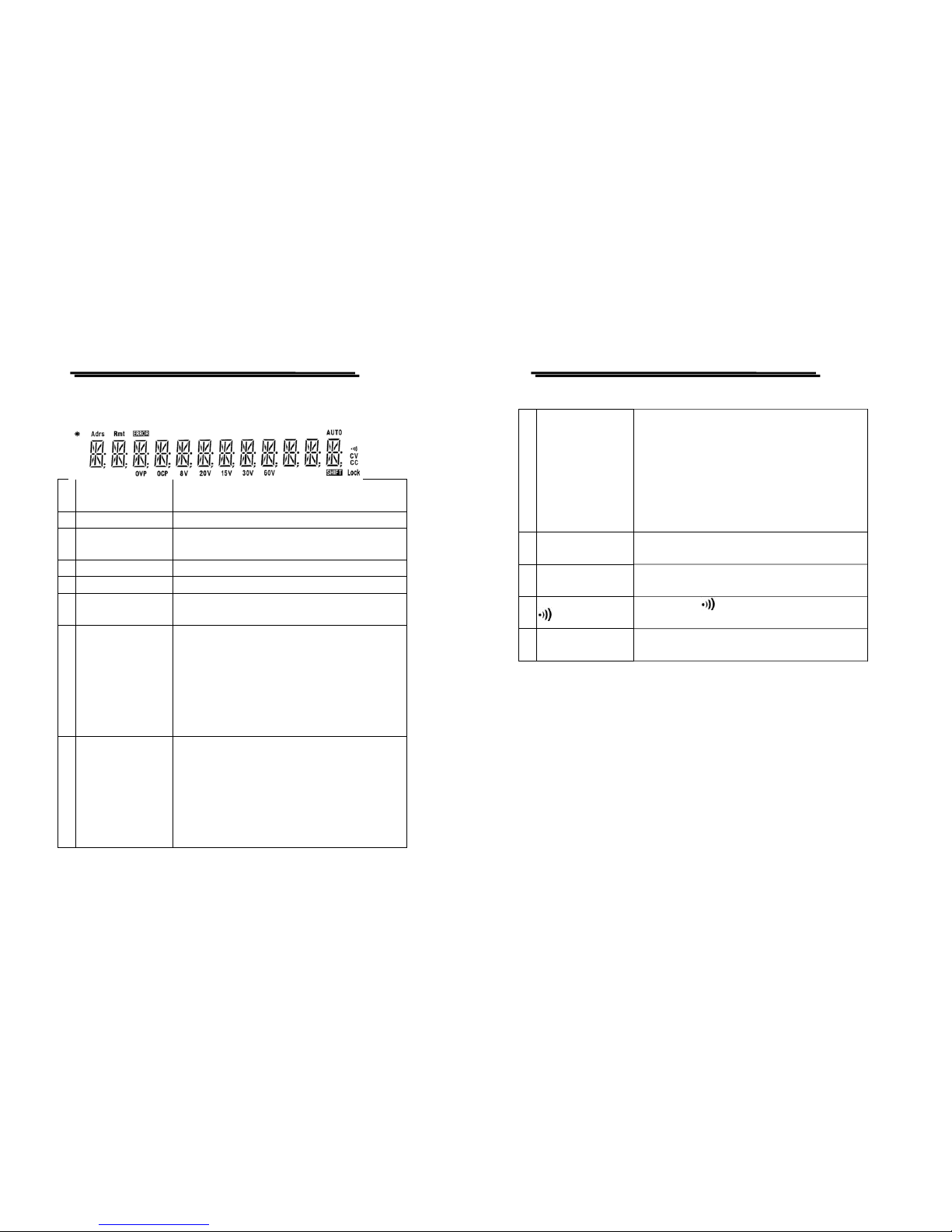
4-3. Display brief
1. Adrs
Set the power sup
p
ly to the address of Listen or
Talk by using the interface card.
2. Rmt Set the power supply to Remote Control mode.
3. ERROR
The Error message appears when the co mmand
from the Remote Controlled Interface is in error.
4. SHIFT Select the second level function.
5. AUTO Set the power supply to Auto mode.
6.
8V, 15V, 20V,
30V, 60V
The output ranges of power supply.
7. OVP
When the indicator lights up without blinking,
means the OVP function is on. When the Over
Voltage Protection function is triggered, the
indicator will be changed to blinking status, and
the message “OVP TRIPPED” will be displayed.
Now clear the OVP function. When the light of
indicator is off, means the OVP function is off.
8. OCP
When the indicator lights up without blinking,
means the OCP function is on. When the Over
Current Protection function is triggered, the
indicator will be changed to blinking status, and
the message “OCP TRIPPED” will be displayed.
N
ow clear the OCP function. When the light of
indicator is off, means the OCP function is off.
PSM-SERIES PROGRAMMABLE POWER SUPPLY
USER MANUAL
⎯ ⎯
12
9.
*
When the power supply is set to operation mode,
the symbol of “ *” will be lighted up.
z When the Output is on, th e symbol of “*”
li
g
hts up to indicate the power supply is in
the operation mode, when the meter
displa
y
s the measurement value, the
symbol of “*” becomes blinking.
10. CC
The CC light is on to indicate the instrument is
in the CC mode.
11. CV
The CV light is on to indicate the instrument is
in the CV mode.
12.
The light of “
” is on to indicate the buzzer is
on.
13. Lock
The Lock light is on to indicate the
p
anel control
knobs is locked up.
Page 10
PSM-SERIES PROGRAMMABLE POWER SUPPLY
USER MANUAL
⎯ ⎯
13
Figure 4-1 Front Panel
PSM-SERIES PROGRAMMABLE POWER SUPPLY
USER MANUAL
⎯ ⎯
14
Figure 4-2 Rear Panel
Page 11

PSM-SERIES PROGRAMMABLE POWER SUPPLY
USER MANUAL
⎯ ⎯
15
5. OPERATION INSTRUCTION
5-1. Basic Operation
z The applied Voltage/Current Unit for this series instruments is Volt and
Amp.
z The Instrument requires 30 minutes warm-up with no load before
operation or calibration to achieve rated accuracy.
z The Factory setting is in panel operation mode that enable user to operate
the instruments directly from panel control knob. Besides, when the
remote controller is on line, the operation can only be proceed through it,
unless the LOCAL key is pressed, at this time, the OUTPUT is still
working. Whenever the power is reset, the output will be at OFF status
and the operation is through front panel operation mode.
z The series of power supplies have double output ranges, after pow er on,
the output is always at OFF status, and the setting is stayed at the
previous setting status before power off.
z Whatever the output is at ON or OFF, the output range can be switched
dynamically. During the switch process, if the original setting value is
more than the maximum output range after switch, the setting value will
be modified automatically to the maximum output value after switch.
z A short plate is attached to the sampling terminal of the front panel,
when use the remote sense, the short plate must be removed.
PSM-SERIES PROGRAMMABLE POWER SUPPLY
USER MANUAL
⎯ ⎯
16
z When the output is set to OFF, the OUTPUT OFF message will be
displayed on the front panel, the setting still can be modified. At the same
time of modification, the corresponding setting item or status will be
displayed. When the output is set to ON, the setting can also be modified.
At the same time of the modification, the panel display mode is changed
from measurement value to the setting item or status. Under the normal
setting of voltage or current, the panel will display measurement value, if
want to change the displayed mode to setting value, press
[SHIFT][DISPLAY LIMIT] to input setting value, after a few seconds, if
no value is input, the display mode will be switched to measurement value
automatically.
z When set output on, the symbol of “*” will be appeared on the upper left
of meter to indicate the instrument is at output mode. when the meter
displays output measurement value(at measuring status), the symbol of
“*” becomes blinking.
5-2. Function Key Description
Press one of the function keys to proceed function setting, after setting,
press again the function key to leave the function or press another key fo r
another setting.
z V SET : Output voltage setting
Page 12
PSM-SERIES PROGRAMMABLE POWER SUPPLY
USER MANUAL
⎯ ⎯
17
The minimum resolution of output voltage is at 1mV. When set output
to ON, press [V SET] to proceed voltage setting, now the meter will
display measurement value (the symbol of “*”is blinking). Besides,
when the operation is set to “DISPLAY LIMIT” mode, the meter will
display setting value (the symbol of “*” lights up without blinking).
When the output is set to OFF, the output voltage setting (V SET) can
be done by pressing [V SET] directly or by changing the “DISPLAY
LIMIT” mode (please refer to the operation of DISPLAY LIMIT).
Setting method 1: Press [V SET][Number key (voltage value)] [ENTER]
to set output voltage.
Setting method 2: Press [V SET][number knob (voltage value)] to
change the output voltage setting immediately, then press again [V SET]
to complete voltage setting. When use this method with the output on,
the input voltage will be changed following the input value by ro tating
the knob which can be adjusted by moving the [<] or [>] cursor.
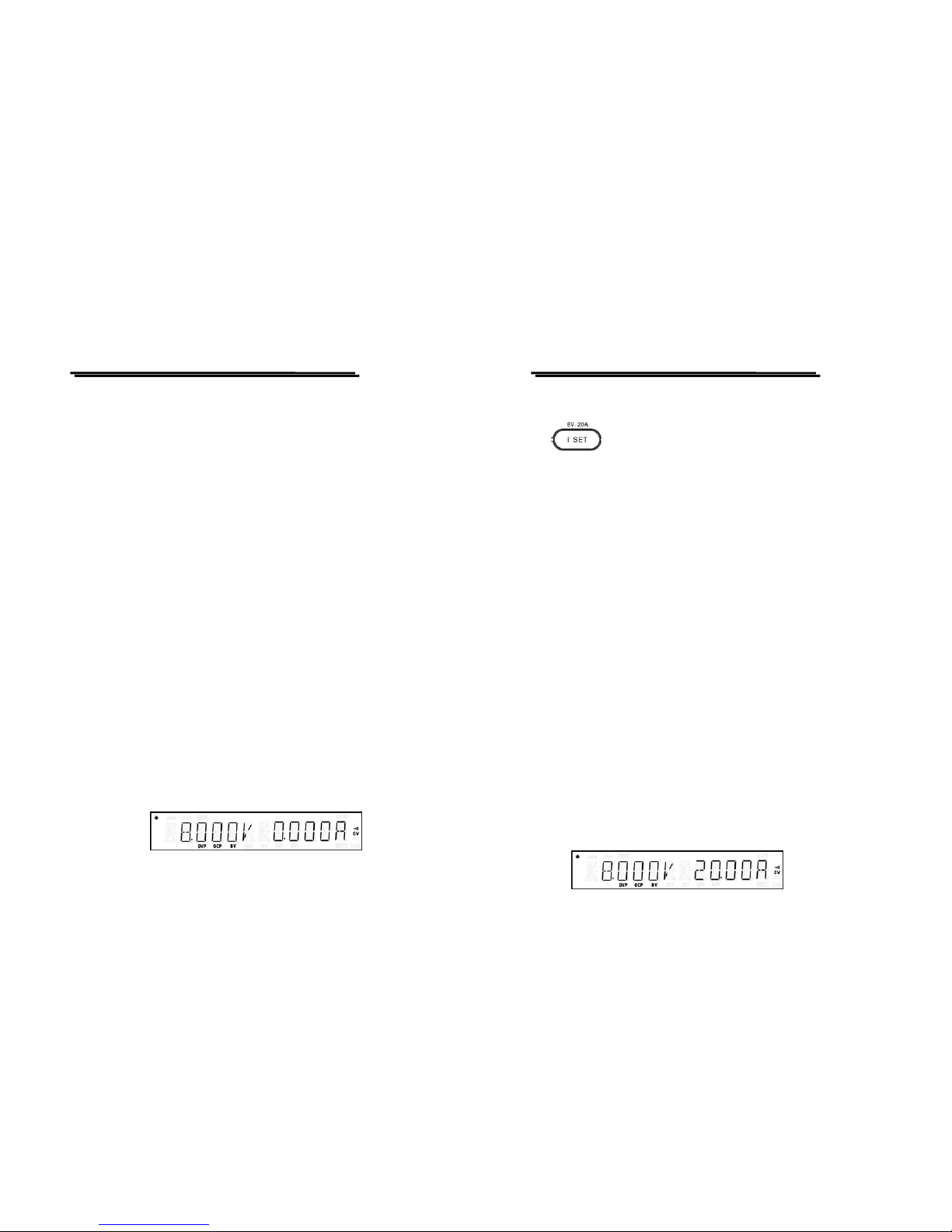
For example: Set output voltage to 8.000V.
Press [V SET][8][.][0][0][0][ENTER] or [V SET][8][ENTER].
PSM-SERIES PROGRAMMABLE POWER SUPPLY
USER MANUAL
⎯ ⎯
18
z I SET : Output current setting
The minimum resolution of output current is at 1mA(output≧ 10A at
10mA). When set output to ON, press [I SET] to proceed current setting,
the meter will display measurement value (the symbol of “*” is on with
blinking). Besides, when the operation is set to “DISPLAY LIMIT”
mode, the meter will display setting value (now the symbol of “*” is on
without blinking). When the output is set to OFF, the output current
setting can be done by pressing [I SET] directly or by changing the
“DISPLAY LIMIT” mode (please refer to the operation of DISPLAY
LIMIT).
Setting method 1: Press [I SET][Number key (current value)] [ENTER]
to set output current.
Setting method 2: Press [I SET][number knob (voltage value)] to change
the output current setting immediately, then press again [I SET] to
complete current setting.。When use this method with the output on, the
input current will be changed following the input value by rotating the
knob which can be adjusted by moving the [<] or [>] cursor.
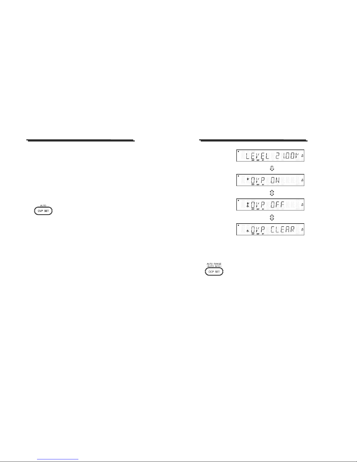
For example: Set output voltage to 20.00A
Press [I SET][2][0][.][0][0][ENTER] or [I SET][2][0][ENTER]
Page 13
PSM-SERIES PROGRAMMABLE POWER SUPPLY
USER MANUAL
⎯ ⎯
19
When the current load runs through output terminal, if the current
exceeds the setting value, the operation of the instrument will be set to
Constant Current Mode (C. C. Mode), if the current does no t exceed the
setting value, the operation will be set to Constant Voltage mode (C. V.
Mode).
z OVP SET: Over Voltage protection setting (LEVEL, ON/OFF
/CLEAR)
Setting method: After pressing [OVP SET], get into Over Voltage
Protection Level setting, now use the number key (or knob) to input
setting value, then press [ENTER] to complete the setting change.
When get into Over Voltage protection state setting by selecting Over
Voltage protection state and pressing [ENTER], use the knob to select
ON/OFF/CLEAR, then press [ENTER] to complete the setting change.
Remark: When the Over Voltage protection of the instrument is
triggered, use the function of Over Voltage Protection
Clear (OVP CLEAR) to clear its prote ction st at e.
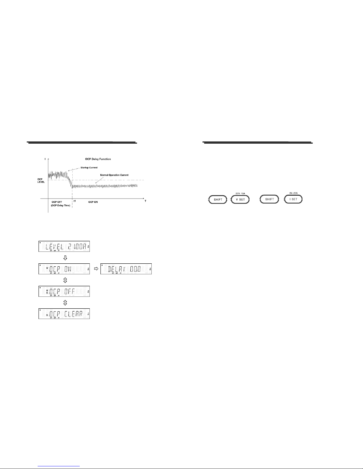
For example: Set Over Voltage protection value to 21.00V at ON state.
After pressing [OVP SET] to get into OVP LEVEL setting, then input
[2][1][.][0][0][ENTER] to get into OVP STATE setting, now set the
knob select state to ON and press [ENTER] to complete setting.
PSM-SERIES PROGRAMMABLE POWER SUPPLY
USER MANUAL
⎯ ⎯
20
z OCP SET: Over current protection setting (LEVEL, ON/OFF/
CLEAR, DELAY)
Setting method: After pressing [OCP SET] to get into Over Current
Protection Level (OCP LEVEL) setting, use the number key (or knob) to
input setting value and press [ENTER] to complete the setting change.
When get into over current protection state, use the knob to select
ON/OFF/CLEAR, then press [ENTER] to change the setting.
When the Over Current Protection is set to ON, then get into Over
Current Protection Delay setting (The minimum Delay time is at 0
second, the maximum is at 10second, and the scale base is 0.1 second).
Page 14
PSM-SERIES PROGRAMMABLE POWER SUPPLY
USER MANUAL
⎯ ⎯
21
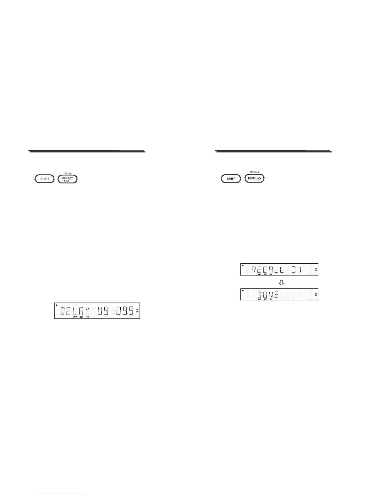
z OCP DELAY TIME CHART
Remark: When the over current protection of the instrument is
triggered, use the function of Over Current Protection
Clear (OCP CLEAR) to clear its prote ction st at e.
PSM-SERIES PROGRAMMABLE POWER SUPPLY
USER MANUAL
⎯ ⎯
22
For example: Set over current protection value to 21.00A at ON state.
After pressing [OCP SET], get into OCP LEVEL setting, input
[2][1][.][0][0][ENTER], now set the knob select state to ON and press
[ENTER] to complete setting.
z Output voltage/current selection
When re-power on, the output range is stayed at the previous setting
before power off. Besides, whatever the output is at ON or OFF status,
the output range can be switched over dynamically. When the setting
value is more than the value of the switched voltage/current range, it
will be modified to maximum value of the switched range automatically.
If the setting value is less than the value of the switched voltage/current
range, it will be stayed as it is.
z PSM-2010 :20V,10A /8V,20A
z PSM-3004 :30V,4A/15V,7A
z PSM-6003 :60V,3.3A/30V,6A
For example: Set output range of PSM-2010 to 20V, 10A
Press [SHIFT][20V,10A], the output range will be changed to 20V,10A.
Page 15
PSM-SERIES PROGRAMMABLE POWER SUPPLY
USER MANUAL
⎯ ⎯
23
z DELAY : The Auto mode setting for the voltage/current Delay time
Setting method: Press [SHIFT] [DELAY] to appear the “MIN.” setting item
selection, then input setting value and press [ENTER] to “SEC.” setting
item selection, input setting value and press [ENTER] to change Delay
setting.
Remark:
1) The minimum unit of the “SEC.” Setting picture is at 0.1 sec.
2) The Delay setting is effective only under the Auto running
operation, therefore, during the storage proceeding, the Delay
setting will be saved to the memory address simultaneously.
For example: Set the Delay time to 9 minutes and 9.9 seconds.
Press [SHIFT] [DELAY] to appear “MIN” setting item, input [9] and
[ENTER], then select “SEC” setting item and input [9][.][9][ENTER] to
complete DELAY setting.
PSM-SERIES PROGRAMMABLE POWER SUPPLY
USER MANUAL
⎯ ⎯
24
z RECALL : Recall the setting data from the memory bank
Remark:
1) After RECALL setting, it needs to press again [SHIFT]
[RECALL] to leave the function.
2) When query the stored setting data, in order to avoid personal
injury and damaging the machine, it is suggested to turn off
the output.
Recall Setting method: Press [SHIFT][RECALL](Recall Data setting
from the memory bank), use knob or number key to input the memory
address.
For example: Recall the setting data from the memory address of 01.
Press [SHIFT][RECALL], get into RECALL setting, then press
[0][1][ENTER] to complete Recall.
Page 16
PSM-SERIES PROGRAMMABLE POWER SUPPLY
USER MANUAL
⎯ ⎯
25
z AUTO RANGE
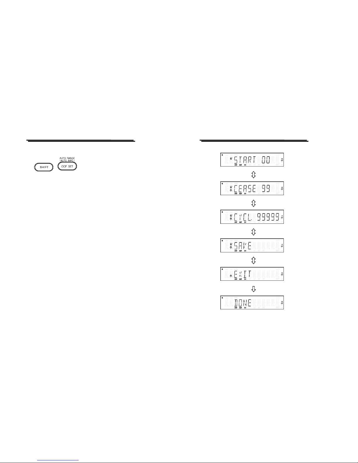
AUTO RANGE Setting method: Press [SHIFT][AUTO RANGE] , use
knob to select the item for setting change.
For example: Set the AUTO RANGE to: START : 00 ; CEASE : 99 ;
CYCLE : 99999。
Press [SHIFT][AOTU RANGE] to enter AUTO RANGE setting item
selection, first select START and press [ENTER], then input [0][0]
[ENTER] to complete the change. Then input [9][9][ENTER] to CEASE
setting item to complete CEASE setting. Furthermore, input [9][9][9][9][9]
[ENTER] to CYCLE setting item to complete CYCLE setting. After
proceeding above setting, select SAVE to store the setting or select EXIT
to exit the setting with ou t sto ring .
PSM-SERIES PROGRAMMABLE POWER SUPPLY
USER MANUAL
⎯ ⎯
26
Page 17
PSM-SERIES PROGRAMMABLE POWER SUPPLY
USER MANUAL
⎯ ⎯
27
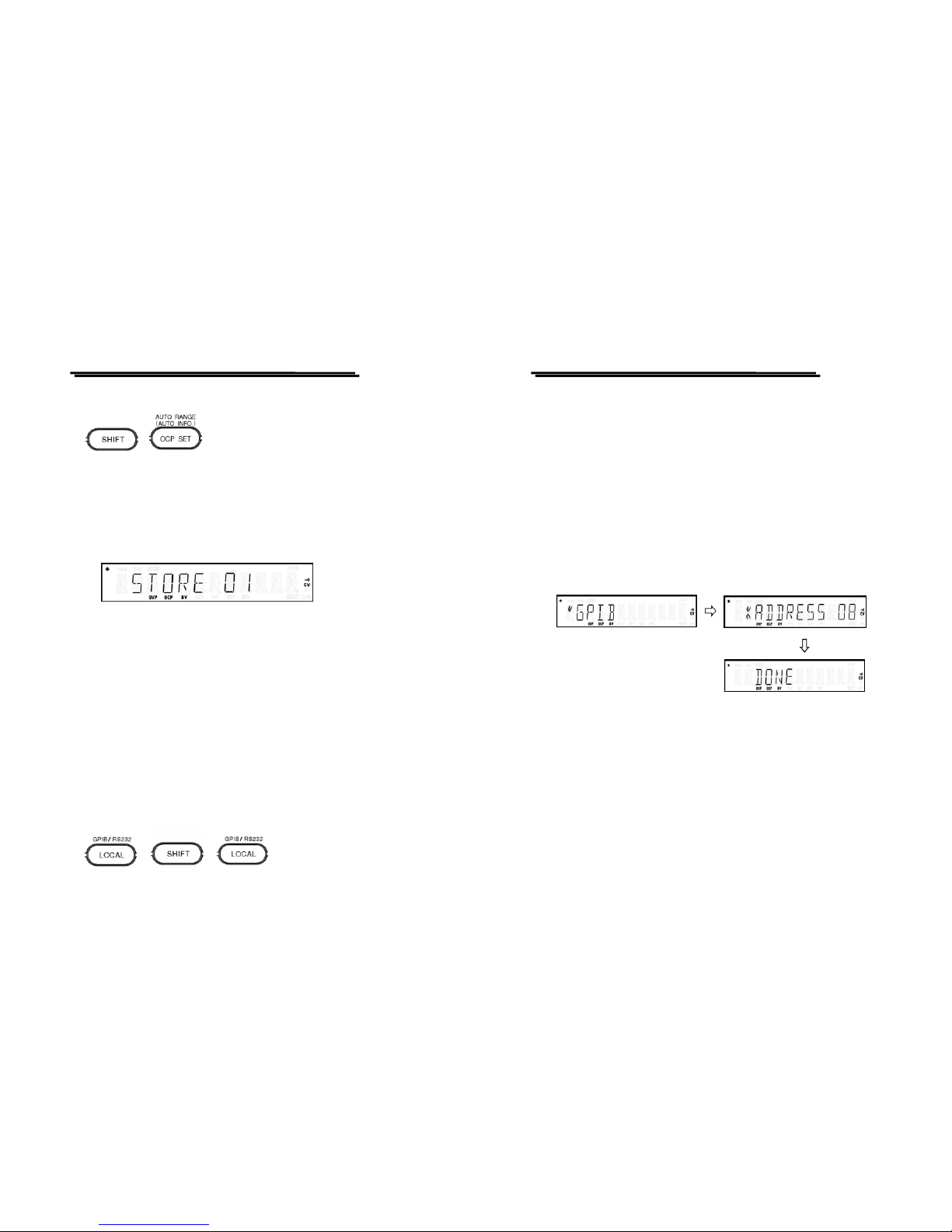
z STORE : Save the setting data to one of the memory groups
STORE setting method: Press the function of [STORE], use knob or
number key to input the memory address to save the data.
For example: Store the setting date to the memory address of 01.
Press [SHIFT][STORE] to get into STORE setting, then input
[0][1][ENTER] to complete the Store.
z Rotary Encoder : The wheel knob for number input or function
selection.
The function knob can be used for number input or function selection.
When the knob is used as number input, it should be matched with the
cursor moving keys [<] and [>].
z [<] and [>]: [<] and [>] are cursor moving keys for number input or
function selection.
z LOCAL(GPI B/RS-232 ) : Clear the Remot e Cont rol mode an d use t he
panel control mode instead. Press [SHIFT][GPIB/RS-232] to GPIB
or RS-232 setting selection.
PSM-SERIES PROGRAMMABLE POWER SUPPLY
USER MANUAL
⎯ ⎯
28
Press [LOCAL] function can clear Remote Control mode and use panel
control instead. After press [SHIFT][GPIB/RS-232], use knob to select
GPIB or RS-232 and press [ENTER] to confirm the setting. If want to set
to GPIB, use knob to select input address, then press [ENTER] to
complete GPIB setting. If want to set to RS-232, use knob to select input
BAUD rate, then press [ENTER] to complete RS-232 setting.
Remark: When enter GPIB/RS-232 setting, can press again [SHIFT]
[GPIB/RS-232] to leave the function.
For example: Select GPIB communication interface and set the
ADDRESS to 08.
Press [SHIFT] [GPIB/RS-232], use wheel knob to select GPIB and press
[ENTER] to confirm the setting. Then use wheel knob to select [08] and
press [ENTER] to complete GPIB setting.
Page 18
PSM-SERIES PROGRAMMABLE POWER SUPPLY
USER MANUAL
⎯ ⎯
29
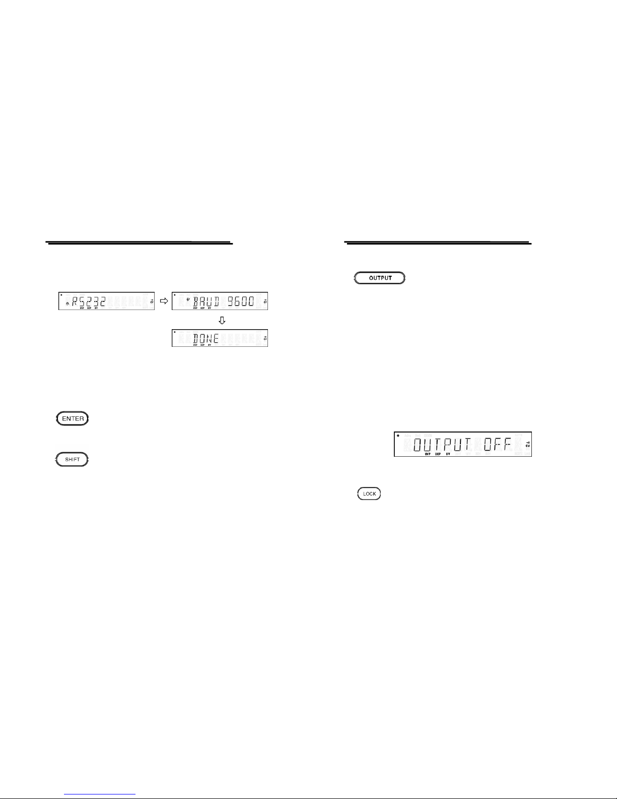
For example: Select RS-232 communication interface and set the BAUD
rate to 9600.
Press [SHIFT] [GPIB/RS-232], use wheel knob to select RS-232 and
press [ENTER] to confirm the setting. Then use wheel knob to select
[9600] and press [ENTER] to complete RS-232 setting.
z ENTER : The key for input confirmation.
z SHIFT : The push- butto n to s elect the s econd leve l func tion.
PSM-SERIES PROGRAMMABLE POWER SUPPLY
USER MANUAL
⎯ ⎯
30
z OUTPUT : Turn on/off the output
When the output is set to OFF, the OUTPUT OFF message will be
displayed on the front panel, and the CC and CV indicators are off, but
the rest of indicators keep at the original setting. When Output is on, the
symbol of “*” at the upper left corner of the panel will be on to indicate
the power supply is in the output mode, when the meter displays the
measurement value, the symbol of “*” becomes blinking (the symbol of
“*” is on without blinking when the display other than the measurement
value). When the instrument is operated in the CV mode, the CV
indicator is on, while in the CC mode, the CC indicator is on.
z LOCK : The key to lock up panel setting.
Press the LOCK key to lock up the panel setting, now, the Output key is
still working. Press the key again for several seconds to unlock the panel
setting.
Page 19
PSM-SERIES PROGRAMMABLE POWER SUPPLY
USER MANUAL
⎯ ⎯
31
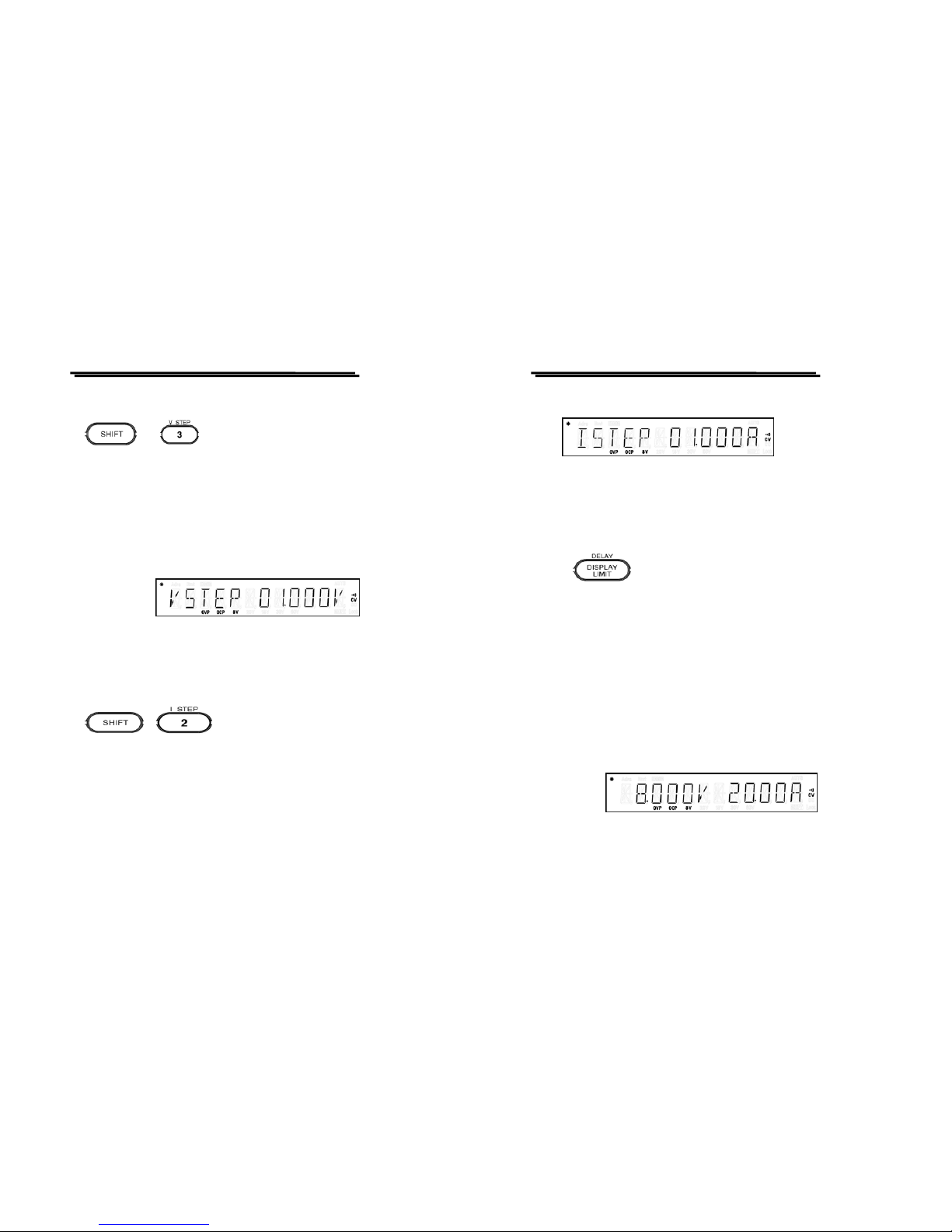
z V STEP : The step setting of voltage.
Set the maximum value of Step to be the rating value of the setting
range.
Switch to “V STEP” by pressing [SHIFT][V STEP], use number key (or
knob) to input setting value, then press [ENTER] to complete and store
the voltage step setting.
For example: Set the “V STEP” to 1.000V.
Press [SHIFT] [V STEP], then input [1][.][0][0][0][ENTER] to
complete and store the voltage step setting.
z I STEP : The st ep s ett ing of curr ent.
Set the maximum value of Step to be the rating value of the setting
range.
Switch to “I STEP” by pressing [SHIFT][I STEP], use number key (or
knob) to input setting value, then press [ENTER] to complete and store
the current step setting.
PSM-SERIES PROGRAMMABLE POWER SUPPLY
USER MANUAL
⎯ ⎯
32
For example: Set the “I STEP” to 1.000A.
Press [SHIFT] [I STEP], then input [1][.][0][0][0][ENTER] to complete
and store the current step se ttin g.
z DISPLAY LI MIT : S wit ch pa nel dis pla y to the vo ltage /cu rrent
setting mode.
Display the present voltage and curren t value, this func tion can be
operated both on Output on and off.
Switch to the voltage/current setting mode by pressing [DISPLAY
LIMIT], then press again [DISPLAY LIMIT] for several seconds to leave
the setting mode and back to the measure ment mode or “OUTP UT OFF”.
The operation of the voltage/current setting can be matched with the [V
SET] or [I SET] to ch ange the outpu t value. When set the outpu t to ON,
the change of value will be reacted to the output immediately.
Page 20

PSM-SERIES PROGRAMMABLE POWER SUPPLY
USER MANUAL
⎯ ⎯
33
5-3. Operation Method
The applied Voltage/Current Unit for this series instruments is Volt and
Amp.
z Constant Voltage Operation
1) Connect load to output t ermi nal :
For the safety, when connec t the load to output termin als of (+)
and (-), it must turn off the power.
2) Select output range:
Turn on the power after the load is well connected, select the
adequate operation range by pressing [SHIFT][8V/20A] or
[SHIFT][20V/10A]).
3) Set the current limit value:
Press [I SET], the panel operation is set to curr ent value input
mode, set the desired change value by using the number key or
the wheel knobs (the wheel knob can be used together with [<] or
[>] to adjust the resolution).
4) Set the desired output voltage value:
Press [V SET], the panel operation is set to voltag e value input
mode, change to the desired value by using the number key or
the wheel knobs (the wheel knob can be used together with [<] or
[>] to adjust the resolution).
PSM-SERIES PROGRAMMABLE POWER SUPPLY
USER MANUAL
⎯ ⎯
34
5) Star t th e ou tput :
Press [OUTPUT] to enable output, now, the meter displays the
actual output measurement value.
6) Constant voltage mode confirmation
Check whether the C.V. indicator is on or not to make sure the
output operation is under the constant voltage mode. If the C.C.
indicator is on, it needs to enlarge its current limit value to assure
that the output operation is under constant voltage mode.
z Constant Current Operation
1) Connect load to output t ermi nal :
For the safety, when connec t the load to output termin als of (+)
and (-), it must turn off the power.
2) Select output range:
Turn on the power after the load is well connected, select the
adequate operation range by pressing [SHIFT][8V/20A] or
[SHIFT][20V/10A]).
3) Set the voltage limit value:
Press [V SET], the panel operation is set to voltage value input
mode, set the desired change value by using the number key or
the wheel knobs (the wheel knob can be used together with [<] or
[>] to adjust the resolution.
Page 21

PSM-SERIES PROGRAMMABLE POWER SUPPLY
USER MANUAL
⎯ ⎯
35
4) Set the desired output current value:
Press [I SET], the pane l operation is set to current value in put
mode, change to the desired value by using the number key or
the wheel knobs (the wheel knob can be used together with [<] or
[>] to adjust the resolution.
5) Star t th e ou tput :
Press [OUTPUT] to enable output, now, the meter displays the
actual output measurement value.
6) Constant current mode confirmation
Check whether the C.C. indicator is on or not to make sure the
output operation is under the constant current mode. If the C.V.
indicator is on, it needs to enlarge its voltage limit value to
assure that the output operation is under constant current mode.
z Programming Over Voltage Protection, OVP
Set OVP level and the protection circuit of the OVP status.
1) Input the value of the Over Voltage protection limit value and set
the OVP status.
2) Confirm the function of OVP (Over Voltage Protection):
Adjust the output voltage up near to OVP level to confirm the
OVP function, when the OVP circuit is triggered, the OVP loop
will drop the output voltage near to zero, now, the OVP indicator
will be blinking.
3) Clear the OVP function:
PSM-SERIES PROGRAMMABLE POWER SUPPLY
USER MANUAL
⎯ ⎯
36
Firstly, remove the external test unit, such as battery, from the
instrument, adjust the voltage down or raise up the OVP level,
then clear the OVP.
z Programming Over Current Protection, OCP
Set OCP level and the protection circuit of the OCP status.
1) Input the value of the Over Voltage protection limit value and se t
the OCP status.
2) Confirm the function of OCP (Over Current Protection):
Adjust the output current up near to OCP level to confirm t he
OCP function, when the OCP circuit is triggered, the OCP loop
will drop the output current near to zero, now, the OCP indicator
will be blinking.
3) Clear the OCP function:
Firstly, remove the external test unit, such as battery, from the
instrument, adjust the output current down or raise up the OCP
level, then clear the OCP.
z Storing and Recalling Operating:
1) The storing setting function including the store of the Output
range, Output voltage value, Output current value, Ov er Voltage
protection level, Over Current protection level, Over Voltage
protection status, Over Current protection status and the Delay
time.
Page 22

PSM-SERIES PROGRAMMABLE POWER SUPPLY
USER MANUAL
⎯ ⎯
37
2) Store the present setting status to the memory bank:
Press [SHIFT][STORE], set the panel operation to Storing setting
selection, input the memory address by using number key (When
want to correct the input value due to error key- in, can use whee l
knob to clear the error value and re-input the value), then press
[ENTER] to complete the change of store, and the panel will
display “DONE” message.
3) Recall the setting status from the memory bank:
Press [SHIFT][RECALL], set the panel operation to Recall
setting, use the number key to recall the desired memory address
(When want to correct the input value due to error key-in, can
use wheel knob to clear the error value and re-input the value),
then press [ENTER] to complete the change, and the panel will
display “DONE” message.
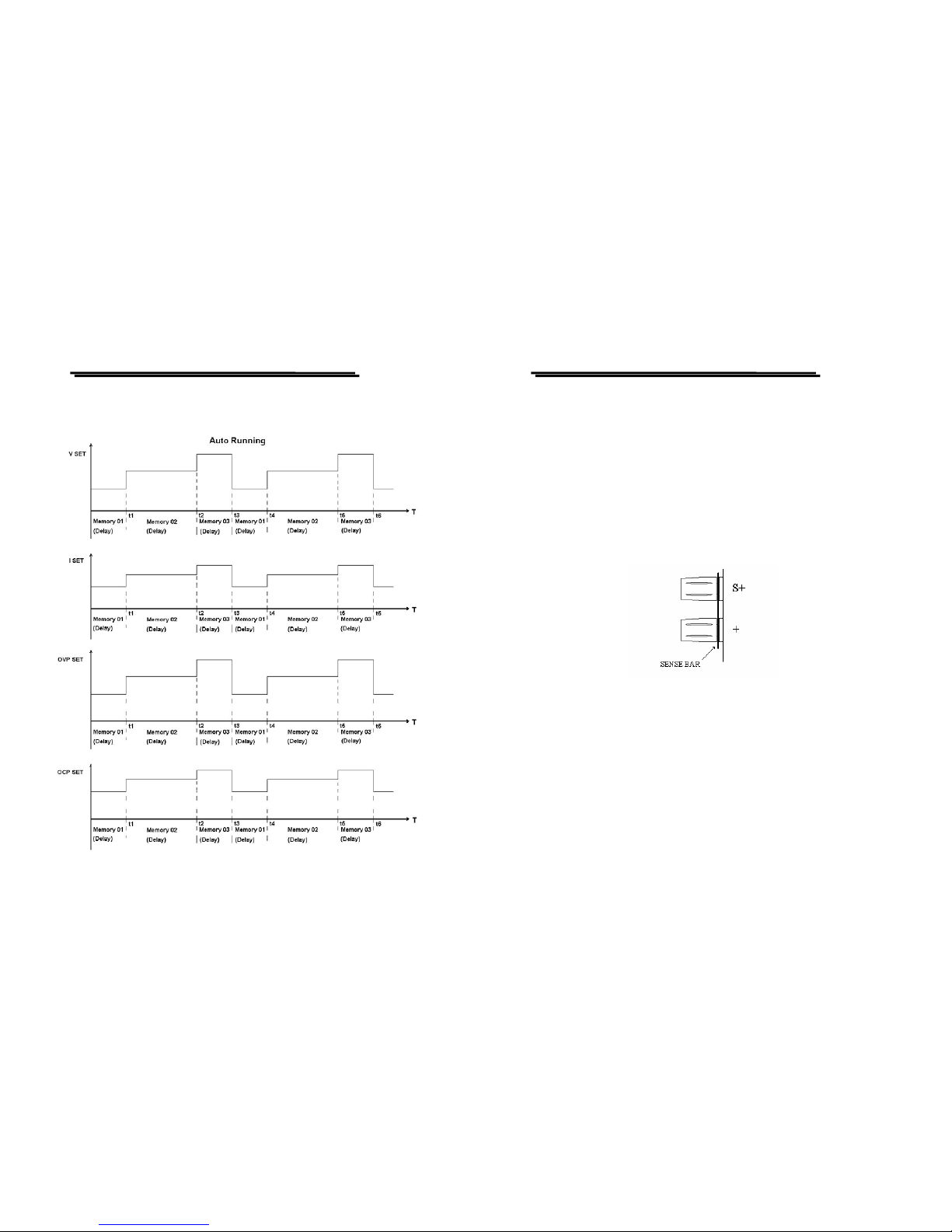
z Auto Running Operation
The function must be used together with the DELAY setting which
is defined as the operation delay time of next running operation. The
Delay function is workable only under Auto Running operation.
1) Delay time setting:
Press [DELAY] to set the panel operation to Delay time setting
selection.
PSM-SERIES PROGRAMMABLE POWER SUPPLY
USER MANUAL
⎯ ⎯
38
2) The setting and stor e of v ery group of data:
A group setting includes the Output range, Output voltage value,
Output current value, Over Voltage protection level, Over
Current protection level, Over Voltage status (ON/OFF), and
Delay time. User can proceed the setting and store it to the
memory bank group by group up to 100 groups maximum.
3) Recall range setting (Auto runn ing operation r ange):
Regarding the setting description, please refer to AUTO RANGE
operation.
4) Enter AUTO mode by pressing [AUTO], now, the operation is in
the auto running function by pressing [OUTPUT].
5) Under this mode, press [SHIFT][AUTO INFO] can monitor the
current operation setting address and operation time.
Page 23
PSM-SERIES PROGRAMMABLE POWER SUPPLY
USER MANUAL
⎯ ⎯
39
z The flow chart of the Auto Running Operation
PSM-SERIES PROGRAMMABLE POWER SUPPLY
USER MANUAL
⎯ ⎯
40
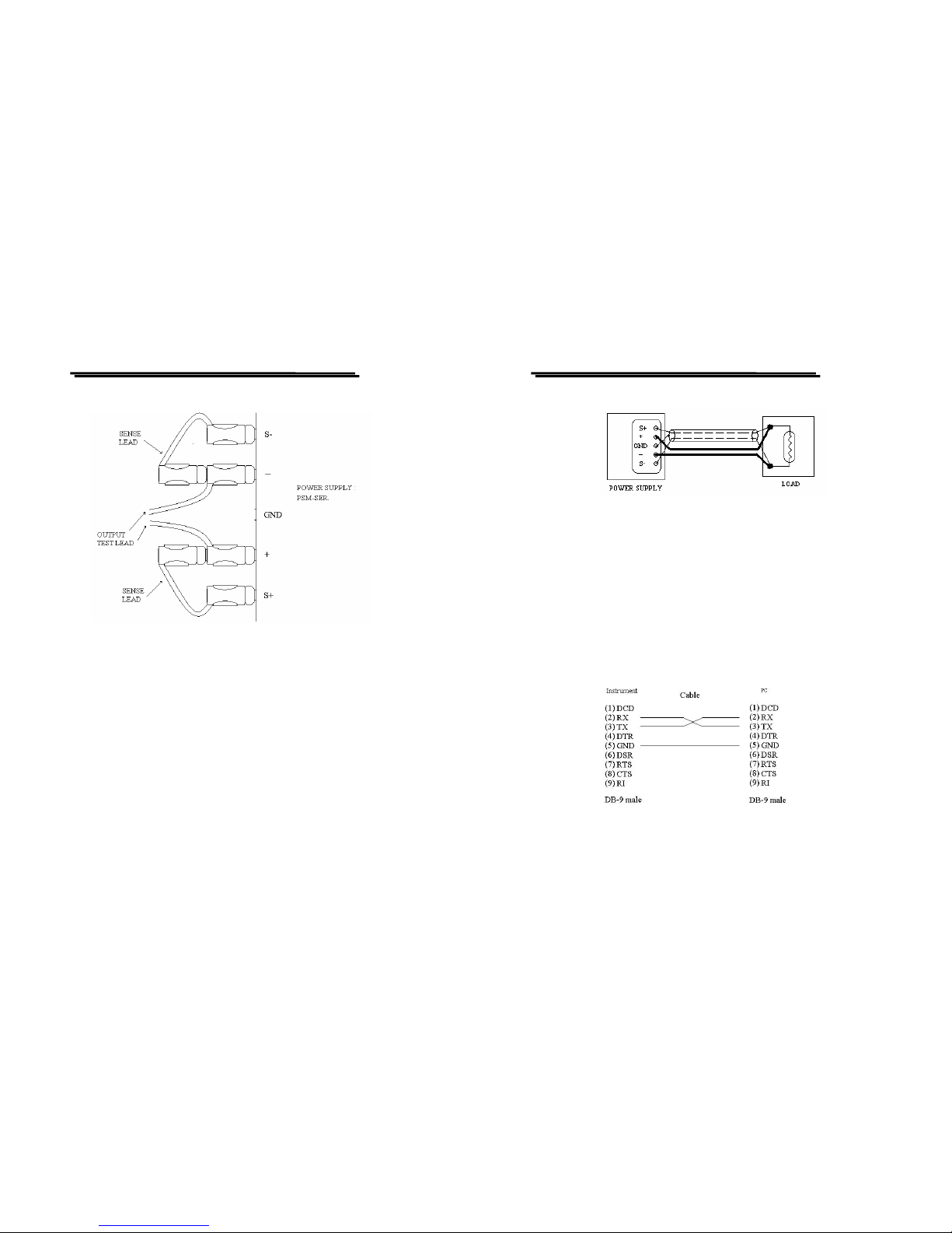
z The Remote voltage sensing of the front/rear panel terminals:
The remote voltage sensing circuit is to compensate the voltage drop
occurred on the power supply and load termin al during load adding.
When proceed the remote voltage sensing, the probe connected
between the output of power supply and the sensing terminal must
be removed. The output terminals of the front panel and rear panel is
parallel and connected with the sensing terminal, when use the
output of front panel, the sensing probe of the rear panel terminal
must be removed, and visa versa.
Figure 5-1:General output terminal sampling and output wiring
Page 24
PSM-SERIES PROGRAMMABLE POWER SUPPLY
USER MANUAL
⎯ ⎯
41
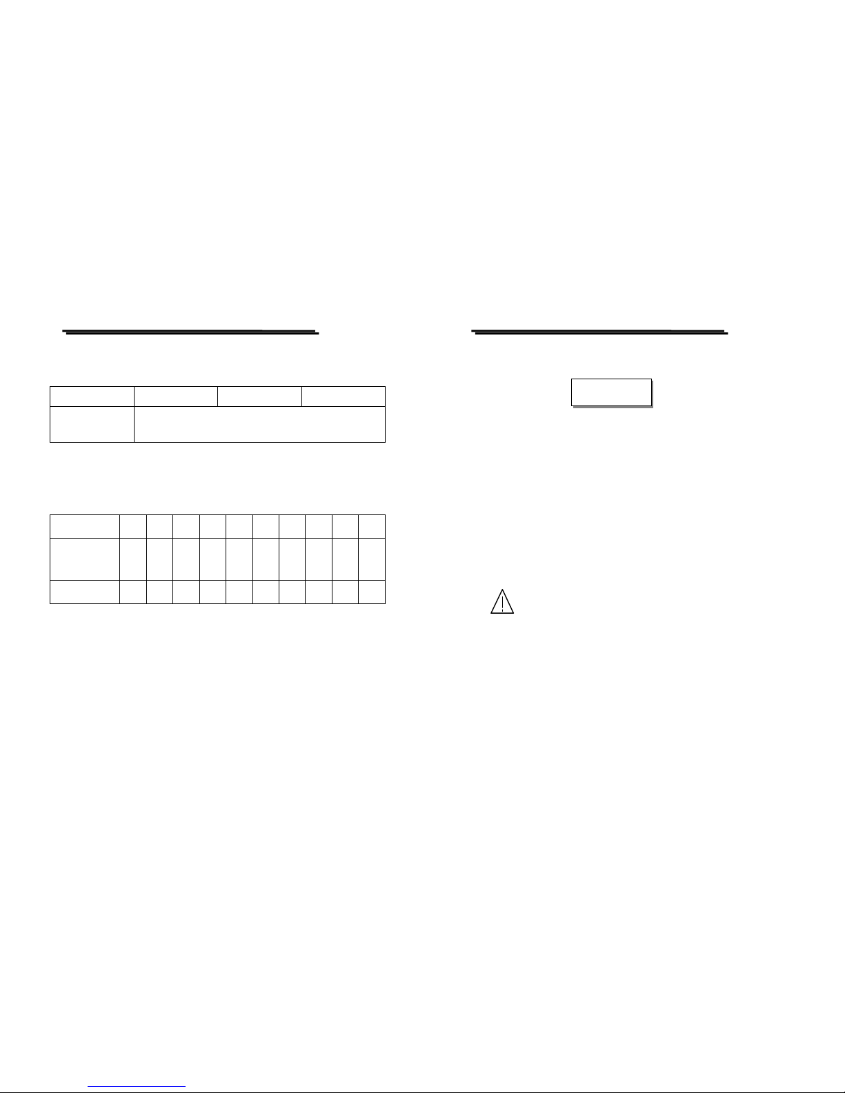
Figure 5-2: Sampling and wiring application for the output terminal of
European Regulation
1) CV Regulation
When the voltage drop between the (+) output terminal and positive
sensing point increases 1V, its voltage Load regulation must be add
another 5mV.
2) Output Noise
A voltage load regulation effects could be occurred by any noise
which interferes the output terminal of the power supply. Therefore,
it will be helpful to reduce the output noise by paralleling two
sensing circuit of (S+) and (S-) and separating each other adequately,
then connect a single end to the ground terminal of power supply.
PSM-SERIES PROGRAMMABLE POWER SUPPLY
USER MANUAL
⎯ ⎯
42
The relative configuration is as follows:
Figure 5-3
z Panel Lock Key:
Press [LOCK] key can lock up the panel control knob to prevent any
setting change, now the [OUTPUT] key still works. Press again
[LOCK] key for a few seconds can release the lock setting.
z GPIB and RS232 interface setting:
Please refer to the PSM-SERIES Programmer manual for detailed
description.
RS232 cable configuration:
Figure 5-4 RS-232 Cable Configuration
Please enter to our web site for updated information:
Page 25

PSM-SERIES PROGRAMMABLE POWER SUPPLY
USER MANUAL
⎯ ⎯
43
http://www.goodwill.com.tw
PSM-SERIES PROGRAMMABLE POWER SUPPLY
USER MANUAL
⎯ ⎯
44
5-4. The maximum value of the output setting
Model
PSM-2010 PSM-3004 PSM-6003
Output Range
Item
8V,20A 20V,10A 15V,7A 30V,4A 30V,6A 60V,3.3A
Output Voltage 8.240V 20.60V 15.450V 30.900V 30.900V 61.800V
Output Current 20.60A 10.30A 7.210A 4.120A 6.180A 3.400A
OVP (Over Voltage
Protection
22V 32V 64V
OCP (Over Current
Protection
22A 7.500A 6.500A
Step Voltage 8.000V 20.000V 15.000V 30.000V 30.000V 60.000V
Step Current 20.00A 10.00A 7.000A 4.000A 6.000A 3.300A
Delay Time 99’59”
Memory Group 100
Page 26
PSM-SERIES PROGRAMMABLE POWER SUPPLY
USER MANUAL
⎯ ⎯
45
5-5. Test Lead
Table 1:
Model PSM-2010 PSM-3004 PSM-6003
Test Lead
GTL-104 or GTL-204
(The maximum current: 10A)
Note: The attached test lead to the PSM-SERIES is only used for the front
panel output terminal with the maximum current of 10A.
Table (2)
AWG
10 12 14 16 18 20 22 24 26 28
Maximum
Current(amps)
40 25 20 13 10 7 5 3.5 2.5 1.7
mΩ /m
3.3 5.2 8.3 13.2 21.0 33.5 52.8 84.3 133.9 212.9
PSM-SERIES PROGRAMMABLE POWER SUPPLY
USER MANUAL
⎯ ⎯
46
6. MAINTENANCE
The following instructions are executed by qualified personnel only. To
avoid electrical shock, do no perform any servicing other than the operating
instructions unless you are qualified to do so.
6-1. Fuse Replacement
If the fuse blows, the display will not light and the power supply will not
operate. The fuse should not normally open unless a problem has
developed in the unit. Try to determine and correct the cause of the blown
fuse, then replace only with a fuse of the correct rating and type.
WARNING. For continued fire protection. Replace fuse
only with 250V fuse of the specific type and rating, and
disconnect power cord before replacing fus e.
6-2. Line Voltage Conversion
The primary winding of the power transformer is tapped to permit
operation from 100, 120, 220, or 230VAC, 50/60 Hz line voltage.
Conversion from one line voltage to another is done by change AC
selects switch.
The rear panel identifies the line voltage to which the unit was factory
set. To convert to a different line voltage, perform the following
procedure:
WARNING
Page 27
PSM-SERIES PROGRAMMABLE POWER SUPPLY
USER MANUAL
⎯ ⎯
47
(1) Make sure the power cord is unplugged.
(2) Change the AC selects switch to the desired line voltage position.
A change in line voltage may also require a corresponding change of
fuse value. Install the correct fuse value as listed on rear panel.
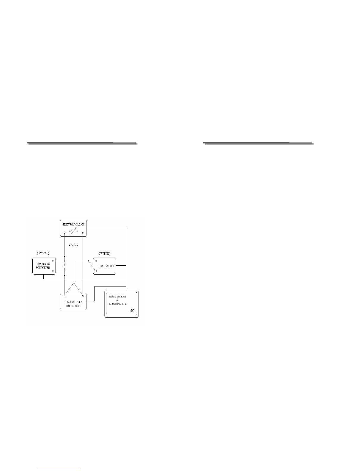
6-3. Measurement Techniques
For an accurate and convenient measure ment, ple ase set up th e instrumen t
according to the following:
1) Setup:
Figure 6-1
PSM-SERIES PROGRAMMABLE POWER SUPPLY
USER MANUAL
⎯ ⎯
48
2) The calibrated devices:
For general calibration, user can select the suitable calibration devices
by their own. Please refer to the below recommendation:
A. Electronic Load
In order to meet the demand of the auto calibration, the Electronic
Load with GPIB is well recommended. The main function of the
Electronic Load is to control the short test (CC current calibration),
the connection test (voltage load regulation, transient response
time) and open test( CV voltage calibration).
Measurement Techniques
Assure a precise Load regulation, Voltage peak to peak, and
transient response time, the test joint point must be configured to
sampling terminals of S+ and S-.
B. Current Monitoring Resistor
The resistor must have sufficient Watt value that can meet the
calibration need to control the change amount less than 15mA
when a 20.00A current run over it for a long period.
C. DVM or RMS Voltmeter
The meter used for the output voltage measurement should have
0.1mV resolution (accuracy: 0.01%). For the output current
measurement, the meter should have 0.001mV resolution(accuracy:
0.01%) to measure th e voltage of the shunt, then transfer it to the
corresponding current value.
Page 28
PSM-SERIES PROGRAMMABLE POWER SUPPLY
USER MANUAL
⎯ ⎯
49
D. Oscilloscope
To test the voltage noise and output oscillator when the power supply
is in the CV and CC mode.
E. Person Computer (PC)
This is a supplementary tool for the auto calibration including interface
card and auto calibration software of its own.
PSM-SERIES PROGRAMMABLE POWER SUPPLY
USER MANUAL
⎯ ⎯
50
6-4. Adjustment and Calibration
--Preparation
1. 30 minutes warm up before calibration.
2. Ambient temperature :23±5°C, Humidity: Under RH80%.
--Output Calibration Steps:
[Step 1]
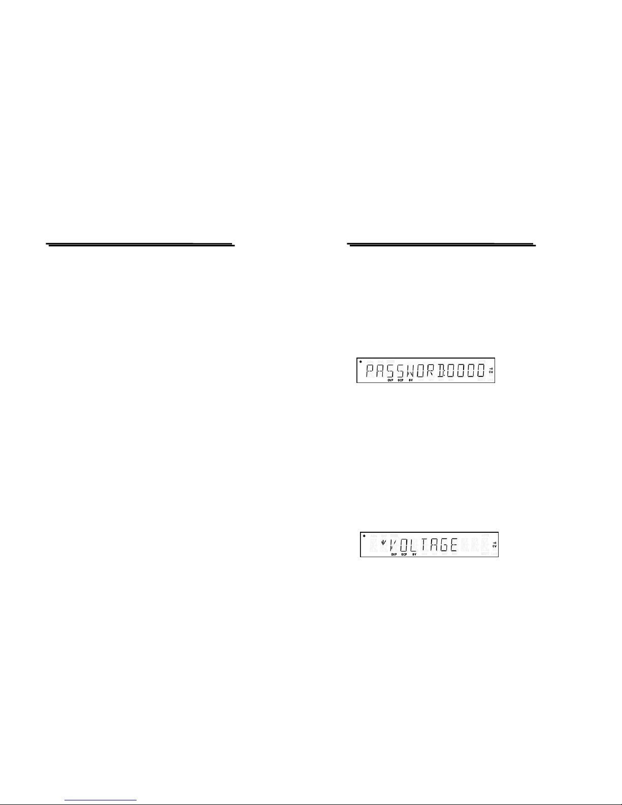
Press [SHIFT][ .] to appear Password input window, input Password (vary
with different models: PSM-2010= 2010, PSM-3004 = 3004, PSM-6003 =
6003) by using the number key, press [ENTER] key
[Step 2]
When get into Calibrated item selection window, set the cursor to the
calibrated item by using the knob and press [ENTER]. After the calibrated
item is selected, proceeding voltage, current and over-voltage calibration
step by step.
[Step 3] Voltage Calibration Steps
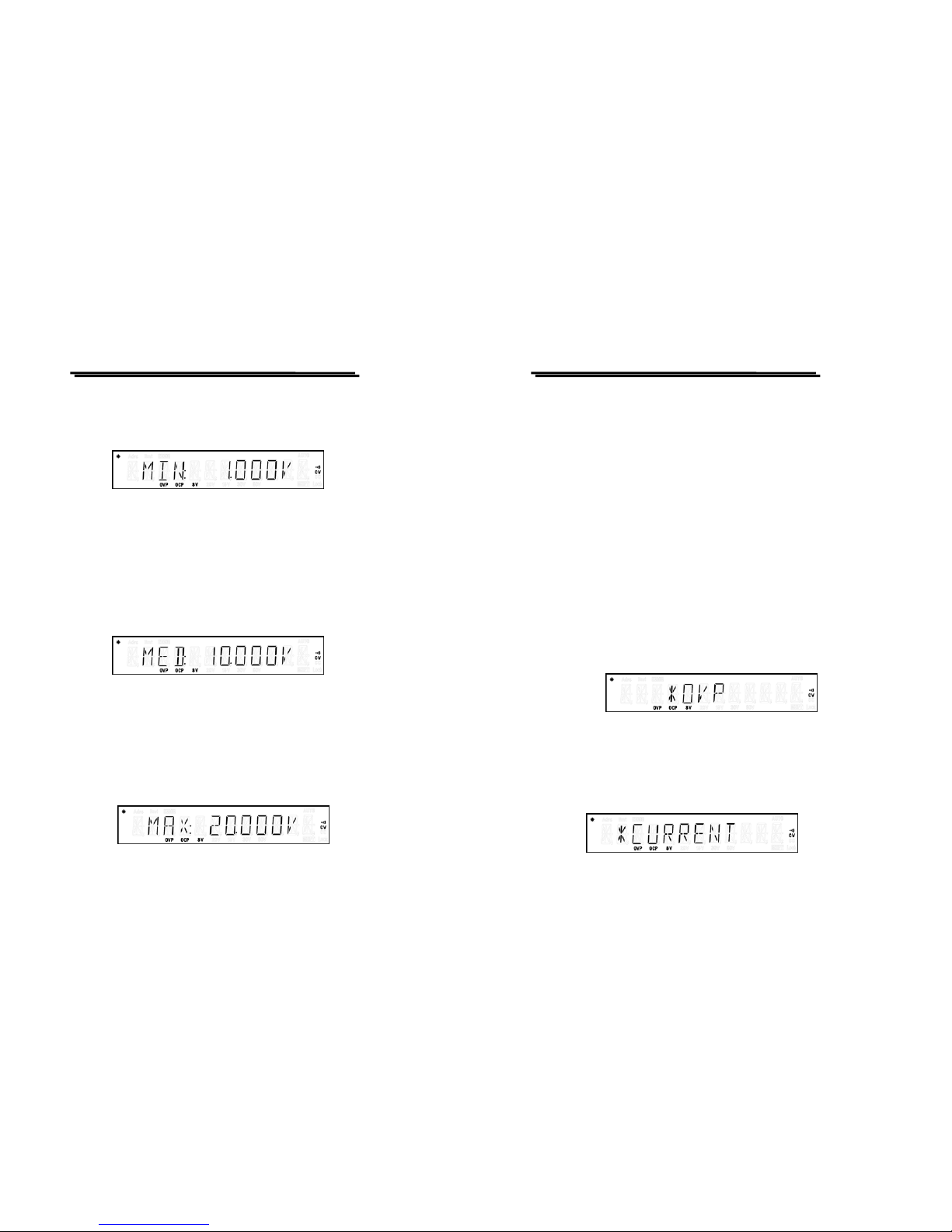
Set to [VOLTAGE] by using the knob and press [ENTER] getting into
voltage calibration procedure.
Page 29
PSM-SERIES PROGRAMMABLE POWER SUPPLY
USER MANUAL
⎯ ⎯
51
[Step 3.1]
Firstly, proceed the calibration procedure of LO calibrated point, input
DMM measurement value, then press [ENTER].
Note: The DMM selected for the measurement must have the resolution of
4 digits after the decimal point at least, and take three digits after the
decimal point to be the effective value and run off the rest.
[Step 3.2]
Next, proceed the calibration procedure of MI calibrated point, input
DMM measurement value, then press [ENTER].
Note: The DMM selected for the measure ment must have the reso lution o f
4 digits after the decimal point at least, and take three digits after the
decimal point to be the effective value and run off the rest.
[Step 3.3]
Finally, proceed the calibration procedure of HI calibrated point, input
DMM measurement value, then press [ENTER].
PSM-SERIES PROGRAMMABLE POWER SUPPLY
USER MANUAL
⎯ ⎯
52
Note: The DMM selected for the measure ment must have the reso lution o f
4 digits after the decimal point at least, and take three digits after the
decimal point to be the effective value and run off the rest.
Now, switch to SAVE by using the knob and press [ENTER] to leave the
mode with storing. Also can press [SHIFT][ .] to leave the mode without
storing.
【Step 4】
Set to [O.V.P.] by using the knob and press [ENTER] getting into Over
Voltage Protection auto-calibration procedure. Now, the output is in CV
mode (output terminal open).
Switch to SAVE by using the knob and press [ENTER] to leave the mode
with storing. Also can press [SHIFT][ .] to leave the mode without
storing.
[Step 5] Current Calibration Steps
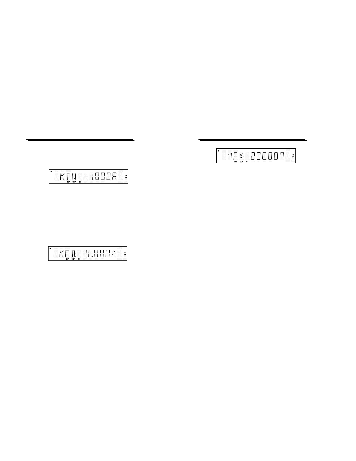
Set to [CURRENT] by using the knob and press [ENTER] getting into
Current calibration procedure.
Page 30
PSM-SERIES PROGRAMMABLE POWER SUPPLY
USER MANUAL
⎯ ⎯
53
[Step 5.1]
Firstly, proceed the calibration procedure of LO calibrated point, input
DMM measurement value, then press [ENTER].
Note: The current measurement method, please refer to 6-3. Measurement
technique. Now, the DMM selected for the measurement must have
the resolution of 3 digits after the decimal point at least.
[Step 5.2]
Next, proceed the calibration procedure of MI calibrated point, input
DMM measurement value, then press [ENTER].
[Step 5.3]
Finally, proceed the calibration procedure of HI calibrated point, input
DMM measurement value, then press [ENTER].
PSM-SERIES PROGRAMMABLE POWER SUPPLY
USER MANUAL
⎯ ⎯
54
Page 31
PSM-SERIES PROGRAMMABLE POWER SUPPLY
USER MANUAL
⎯ ⎯
55
Now, switch to SAVE by using the knob and press [ENTER] to leave the
mode with storing. Also can press [SHIFT][ .] to leave the mode without
storing.
Caution. When proceed the current ad
j
ustment, please
use a Shunt with sufficient Watt to overcome the
problem of temperature rising. A Shunt with
g
eneral
material of Man
g
anin can be used as long as its
temperature is less than 85℃.
[Step 6]
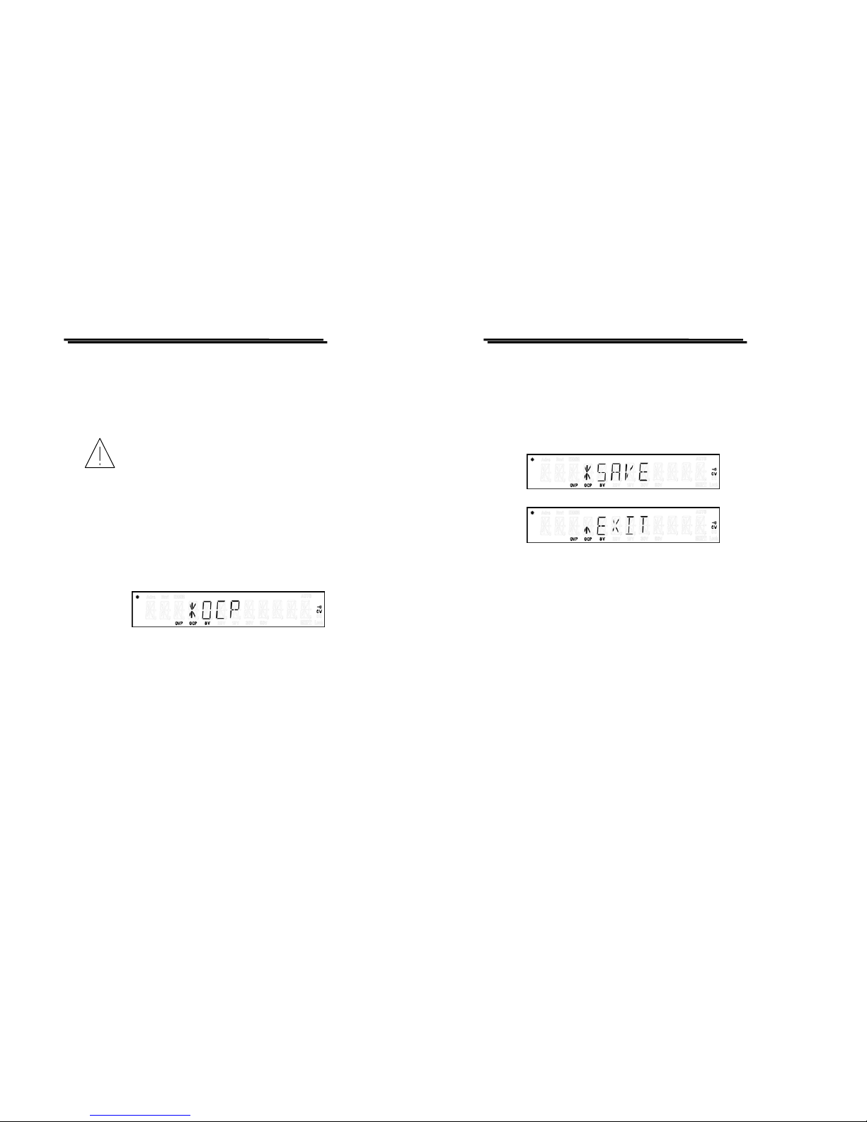
Set to [O.C.P.] by using the knob and press [ENTER] getting into Over
Current Protection auto-calibration procedure. Now, the output is in CC
mode (output terminal short).
Switch to SAVE by using the knob and press [ENTER] to leave the mode
with storing. Also can press [SHIFT][ .] to leave the mode without
storing.
PSM-SERIES PROGRAMMABLE POWER SUPPLY
USER MANUAL
⎯ ⎯
56
[Step 7]
Set to [SAVE] and press [ENTER] to complete the calibration proced ure
with storing. If want to cancel the calibration, using the knob to set the
cursor to [EXIT] and press [ENTER] to terminate the procedure without
storing.
6-5. Cleaning
To clean the power supply, use a soft cloth dampened in a solution of mild
detergent and water. Do not spray cleaner directly onto the instrument,
since it may leak into the cabinet and cause dama ge. Do not use chemic als
containing benzine, benzene, toluene, xylene, acetone, or similar solvents.
Do not use abrasive cleaners on any portion of the instrument.
Page 32
PSM-SERIES PROGRAMMABLE POWER SUPPLY
USER MANUAL
⎯ ⎯
57
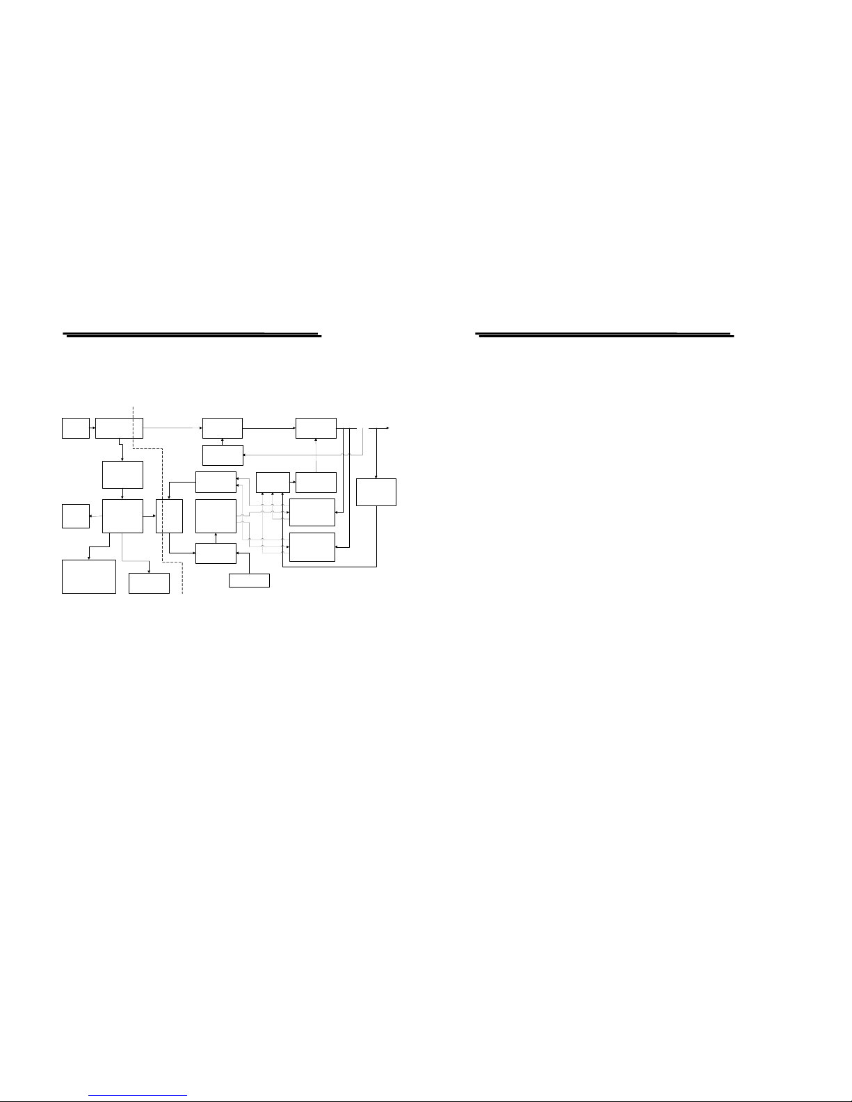
7. THE SYSTEM DIAGRAM AND DESCRIPTION
7-1. Block Diagram
The graph above is the system diagram of PSM-SERIES, which consists of
Micro Processor Unit (MPU), Digital to Analog Converter (DAC), Analog
Switch Circuit, Reference Voltage Circuit, Driver Circuit, Control Circuit,
Comparator, Phase Control and etc.
AC
INPUT
TRANSFORMER
PRE_
REGULATOR
VOLTAGE
COMPARATOR
CURRENT
COMPARATOR
D TO A
CONVERTER
REFERENCE
ANALOG
SWITCH
AND SAMPLE
HOLD
MICRO
CONTROL
VFD
DISPLAY
KEYBOARD
AUX
RECTIFIER
AND FILTER
SERIES
REGULATOR
AMPLIFIER
OR
GATE
O/P
INTERFACE
RS-232 OR GPIB
PHASE
CONTROL
PROTECTION
CIRCUIT
A TO D
CONVERTER
OPTO-
COUPLE
R
PSM-SERIES PROGRAMMABLE POWER SUPPLY
USER MANUAL
⎯ ⎯
58
7-2. The Configuration of Block System
The whole Block system consists of two Circuit Blocks, Digital Control
circuit (connected to the ground) and power output circuit (isolated from
the ground):
Digital Control circuit: MPU (Micro Processor Unit), VFD DISPLAY,
Interface Control Card, GPIB (IEEE-488) and RS-232.
Power output circuit: DAC (Digital to Analog Converter), ADC (Analog
to Digital Converter), Analog Switch Circuit, Reference
Voltage Circuit, Driver Circuit, Control Circuit,
Comparator and Phase Control.
The MPU is the heart of PSM-SERIE S control the DAC(digita l to analog
converter) control to provide the required reference voltage source of
voltage, current, Over Voltage protection, Over Current protection in order
to make the accurate setting and protection. Then, use the reference
voltage to control the Analog Switch Circuit to achieve high quality and
high accuracy output. Beside, the protection precaution detected by the
hardware can reach speedy and accurate purpose.
 Loading...