

Page 1

LCR-800 Series User Manual
CONTENTS PAGE
1. INTRODUCTION……………………………………..……... 1
LCR-800 Series User Manual
SAFETY TERMS AND SYMBOLS
These terms may appear in this manual or on the product:
2. PRECAUTIONS BEFORE OPERATION…….…………….
2-1.Unpacking the instrument………………….…………….
2-2.Checking the Line Voltage…………………..……………
2-3.Environment……………………………………..………..
2-4.Equipment Installation and Operation…………………
3. PANEL DESCRIPTION…...……………………..………….. 4
OPERATION…………….………………………………...….
4.
4-1.Connects to DUT….………………..………….……..…...
4-2.Start-Up……….....……………………………..………….
4-3.Zeroing…………………………………………………….
4-4.Menu Functions.…..………………………………………
4-5.Measurement Conditions…..……………………………..
SPECIFICATIONS…………………………………………...
5.
6. MESSAGE CODE.………………………………………….... 44
7. MAINTENANCE....…………………………………………...
7-1.Cleaning……………………………………………………
7-2.Battery Replacement……………………………………...
7-3.Recall Calibration………………………………………...
8. OPTION 1 (BIN Function for LCR-826/827/829 only)……..
8-1. BIN Functions for Components Sorting……………..….
8-2. BIN Setting Conditions.....……………………………….
8-3. BIN Range Setting: Component Sorting Range..............
11
18
35
45
45
45
46
48
48
50
56
2
2
2
3
3
8
8
8
8
The following symbols may appear in this manual or on the product:
WARNING: Warning statements identify condition or practices
that could result in injury or loss of life.
CAUTION: Caution statements identify conditions or practices
that could result in damage to this product or other property.
DANGER ATTENTION Protective Frame or Chassis
High Voltage refer to Manual Conductor Terminal
Terminal
9. OPTION 2……………………………………………………..
9-1.On-line procedure…………………………………………
9-2.RS232 VIEWER Software Operation…………………...
9-3.The Configuration of Cable………………………………
i
65
65
69
74
ii
Page 2

LCR-800 Series User Manual
FOR UNITED KINGDOM ONLY
NOTE: This lead / appliance must only be wired by competent persons
WARNING: THIS APPLIANCE MUST BE EARTHED
IMPORTANT: The wires in this lead are coloured in accordance with the
following code:
Green/ Yellow: Earth
Blue: Neutral
Brown: Live (Phase)
LCR-800 Series User Manual
This cable/appliance should be protected by a suitably rated and approved
HBC mains fuse: refer to the rating information on the equipment and/or
user instructions for details. As a guide, cable of 0.75mm
2
should be
protected by a 3A or 5A fuse. Larger conductors would normally require
13A types, depending on the connection method used.
Any moulded mains connector that requires removal /replacement must be
destroyed by removal of any fuse & fuse carrier and disposed of
immediately, as a plug with bared wires is hazardous if a engaged in live
socket. Any re-wiring must be carried out in accordance with the
information detailed on this label.
As the colours of the wires in main leads may not correspond with the
colours marking identified in your plug/appliance, proceed as follows:
The wire which is coloured Green & Yellow must be connected to the Earth
terminal marked with the letter E or by the earth symbol
or coloured
Green or Green & Yellow.
The wire which is coloured Blue must be connected to the terminal which is
marked with the letter N or coloured Blue or Black.
The wire which is coloured Brown must be connected to the terminal
marked with the letter L or P or coloured Brown or Red.
If in doubt, consult the instructions provided with the equipment or contact
the supplier.
iii
iv
Page 3

LCR-800 Series User Manual
LCR-800 Series User Manual
EC Declaration of Conformity
We
GOOD WILL INSTRUMENT CO., LTD.
No. 7-1, Jhongsing Rd., Tucheng City, Taipei County 236, Taiwan
GOOD WILL INSTRUMENT (SUZHOU) CO., LTD.
No. 69 Lushan Road, Suzhou New District Jiangsu, China.
declare that the below mentioned products:
LCR-817/819/827/829/816/826/821
are herewith confirmed to comply with the requirements set out in the Council
Directive on the Approximation of the Law of Member States relating to
Electromagnetic Compatibility (89/336/EEC, 92/31/EEC, 93/68/EEC) and Low
Voltage Equipment Directive (73/23/EEC, 93/68/EEC).
For the evaluation regarding the Electromagnetic Compatibility and Low Voltage
Equipment Directive, the following standards were applied:
EN 61326-1: Electrical equipment for measurement, control and laboratory use ––
EMC requirements (1997+A1: 1998)
Conducted and Radiated Emissions
EN 55011 : 1998 Group I Class A
Current Harmonic
EN 61000-3-2: 2000
Voltage Fluctuation
EN 61000-3-3: 1995
————————————————
————————————————
————————————————
Electrostatic Discharge
IEC 61000-4-2: 1995
Radiated Immunity
IEC 61000-4-3: 1995
Electrical Fast Transients
IEC 61000-4-4: 1995
Surge Immunity
IEC 61000-4-5: 1995
Conducted Susceptibility
IEC 61000-4-6: 1996
Voltage Dips/ Interrupts
IEC 61000-4-11: 1994
1. INTRODUCTION
The precise LCR meter series are automatic, user programmable instruments
that provide high reliability and great precision for measuring a wide variety of
impedance parameters. The frequency range of LCR-819/829 covers from 12Hz
to 100kHz, LCR-817/827 from 12Hz to 10kHz, LCR-816/826 from 100Hz to
2kHz, and LCR-821 from 12Hz to 200kHz. The basic accuracy is 0.1% for LCR-
827/829/816/826, 0.05% for LCR-817/819/821. The measured results can be
displayed on the high quality LCD monitor with decimal points and units. The
measured result resolution is five full digits for Inductance (L), Capacitance (C),
Resistance (R) and absolute value of impedance (|Z|) [four full digits for
Dissipation factor (D), Quality factor (Q), R with C, R with L, 2 digits after
decimal dot for phase angle (θ)]. In the meantime, the LCD monitor is also shown
the control status and parameters of settings. The keypads are easy for menu
programming. The LCR Meters’ test fixture (option) is a method of convenient,
reliable, guarded 4-terminal/2 wires connection of radial and axial leaded
components to the LCR Meters. Test conditions can be stored and recalled from
internal memory that will reduce the setup time for measurement preparing.
Low Voltage Equipment Directive 73/23/EEC & amended by 93/68/EEC
Safety Requirements
IEC/EN 61010-1:2001
v
1
Page 4

LCR-800 Series User Manual
2. PRECAUTIONS BEFORE OPERATION
2-1. Unpacking the instrument
The product has been fully inspected and tested before shipping from the
factory. Upon receiving the instrument, please unpack and inspect it to
check if there are any damages caused during transportation. If any damage
is found, notify the bearer and/or the dealer immediately.
LCR-800 Series User Manual
2-3. Environment
The normal ambient temperature range of the LCR Meters is from 10° to
50°C. To operate the instrument over this specific temperature range may
cause damage to the circuits.
Do not use the LCR Meters in a place where strong magnetic or electric
field exists as it may disturb the measurement.
2-4. Equipment Installation and Operation
2-2. Checking the Line Voltage
The LCR Meters can be operated with AC power source between 100V
rated voltage and 240V rated voltage at a frequency of 50 to 60Hz, no AC
voltage selector is necessary. Power connection to rear panel is through an
AC inlet module comprised of an AC connector and fuse holder. To change
the fuse proceed as follows:
z Remove the fuse holder by inserting a small flat head screwdriver
behind the small tab to force the holder outward.
z Install the correct fuse (slow-blow, 3A, 250Vac).
z Re-install the fuse holder back into the LCR Meters AC inlet module,
push in and lock.
WARNING: To avoid electrical shock the power cord protective
grounding conductor must be connected to ground.
WARNING: To avoid personal injury, disconnect the power cord
before removing the fuse holder.
Ensure there is proper ventilation for the vents in the LCR meters case. If
this equipment is used not according to the specification, the protection
provided by the equipment may be impaired.
WARNING: This is a Class A product. In a domestic environment
this product may cause radio interference in which case the user
may be required to take adequate measures.
2
3
Page 5

LCR-800 Series User Manual
LCR-800 Series User Manual
3. PANEL DESCRIPTION
(1). Power Switch
Turns AC Power on or off.
(2). Function key 一
Soft key functions as indicated on the adjacent LCD monitor.
(3). Function key 一
Soft key functions as indicated on the adjacent LCD monitor.
(4). Function key 一
Soft key functions as indicated on the adjacent LCD monitor.
(5). Function key 一
Soft key functions as indicated on the adjacent LCD monitor.
(6). MENU key
Enters menu display mode or exits sub menu back to main menu.
(7). Compound key
z For making numerical entries as labeled.
z Turns the “RANGE HOLD” mode on or off.
(8). Compound key
z For making numerical entries as labeled.
z Turns the “CONSTANT VOLTAGE” mode on or off.
(9). Compound key
z For making numerical entries as labeled.
z Measures the unit of Dissipation and Quality Factor in PPM.
(Note: The models of LCR-816 and 826 do not have this function.)
F1
F2
F3
F4
(10). Compound key
z For making numerical entries as labeled.
z Selects the “INTERNAL BIAS” mode or “EXTERNAL BIAS” mode. (If
this key function is switched to “INTERNAL BIAS” mode, the bottom
of LCD monitor will display the “INT.B” message. If the external DC
bias is selected, the bottom of LCD monitor will display the “EXT.B”
message.)
(11). Compound key
z For making numerical entries as labeled.
z Turns the INTERNAL BIAS mode or EXTERNAL BIAS mode “ON” or
“OFF”.
(12). Compound key
z For making numerical entries as “-“ (the negative sign).
z Inputs the “TEST FREQUENCY”.
(13). START (Compound key)
z Starts measurement sequence. Normally used in the “MANU” (Triggered)
mode.
z Selects “AUTO” or “MANU” mode by pressing this key for 3 seconds at
least.
z The LCR Meters will process the measurement automatically, if the
“AUTO” mode is selected.
↵ key (ENTER)
(14).
This key enables programming of all special functions, test frequency, test
voltage, averaging, delay, and nominal value etc.
(15). ‧ Symbol key
Inputs the decimal point
4
5
Page 6

LCR-800 Series User Manual
LCR-800 Series User Manual
(16). Numeral key—“2”
(17). Numeral key—“3”
(18). Numeral key—“5”
(19). Numeral key—“6”
(20). Numeral key—“9”
(21). Primary Display
This line can display the measured Inductance, Capacitance, or Resistance
(LCR-821 has Ζ).
(22). Secondary Display
This line can display the measured Quality Factor or Dissipation or ESR or
EPR (LCR-821 has Θ).
(23). Instrument status or indicates measurement results based on entered test
limits.
(24). Test conditions
(25). Input terminals
BNC connectors, connects to device under test (DUT).
FRONT PANEL
Connectors of the LCR Meters
Lforce (current, low)
Lsense (potential low)
Hsense (potential high)
Hforce (current, high)
BIAS
+
+
-
-
6
7
Page 7

LCR-800 Series User Manual
LCR-800 Series User Manual
4. OPERATION
4-1. Connects to DUT
The LCR Meters utilize the structure of four wires measurement which allows
accurate, easy, and stable measurements and avoids mutual inductance and
interference from measurement signals, noise and other factors inherent with
other types of connections. For the accuracy of measurement, GOODWILL
produces the cable set and test fixture (option) for connection directly to the
front panel BNC connectors.
4-2. Start-Up
Connects the power cord of the LCR Meters to the mains socket-outlet. Presses
POWER button of front panel to apply the AC power to the LCR Meters.
the
4-3. Zeroing
In order to eliminate strayed capacitance and impedance of test cable during the
measurement, the LCR Meters should be zeroed to correct for test cable and/or
test fixture errors before taking measurements. The corrections are calculated
and stored in memory of the LCR Meters during the zeroing process. Open and
short circuit zeroing should be done for test cable and/or test fixture. For the best
accuracy, the test cable and/or test fixture should be zeroed once per day at least
and each time test cable or test fixture is changed in general.
The zeroing process of open and short circuits are following:
Open Circuit
z The test cable or test fixture should be open with no component connected.
z Press MENU key.
z Press F1 key to select “OFFSET” menu.
z Press F1 key to select open circuit zeroing (the “CAP OFFSET” is indicated
on the adjacent LCD monitor.).
z After the BAR at the bottom of LCD monitor is filled to the full, the zeroing
process is done.
z If the zeroing process is successful, a message of “OK” will appear on the
LCD monitor. If failed, a message of “FAIL” will appear on the LCD
monitor.
Short Circuit
z The test cable should be connected or test fixture shorted (using a clean
copper wire, as short as possible).
z Press MENU key.
z Press F1 key to select “OFFSET” menu.
z Press F2 key to select short circuit zeroing (the “R/L OFFSET” is indicated
on the adjacent LCD monitor.).
z After the BAR at the bottom of LCD monitor is filled fully, the zeroing
process is done.
z If the zeroing process is successful, a message of “OK” will appear on the
LCD monitor. If failed, a message of “FAIL” will appear on the LCD
monitor.
Test Condition:
Test voltage=According to the actual test voltage.
Test speed = According to the actual test speed.
R.H = OFF
C.V = According to the actual test status.
For the summary, the zeroing menu can be chosen through menu selection as
shown in Figure 4-1 above.
NOTE: The “Open Circuit” and “Short Circuit” have to pass the test,
otherwise, the accuracy of the LCR Meters will become worse.
8
9
Page 8

LCR-800 Series User Manual
LCR-800 Series User Manual
L 1.2345H
Q 0.6789
TESTING
F : 1.000 kHz
V : 1.000 V
AUTO MANU INT.B OFF
CAP. R/L OFFSET
SET SORT
SET PARAMETER
CALIBRATION
R.H OFF
C.V OFF
SPEED
SLOW
DISPLAY
VALUE
MODE
L/Q
CIRCUIT
SERIES
MENU
OFFSET
SORT
SETTING
CALBRAT
EXIT
Press menu
key
Press F1 key
to the zeroing
menu
4-4. Menu Functions
All the LCR Meters’ programmable functions are controlled by the easy to use
menu displays. User can enter the menu mode by selecting the
MENU key that
calls up four top level menus, OFFSET, SORT, SETTING and CALBRAT.
Each one of these is comprised of a sub menu list whose functions are described
in detail below. User can enter one of four functions by pressing the
corresponding function key (just adjacent LCD monitor, see figure 4-2).
Press F1 key
to the zeroing
CAP. R/L OFFSET
SET SORT
SET PARAMETER
CALIBRATION
OFFSET
SORT
SETTING
CALBRAT
EXIT
menu
Press F2 key
to the bin sort
menu
Press F3 key
to the utility
menu
Press F4 key
to the
calibration
menu
OPEN TEST
SHORT TEST
Figure 4-1: Summary of zeroing menu
CAP
OFFSET
R/L
OFFSET
EXIT
10
Press F1 KEY for
open test
Press F2 KEY for
short test
Press MENU key
to exit menu screen
Figure 4-2: four main menu screen
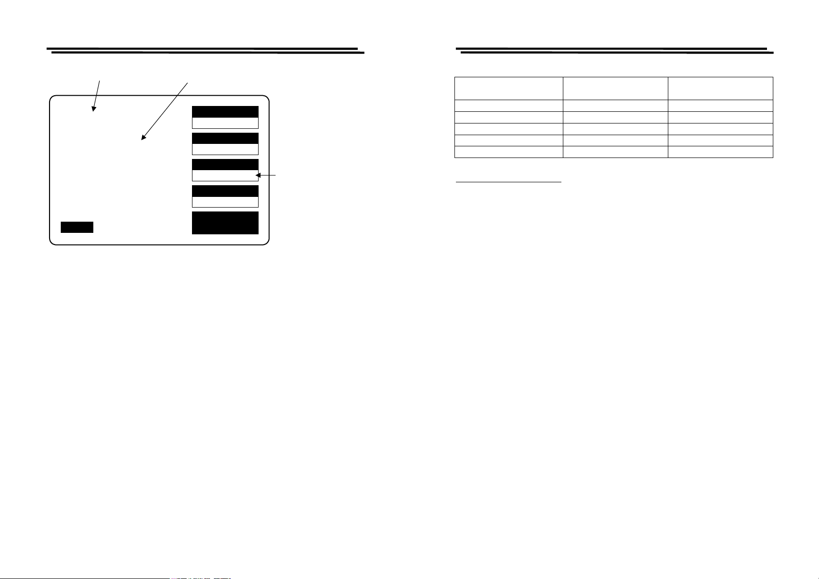
4-4-1. Primary & Secondary Display
For the LCR Meters, four combinations of two parameters can be measured and
displayed simultaneously. One referred to the “Primary Display” (displayed
first) and the other to the “Secondary Display”. Depending on the component
type the primary and secondary display could be L & Q, C & D, C & R or R and
Q, and add L & R and Z & θ to LCR-821. The parameter can be chosen by
pressing
F3 key as shown in Figure 4-3.
11
Page 9
LCR-800 Series User Manual
LCR-800 Series User Manual
Primary
Display
L 1.2345H
Q 0.6789
F : 1.000 kHz
V : 1.000 V
AUTO MANU INT.B OFF
Figure 4-3. Primary & Secondary display
User can select R/Q for resistor measurement; select L/Q or L/R for inductor
measurement; select Z/θ for impedance measurement, select either C/D or C/R
for capacitor measurement.
Note: Only LCR-821 can select Z/θ and L/R measurement modes.
4-4-2. Series & Parallel Equivalent Circuit
Impedance that is neither a pure resistance nor a pure reactance can be
represented at any specific frequency by either a series or a parallel combination
of resistance and reactance. Such representation is called “equivalent circuit”.
The component value of the “Primary Display” depends on which equivalent
circuit (series or parallel) is chosen. In normal, the component manufacturer
shall specify how a component is to be measured (usually series) and at what
frequency. Please refer to Figure 4-4.
Secondary
Display
TESTING
R.H OFF
C.V OFF
SPEED
SLOW
DISPLAY
VALUE
MODE
L/Q
CIRCUIT
SERIES
MENU
Press F3 key
successively in
order to select the
different
measurement mode
(R/Q, C/D, C/R,
L/Q, Z/θ, L/R)
z Measurement Function
Measurement Mode Series Equivalent Circuit Parallel Equivalent
Circuit
R / Q
C / D
C / R
Z / θ (degree)
L / R
Suggested Test Conditions:
Inductors less than 10µH: Series, 100kHz.
Inductors from 10 µH to 1mH: Series, 10kHz.
Inductors from 1mH to 1H: Series, 1kHz.
Inductors greater than 1H: Series, 0.1kHz.
Capacitors less than 10pF: Parallel, 100kHz.
Capacitors from 10 to 400pF: Series or Parallel, 10kHz.
Capacitors from 400 to 1µF: Series, 1kHz.
Capacitors greater than 1µF: Series, 0.1 or 0.12kHz.
Resistor less than 1kΩ: Series, 1kHz.
Resistor from 1kΩ to 10MΩ: Parallel, 0.25kHz.
Resistor greater than 10 MΩ: Parallel, 0.03kHz
Unless for special reason, always select “Series” for capacitors and inductors.
This has traditionally been standard practice. For very small capacitance or
inductance, select a higher test frequency for better accuracy. For very large
capacitance or inductance, select a lower test frequency for better accuracy. For
dc resistance, select a lower test frequency to minimize ac effects.
Because the reactive component most likely to be represented in a low resistance
resistor is series inductance, the “Series” is selected for a resistor below about
1kΩ. If a resistor large than 10MΩ, select “Parallel” that because the reactive
component most likely to be represent in a high resistance resistor is shunt
capacitance. If the Q is less than 0.1, the measured Rp is probably very close to
the dc resistance.
99
99
99
9
99
12
13
Page 10

LCR-800 Series User Manual
LCR-800 Series User Manual
The total loss of a capacitor can be expressed in several ways, including D and
“ESR” (Equivalent Series Resistance). “ESR” is typically much larger than
actual “ohmic” series resistance of the wire leads and foils that are in series with
the heart of a capacitor physically, because ESR includes also the effect of
dielectric loss. ESR is related to D by the formula: ESR = Rs = D/ωCs. Where ω
represents “omega” = 2 pi time frequency.
Although it is traditional to measure series inductance of inductors, there are
situations in which the parallel equivalent circuit better represents the physical
component. For small “air-core” inductors, the significant loss mechanism is
usually “ohmic” or “copper loss” in the wire, therefore the series circuit is
appropriate. Nevertheless, for an “iron core”, the significant loss mechanism can
be “core loss”, therefore, the parallel equivalent circuit is appropriate which
being a better model of the inductor.
SPEED
L 1.2345H
Q 0.6789
TESTING
F : 1.000 kHz
V : 1.000 V
AUTO MANU INT.B OFF
Figure 4-4. Selections of Series & Parallel Circuit
R.H OFF
C.V OFF
SLOW
DISPLAY
VALUE
MODE
L/Q
CIRCUIT
SERIES
MENU
Press F4 key to
select the Series
or Parallel circuit
4-4-3. Measurement Displays
The measured results of the LCR Meters can be shown on the LCD monitor in
three ways: VALUE
appropriate item for measurement. Please refer to Figure 4-5.
VALUE
The LCD monitor will display the measured value of both the primary and
secondary parameter, shown with decimal and units. The resolution of primary
display (L, C, R or Z) is five digits. The resolution of secondary display (D, Q, R
with C or R with L) is four digits. The resolution of secondary display (θ) is at 2
digits after decimal point. The message “TESTING” is displayed when a test is
in process.
DELTA%
The “DELTA%” shows the percent deviation of the measured L, C, R or Z value
from a stored NOMINAL VALUE. The sign of deviation is indicated.
DELTA
The LCR difference is similar to the DELTA% except that the deviation is shown
in suitable units (ohms, henries, etc).
L 1.2345H
Q 0.6789
F : 1.000 kHz
V : 1.000 V
AUTO MANU INT.B OFF
, DELTA%, or DELTA. User can press F2 key to select the
SPEED
SLOW
TESTING
R.H OFF
C.V OFF
DISPLAY
VALUE
MODE
L/Q
CIRCUIT
SERIES
MENU
Press F2 key to select the
three different measuring
display ("VALUE",
"DELTA%", or "DELTA").
14
Figure 4-5. Types of measurement display
15
Page 11
LCR-800 Series User Manual
4-4-4. Nominal Value
LCR-800 Series User Manual
Allows entry of a “Nominal Value” for the primary parameter which is the basis
for the measurement result in “DELTA” or “DELTA %”. Accepts numerical entry
up to five digits with decimal. Units are depended on which measurement
displays selected.
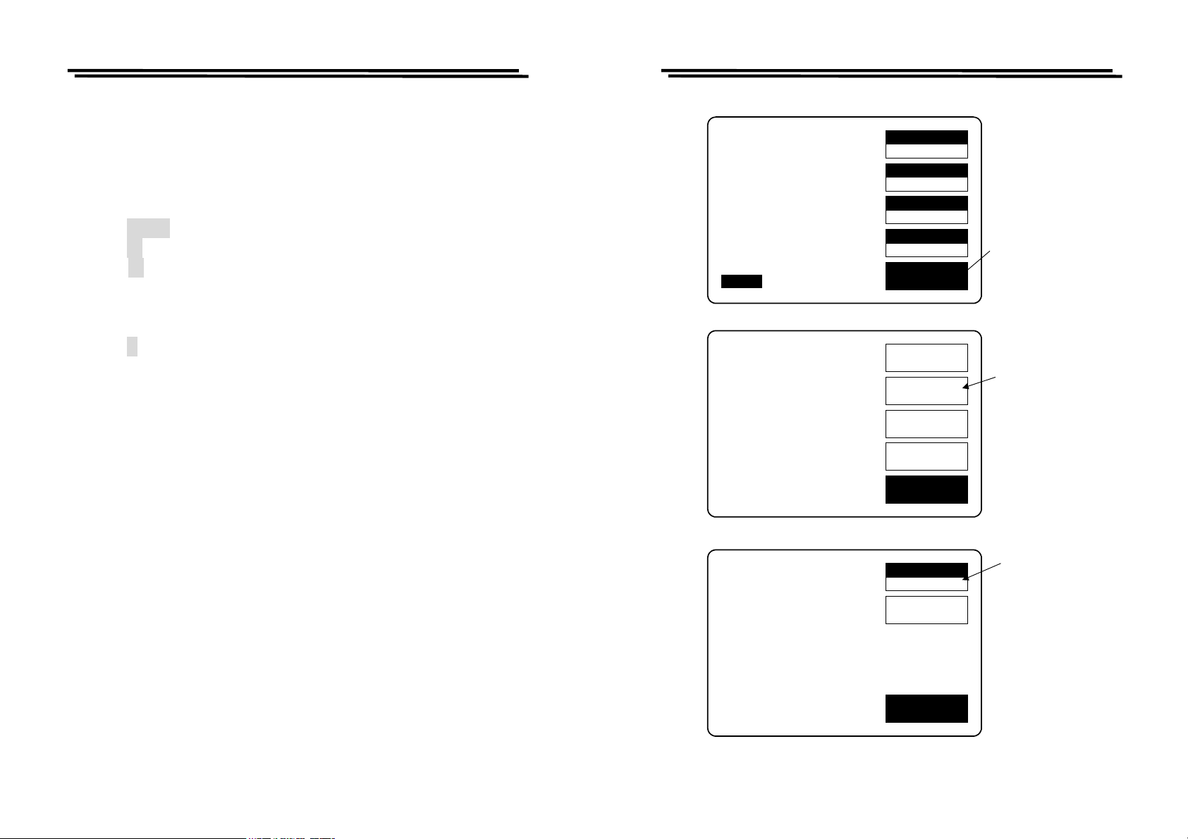
Steps of “Nominal Value” input (Figure 4-6):
z Press MENU key.
z Press F2 key to select “SORT” menu.
z Press F1 key to select “Nominal Value” (the “NOM.VAL” is indicated on
the adjacent LCD monitor).
z Input the nominal value via the numeral keys (5 digits with decimal
maximum).
z Press ↵ key
z After the BAR at the bottom of LCD monitor is filled fully, the “Nominal
Value” input is done.
4-4-5. Selection of Measurement Speed
One of three measurement speeds SLOW, MEDIUM, or FA ST could be
selected (Figure 4-7). The continuous mode speeds are about 1, 5, and 12
measurement per second respectively. The trade-off is accuracy vs. speed. LCR-
817/819 will take a more accurate measurement at a slower rate. The trade-off is
as follows
L 1.2345H
Q 0.6789
TESTING
F : 1.000 kHz
V : 1.000 V
AUTO MANU INT.B OFF
CAP. R/L OFFSET
SET SORT
SET PARAMETER
CALIBRATION
R.H OFF
C.V OFF
SPEED
SLOW
DISPLAY
VALUE
MODE
L/Q
CIRCUIT
SERIES
MENU
OFFSET
SORT
SETTING
CALBRAT
EXIT
Press menu
key
Press F2 key
to the sort
menu
SLOW speed : More than 1 measurement per second, at 0.05% accuracy
(or better)
MEDIUM speed : More than 3 measurements per second, at 0.1% accuracy
(or better)
FAST speed : More than 7 measurements per second, at 0.24% accuracy
(or better)
* For the details of accuracy, please refer to the specifications.
* Regarding the models LCR-826/827/829, please refer to 4-5-10 Handler
Interface Timing.
16
NOM.VAL = 77.000pF
OPTION 1
NOM.VAL
24.870
HANDLER
EXIT
Figure 4-6. Steps of “Nominal Value” input.
17
Press F1 key to
input the
nominal value
Page 12

LCR-800 Series User Manual
Press F1 key to select the three different measurement
speed. (SLOW, MEDIUM, or FAST)
SPEED
L 1.2345H
Q 0.6789
TESTING
F : 1.000 kHz
V : 1.000 V
AUTO MANU INT.B OFF
Figure 4-7. Selection of measurement speed
4-5. Measurement Conditions
4-5-1. Bias Voltage
There are two available bias voltage modes: “Internal” and “External”.
R.H OFF
C.V OFF
SLOW
DISPLAY
VALUE
MODE
L/Q
CIRCUIT
SERIES
MENU
LCR-800 Series User Manual
Press the numerical 7 key
to select either internal or
external bias voltage
7
BIAS
4
PPM
1
C.V
0
R.H
8
ON/OFF
5 6
2 3
.
Press the numerical 8 key to
turn either internal or external
bias voltage on or off.
9
S
T
A
R
T
_
FREQ
Internal:
An internal DC 2 volts bias voltage will apply to the device under test.
External:
An external DC bias voltage between 0 and 30 volts can be applied to the device
under test. The external bias connection is located on the rear panel. The
maximum current is 200mA. The supply of bias voltage has to be floating, don’t
connect either side to ground. It’s better to wait approximately 1 second for
taking a reading after initiating a testing process, therefore, the device under test
will stabilize after bias voltage applied. The DC bias voltage should be applied
only to capacitors in general. If the DC bias voltage is applied to device of low
impedance, the unreliable testing results will occur. When the external bias is
applied, please join the function of C.V.ON (Constant voltage On) in use.
18
L 1.2345H
Q 0.6789
TESTING
F : 1.000 kHz
V : 1.000 V
AUTO MANU INT.B OFF
Indication of internal or
external bias voltage
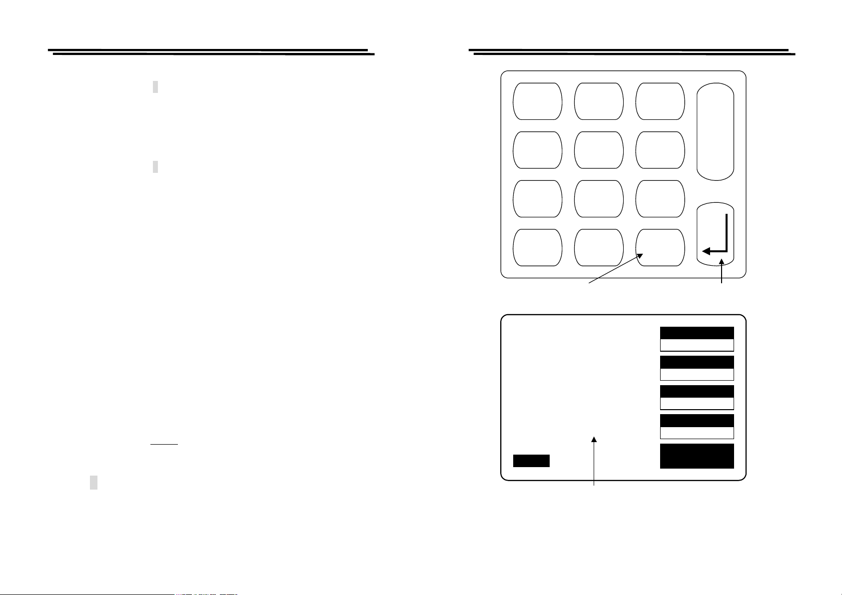
Figure 4-8. Selection of “BIAS” voltage
R.H OFF
C.V OFF
19
SPEED
SLOW
DISPLAY
VALUE
MODE
L/Q
CIRCUIT
SERIES
MENU
Page 13
LCR-800 Series User Manual
Steps of “BIAS” voltage selection (Figure 4-8):
z Press compound key 7 to selects the “INTERNAL BIAS” or “EXTERNAL
BIAS” on the main menu. (If this key function is switched to “INTERNAL
BIAS”, the bottom of LCD monitor will display the “INT.B” message. If the
external DC bias is selected, the bottom of LCD monitor will display the
“EXT.B” message.
z Press compound key 8 to turn either “INTERNAL BIAS” or “EXTERNAL
BIAS” mode “ON” or “OFF” on the main menu.
4-5-2. Test Frequency
The numerical input of test frequency accepts up to 5 digits with decimal. User
can input any desired frequencies, however, the actual frequency executed for the
LCR Meters is always the closest one of the 504 available frequencies. The 504
frequencies can be calculated by the following formulas:
3kHz/n, where n range is from 13 to 250 (freq. 0.012 to 0.23077kHz)
60kHz/n, where n range is from 4 to 256 (freq. 0.23438 to 15kHz)
200kHz/n, where n range is from 1 to 13 (freq. 15.385 to 200kHz)
The “nominal value” of an available frequency can be calculated from the proper
one of the three formulas.
The range of test frequency between 12Hz and 10kHz is for LCR-817/827,
between 12Hz and 100kHz for LCR-819/829, between 100Hz and 2kHz for
LCR-816/826, and between 12Hz and 200kHz for LCR-821. To select the test
frequency, just key in the desired frequency via these numerical keys, the LCR
Meters will take the nearest available test frequency from the 504 available test
frequencies automatically.
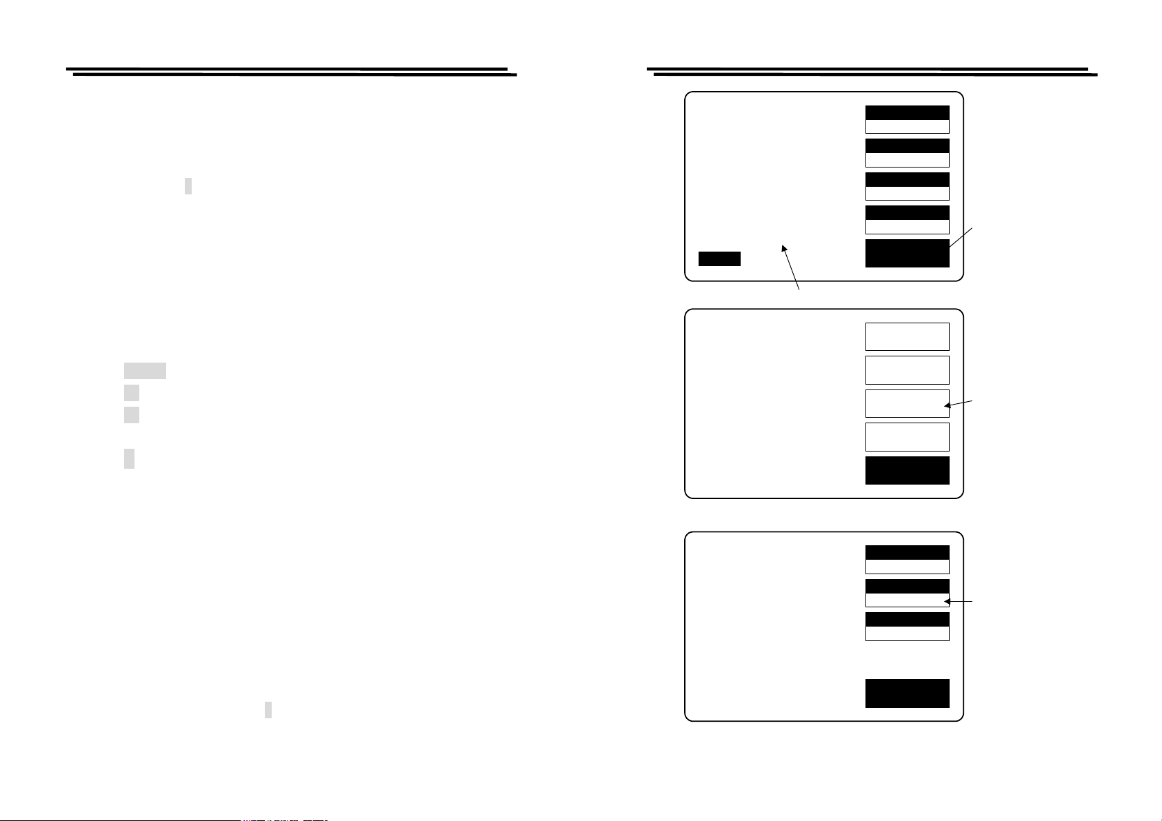
Steps of “Test Frequency” selection (Figure 4-9):
z Press compound key FREQ .
z Input the desired frequency in kilohertz.
z Press ↵ key.
Note: After test frequency has been changed, the zeroing of “Open/Short
circuit” must be done again for the best accuracy.
LCR-800 Series User Manual
7
BIAS
4
PPM
1
C.V
0
R.H
Press - key to input test
frequency
L 1.2345H
Q 0.6789
F : 1.000 kHz
V : 1.000 V
AUTO MANU INT.B OFF
test frequency
Figure 4-9. Inputs of test frequency
8
ON/OFF
5 6
2 3
.
TESTING
R.H OFF
C.V OFF
9
S
T
A
R
T
_
FREQ
Press enter key to confirm the
inputs.
SPEED
SLOW
DISPLAY
VALUE
MODE
L/Q
CIRCUIT
SERIES
MENU
20
21
Page 14
LCR-800 Series User Manual
LCR-800 Series User Manual
4-5-3. D/Q in PPM (parts per million)(Invalid for LCR-816/826)
If the value of D or Q is less than 0.0100, user can select DQ in PPM to improve
the resolution by a factor of 100. The units of D and Q in PPM are dimensionless
and expressed as a decimal ratio with the multiplier of 1000000. User can just
press compound key
4 to select the unit of D or Q in PPM. To disable the DQ in
PPM feature, press the same key again.
4-5-4. Test Voltage
The range of test voltage is from 5mV to 1.275V in increments of 5mV. The
actual voltage through the DUT is never more than the source voltage. The DUT
impedance and the source resistance of the LCR Meters decide the actual test
voltage. The smallest voltage through the DUT will be 20% smaller of the source
voltage in general. The programming of test voltage is as follows (Figure 4-10):
z Press MENU key.
z Press F3 key to select “SETTING” menu.
z Press F2 key to select “VOLT” menu.
z Input the desired value via the numeral keys.
z Press ↵ key
z After the BAR at the bottom of LCD monitor is filled fully, the “Test
Voltage” input is done.
Note: When the test frequency is at 200kHz, the test voltage must be more than
100mV.
4-5-5. Constant Voltage Source
If the DUT have to be measured at a particular test voltage, the LCR Meters
provides the constant voltage feature. After “Constant Voltage” is selected, The
LCR Meters will keep a source resistance of 25Ω. Therefore, the test voltage is
constant for any DUT impedance which large than 25Ω. If “Constant Voltage” is
selected, the measurement accuracy will cause a reduction by a factor of three.
User can just press compound key
1 to select the feature of “Constant Voltage”.
To disable this feature, press the same key again.
L 1.2345H
Q 0.6789
TESTING
F : 1.000 kHz
V : 1.000 V
AUTO MANU
CAP. R/L OFFSET
SET SORT
SET PARAMETER
CALIBRATION
MOMORY NO: 1
VOLTAGE = 1.000 V
AVERAGE = 1
Figure 4-10. Programming of test voltage.
R.H OFF
C.V OFF
INT.B OFF
Test Voltage
SPEED
SLOW
DISPLAY
VALUE
MODE
L/Q
CIRCUIT
SERIES
MENU
OFFSET
SORT
SETTING
CALBRAT
EXIT
MOMORY
1
VOLT
1.000
AVGE
1
EXIT
Press menu
key
Press F3 key
to the setting
menu
Press F2 key to
input the desired
test voltage
22
23
Page 15
LCR-800 Series User Manual
4-5-6. Range Hold
If a DUT is removed from the test cable or fixture during the “Continuous” mode,
the feature of “Range Hold” can avoid range switching. Due to the test time can
be reduced, “Range Hold” is a useful utility for repetitive devices measurement.
User can just press compound key
0 to select the feature of “Range Hold”. To
disable this feature, press the same key again.
4-5-7. Averaging
If this function is enable, the testing time will multiple by the number of tests
(from 1 to 255). Hence, the accuracy can be enhanced. The measurement time
will be increased to the contrary. The programming of “Averaging” is as follows
(Figure 4-11):
z Press MENU key.
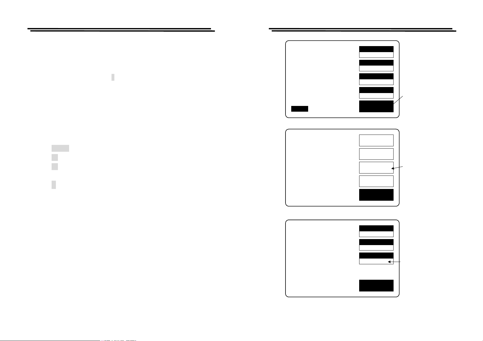
z Press F3 key to select “SETTING” menu.
z Press F3 key to select “AVGE” menu.
z Input the desired value via the numeral keys.
z Press ↵ key
z After the BAR at the bottom of LCD monitor is filled to the full, the
“Averaging” input is done.
LCR-800 Series User Manual
L 1.2345H
Q 0.6789
F : 1.000 kHz
V : 1.000 V
AUTO MANU
CAP. R/L OFFSET
SET SORT
SET PARAMETER
CALIBRATION
INT.B OFF
TESTING
R.H OFF
C.V OFF
SPEED
SLOW
DISPLAY
VALUE
MODE
L/Q
CIRCUIT
SERIES
MENU
OFFSET
SORT
SETTING
CALBRAT
EXIT
Press menu
key
Press F3 key
to the setting
menu
24
MOMORY NO: 1
VOLTAGE = 1.000 V
AVERAGE = 1
Figure 4-11. Programming of averaging.
25
MOMORY
1
VOLT
1.000
AVGE
1
EXIT
Press F3 key to
input the desired
averaging amount
Page 16
LCR-800 Series User Manual
4-5-8. Memory
The LCR Meters have two memory functions: Recall and Store. The current
measurement conditions can be saved into the memory unit or recalled a
previously saved measurement conditions set from the LCR Meters memory.
There are 100 memory blocks totally. The programming of “Memory Store /
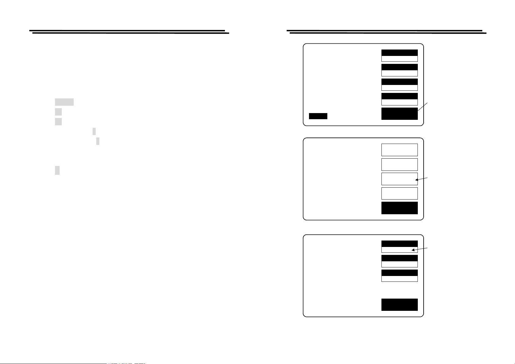
Recall” can be used as described below (Figure 4-12):
z Press MENU key.
z Press F3 key to select “SETTING” menu.
z Press F1 key to select “MEMORY” menu.
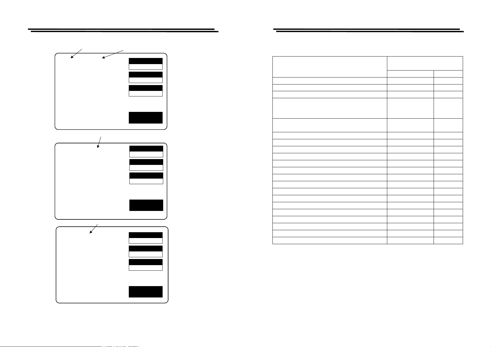
z Press compound key 1 to recall a previously saved memory block. or
z Press compound key 2 to store the current measurement conditions into
memory.
z Input the number of desired memory block. (1~100)
z Press ↵ key
z After the BAR at the bottom of LCD monitor is filled to the full, the process
of “Memory Store/Recall” is done.
LCR-800 Series User Manual
L 1.2345H
Q 0.6789
F : 1.000 kHz
V : 1.000 V
AUTO MANU
CAP. R/L OFFSET
SET SORT
SET PARAMETER
CALIBRATION
INT.B OFF
TESTING
R.H OFF
C.V OFF
SPEED
SLOW
DISPLAY
VALUE
MODE
L/Q
CIRCUIT
SERIES
MENU
OFFSET
SORT
SETTING
CALBRAT
Press menu
key
Press F3 key
to the setting
menu
Remark: For LCR-827/829, the function of Recall and Store is not only used in
the normal memory status, also it can be extended to sorting and BIN-
SUM setting.
26
EXIT
MOMORY NO: 1
VOLTAGE = 1.000 V
AVERAGE = 1
MOMORY
1
VOLT
1.000
AVGE
1
EXIT
Press F1 key to
select the memory
store/recall function
Figure 4-12. Programming of memory store/recall.
27
Page 17
LCR-800 Series User Manual
LCR-800 Series User Manual
Press compound key 1 to
select the memory recall
function
(1)RECALL:(2)STORE
VOLTAGE = 1.000 V
AVERAGE = 1
Input number of desired memory block for memory recall function
RECALL NO:
VOLTAGE = 1.000 V
AVERAGE = 1
Input number of desired memory block for memory store function
STORE NO:
VOLTAGE = 1.000 V
AVERAGE = 1
Press compound key 2 to
select the memory store
function
MOMORY
1
VOLT
1.000
AVGE
1
EXIT
MOMORY
1
VOLT
1.000
AVGE
1
EXIT
MOMORY
1
VOLT
1.000
AVGE
1
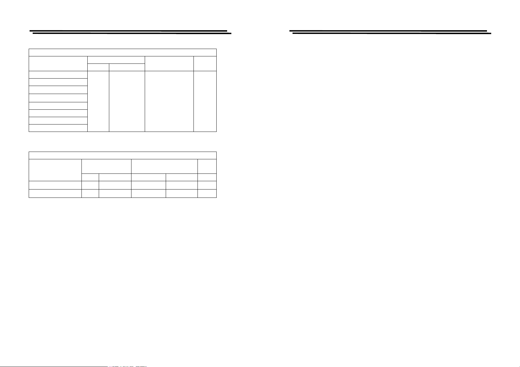
4-5-9. Handler Interface(Only for LCR-826/827/829)
HANDLER
INTERFACEFUNCTION
Signal Name Pin NO.
Start Measurement(I) /I_E_TRIG 24
End of test(O) /O_EOM 23
Data acquisition over , DUT removal OK.(O) /O_INDEX 22
RLC FAIL(O) /O_P_HI
/O_P_LO
/O_P_OVER
No-Go , D or Q Fail /O_S_REJ
/O_S_OVER
19
20
15
21
14
Go , BIN 1 Judgement /O_BIN_ 1 1
Go , BIN 2 Judgement /O_BIN _2 2
Go , BIN 3 Judgement /O_BIN_ 3 3
Go , BIN 4 Judgement /O_BIN_ 4 4
Go , BIN 5 Judgement /O_BIN_ 5 5
Go , BIN 6 Judgement /O_BIN_ 6 6
Go , BIN 7 Judgement /O_BIN_ 7 7
Go , BIN 8 Judgement /O_BIN_ 8 8
Go , BIN 9 Judgement /O_BIN_ 9 9
Go , BIN 10 Judgement /O_BIN_ 10 10
Go , BIN 11 Judgement /O_BIN_ 11 11
Go , BIN 12 Judgement /O_BIN_ 12 12
Go , BIN 13 Judgement /O_BIN_ 13 13
Panel Lock /I_K_LOCK 25
GND GND 16,18
VCC VCC 17
EXIT
Figure 4-12. Programming of memory store/recall. (Cont.)
28
29
Page 18
LCR-800 Series User Manual
Handler Interface Typical Electrical Characteristics
Comparison Signals
/BIN1-/BIN9
/AUX_BIN
/OUT_OF_BIN
/PHI
/PLO
Control Signals
/INDEX
/EOM
* R408~R427 Pull-high Resistor need to be changed.
Handler Interface Typical Electrical Characteristics
Comparison Signals
/EXT_TRIG
/KEY_LOCK
z Input Signals
Voltage Output Rating
Low High
**
≦0.5V +5V~+24V
Input
Low High +5V +12V
≦1V 5V~15V
≦1V 5V~15V
Maximum Current Note
Input Current (Low)
Pull-high Voltage
5mA 12mA
5mA 12mA
5mA
Note
LCR-800 Series User Manual
z Measurement Complete signal:
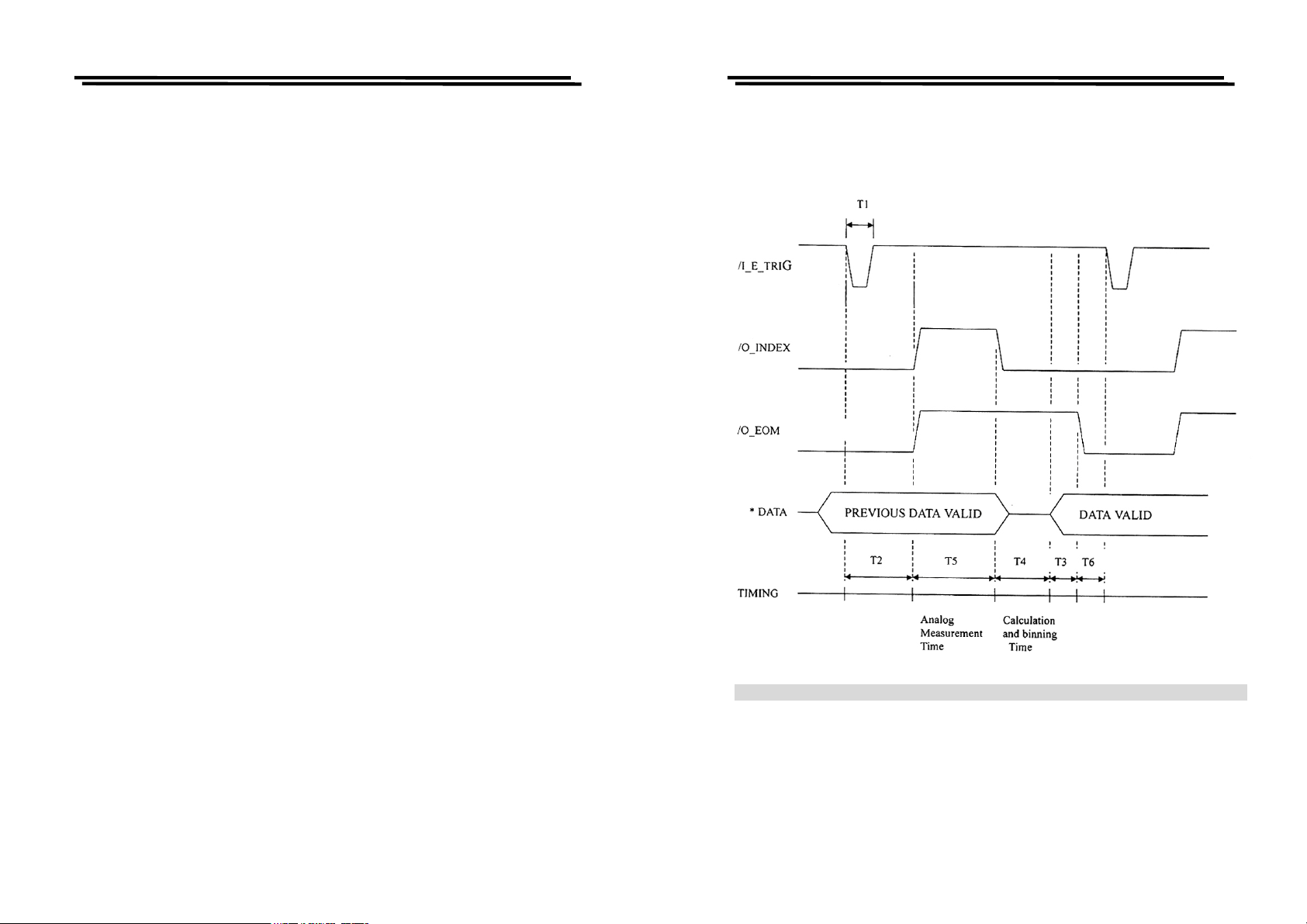
/O_INDEX: This signal will go the low level when analog measurement is
completed and will go the high level when next trigger is
active. The handler can then remove the DUT from the fixture
and replace it with another DUT during the time when
/O_INDEX is at low level.
z Compare Output Signals:
/O_BIN_1- /O_BIN_13 : The GO judgment is active according to the
measured value judgment results (low level),
for example, if the comparator assigns a
component to BIN1, the /O_BIN_1 line will go
the low level till T4 (see Handler Interface
Timing). /O_BIN_2 - /O_BIN_13 are all
inactive (high level).
/O_P_HI: Main parameter failure: When the main parameter is greater than
Max, it will go the low level till T4 (see Handler Interface
Timing).
/I_E_TRIG: This signal is a measurement start signal. To start
measurement by setting low pulse to minimum 5us for
/I_E_TRIG signal. This is a low edge active.
/I_K_LOCK: This signal is to lock all front panel controls. The front panel
is disable when /I_K_LOCK is at low level, and enable
when /I_K_LOCK is at high level.
30
/O_P_LO: Main parameter failure: When the main parameter is lower than
Min, it will go the low level till T4(see Handler Interface
Timing).
/O_P_OVER: It will go the low level when main parameter is greater than
Max or is lower than Min.
/O_S_REJ,/O_S_OVER: It will go the low level when secondary is greater
than D_Max (if MODE=C/D) or is lower than
D_Min.
31
Page 19
LCR-800 Series User Manual
z Judgment Complete Signal
/O_EOM: This signal becomes active (low level) when the measurement
and comparator judgment are completed, and all handler
interface output are stable. It will go the high level when next
trigger Signal (/I_E_TRIG) becomes active (low edge).
LCR-800 Series User Manual
4-5-10. Handler Interface Timing (only for LCR-826/827/829)
32
* DATA: /O_BIN_1-_BIN_13,/O_P_OVER,/O_S_OVER,/O_S_REJ,/O_P_HI,/O_P_LO
33
Page 20
LCR-800 Series User Manual
LCR-800 Series User Manual
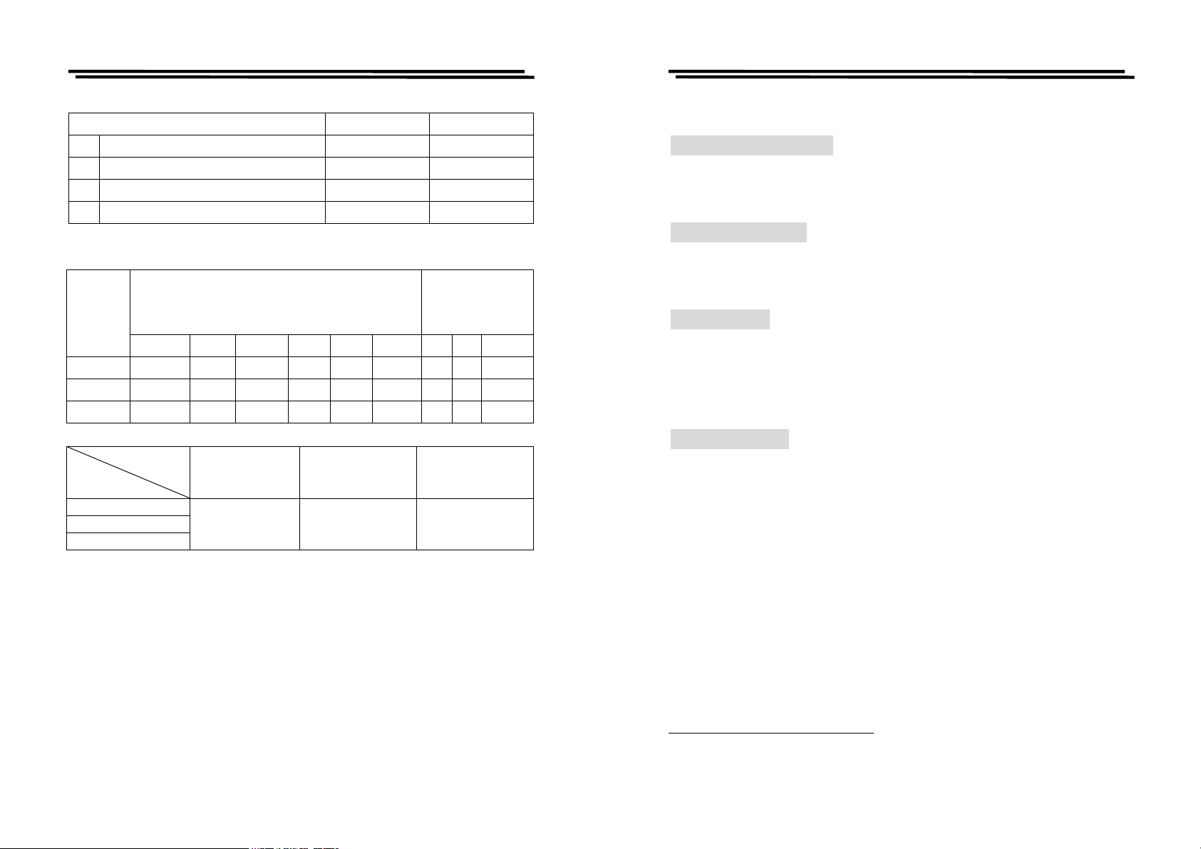
Time Minimum Value Maximum Value
T1
Trigger Pulse Width 5 us —————
T2
Measurement Start Delay Time 140 us —————
T3
/EOM Delay Time After Data Output 5 us —————
T4
Calculation and binning Time 6 ms —————
Trigger Wait Time
SPEED
Analog Measurement Time (T5)
After /EOM
Output (T6)
0.012kHz 0.1kHz 0.12kHz 1kHz 10kHz 100kHz OFF BIN VALUE
SLOW 817ms 901ms 901ms 903ms 873ms 873ms 2ms 4ms 16ms
MEDIUM 817ms 125ms 105ms 59ms 53ms 53ms 2ms 4ms 16ms
FAST 817ms 125ms 103ms 27ms 17ms 17ms 2ms 4ms 16ms
ACCURACY
FAST MEDIUM SLOW
MODEL
LCR-827
LCR-829
0.5% 0.2% 0.1%
LCR-826
5. SPECIFICATIONS
Measurement Parameters:
Inductance (L
Quality Factors (Q), Equivalent Series Resistance (ESR) and Equivalent Parallel
Resistance (EPR), Impedance (|Z|), Phase angle of Impedance [degree] (θ).
Measurement Models:
Six kinds of measurement modes can be selected. Two measurement parameters
measured and displayed simultaneously.
R/Q, C/D, C/R, L/Q, Z/θ, L/R.
Display Ranges:
Primary Display
Inductance (L) : 0.00001mH ~ 99999H
Capacitance (C) : 0.00001pF ~ 99999μF
Resistance (R) : 0.00001Ω~99999kΩ
Absolute of Impedance (Z) : 0.00001Ω~99999kΩ
Secondary Display:
Dissipation factor (D)
Quality factor (Q)
Phase angle of Impedance (degree) : -180.00∘~180.00∘
Equivalent Series Resistance (ESR)+: 0.0001Ω~9999 kΩ
Equivalent Parallel Resistance (EPR)
Dissipation factor (D)
Quality factor (Q)
DELTA % : 0.00001% ~ 99999%
/Lp)*, Capacitance (Cs/Cp), Resistance (Rs/Rp), Dissipation (D),
s
+
**
+
in ppm : 1 ppm ~ 9999 ppm
**
in ppm : 1 ppm ~ 9999 ppm
: 0.0001 ~ 9999
: 0.0001 ~ 9999
+
: 0.0001Ω~9999 kΩ
34
If any of these quantities is negative, the “-“ negative indicator is displayed.
*s=series, p=parallel, ESR=Rs ** with L or R + with C
Note: Only LCR-821 has Z/θ and L/R measurement parameter.
35
Page 21

LCR-800 Series User Manual
LCR-800 Series User Manual
Accuracy:
R, L, C, Z : 0.05%(Basic)+
D, Q :.0005(Basic)+
θ : 0.03∘(Basic)+
*LCR-816/826/827/829 is one fold less accuracy than LCR-817/819.
(LCR-816/826: 0.1%, LCR-827/829: 0.1%, LCR-817/819/821: 0.05%)
+: Please refer to page 39~43 for details.
Test Frequency:
There are 504 test frequencies between 12Hz and 200kHz that can be selected
by using keypad for LCR-821. The frequency range of LCR-819/829 covers
from 12Hz to 100kHz (total test frequencies: 503 points), LCR-817/827 covers
from 12Hz to 10kHz (total test frequencies: 489 points), LCR-816/826 covers
from 100Hz to 2kHz (total test frequencies: 16 points).
Measurement Displays:
The measured results can be shown on the LCD monitor in three ways:
The measured quantities of R/Q, C/D, C/R, L/Q, Z/θ, L/R.
:1. VALUE
*The resolution of primary display (L, C, R or Z) is to be five
digits.
*The resolution of secondary display (D, Q, R with C, or R with
L) is to be four digits.
*The resolution of secondary display (θ) is to be2 digits after
decimal dot.
2. DELTA %
: The DELTA% shows the percent deviation of the measured L,
C, R or Z value from a saved NOMINAL VALUE. The sign of
deviation is indicated.
:3. DELTA
The LCR difference is similar to the DELTA% except that the
deviation is shown in suitable units (ohms, henries, etc.)
Measurement Speed (LCR-816/817/819/821):
SLOW
MEDI
FAST
:
896ms
:
286ms
:
135ms
*For LCR-826/827/829, please refer to 4-5-10. Handler Interface Timing.
Equivalent Circuit:
The L, C, or R equivalent SERIES or PARALLEL circuit can be selected by
keypad.
* When select Z/θ mode, the PARALLEL circuit is invalid. Please refer to 4-4-
2. Series & Parallel Equivalent Circuit from page 12~13 for details.
Measurement Modes:
Two modes are available: AUTO and MANUAL.
“AUTO” mode is measuring continuously, updating the display after each
measurement.
“MANUAL” mode is activated by the START keypad, the measured result is
holding on the LCD monitor until next measurement started.
Average:
The AVERAGE of any number of measurements from 1 to 255 can be made as
desired in either of the two measurement modes.
Test Voltage:
The test voltage range for LCR-817/819/827/829/821 is from 5mV to 1.275V,
each step is 5mV, for LCR-816/826 is from 0.1V to 1.275V, each step is 5mV.
Note: When the test frequency is at 200kHz, the test voltage must be greater
than 100mV.
Memory:
100 memory blocks totally.
DC Bias:
A 2V internal bias can apply to capacitors during measurement.
Up to 30VDC external bias can apply to capacitors during measurement via the
two terminals (located on the rear panel). The applied current should not over
200mA.
* The external bias specified on the rear panel is at 30VDC, actually, it can be
tolerated to 35VDC.
36
37
Page 22
LCR-800 Series User Manual
LCD monitor:
240×128 dot matrix C.C.F.L. back light LCD with adjustable contrast.
Battery:
DC source for system memory and calibration data backup, a replaceable 3V
lithium battery (BR-2/3A type), which probably needs to be replaced after using
for 3 years.
Every time when the battery is replaced, the LCR Meters should be recalibrated.
Operation Environment:
Indoor use,
Altitude up to 2000M
Installation Category II
Pollution Degree 2
Operating temperature: 10℃~50℃, < 85% relative humidity
Storage temperature:-20℃~60℃
AC Power Source:
AC 100~240V, 50Hz~60Hz
Power Consumption:
45 Watts maximum
Fuse Replacement:
Slow-Blow, 3A, 250V
Dimensions:
330mm (W) × 149mm (H) × 437mm (D)
Weight :
5.5 kg
LCR-800 Series User Manual
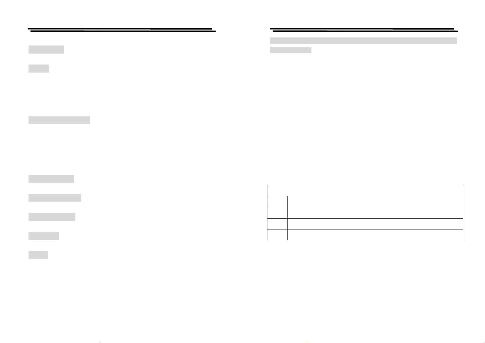
The Error value of LCR-817/819/821 (Double the error value for LCR-
827/829/816/826)
z The formula for primary readout accuracy of C, R, L, and Z.
C: 2 counts±0.03%+0.02%[(1+Ka)# or (X/Ymax )# or (Ymin/X)# ] (1+│D│)(1+Kb+Kc)
R: 2 counts±0.03%+0.02%[(1+Ka)
L: 2 counts±0.03%+0.02%[(1+Ka)#or(X/Ymax)#or(Ymin/X)# ] (1+ 1 /│Q│)(1+Kb+Kc)
|Z|: Ze = Treat R, L or C as the object under test conforming above formula:
example:
When the object under test is C, select:
Ze = 2 counts±0.03%+0.02%[(1+Ka)
When the object under test is R, select:
Ze = 2 counts±0.03%+0.02%[(1+Ka)
When the object under test is L , select:
Ze=2 counts±0.03%+0.02%[(1+Ka)
#
or (X/Ymax )# or (Ymin/X)# ] (1+│Q│)(1+Kb+Kc)
#
or(X/Ymax)#or(Ymin/X)# ] (1+│D│)(1+Kb+Kc)
#
or(X/Ymax)#or(Ymin/X)# ] (1+│Q│)(1+Kb+Kc)
#
or(X/Ymax)#or(Ymin/X)#](1+ 1 /│Q│)(1+Kb+Kc)
z The formulas of secondary readout accuracy for D, Q, and θ.
Error
D with C
Q with R
Q with L
2count±0.0003 + 0.0002[(1+Ka)
2count±0.0003 + 0.0002[(1+Ka)
2count±0.0003 + 0.0002[(1+Ka)
#
or (X/Ymax) # or (Ymin/X) #] (1+│D│+D²)(1+Kb+Kc)
#
or (X/Ymax) # or (Ymin/X) #] (1+│Q│+Q²)(1+Kb+Kc)
#
or (X/Ymax) # or (Ymin/X) #] (1+│Q│+Q²)(1+Kb+Kc)
θ with Z θe=(180/π) x (Ze/100)
# 1. if X≧Ymax, please select (X/Ymax)
≦
2. if X
3. if Ymin<X<Ymax, please select (1+Ka)
Ymin, please select (Ymin/X)
38
4. Ze is impedance error
5.
θe is θ error
39
Page 23
LCR-800 Series User Manual
LCR-800 Series User Manual
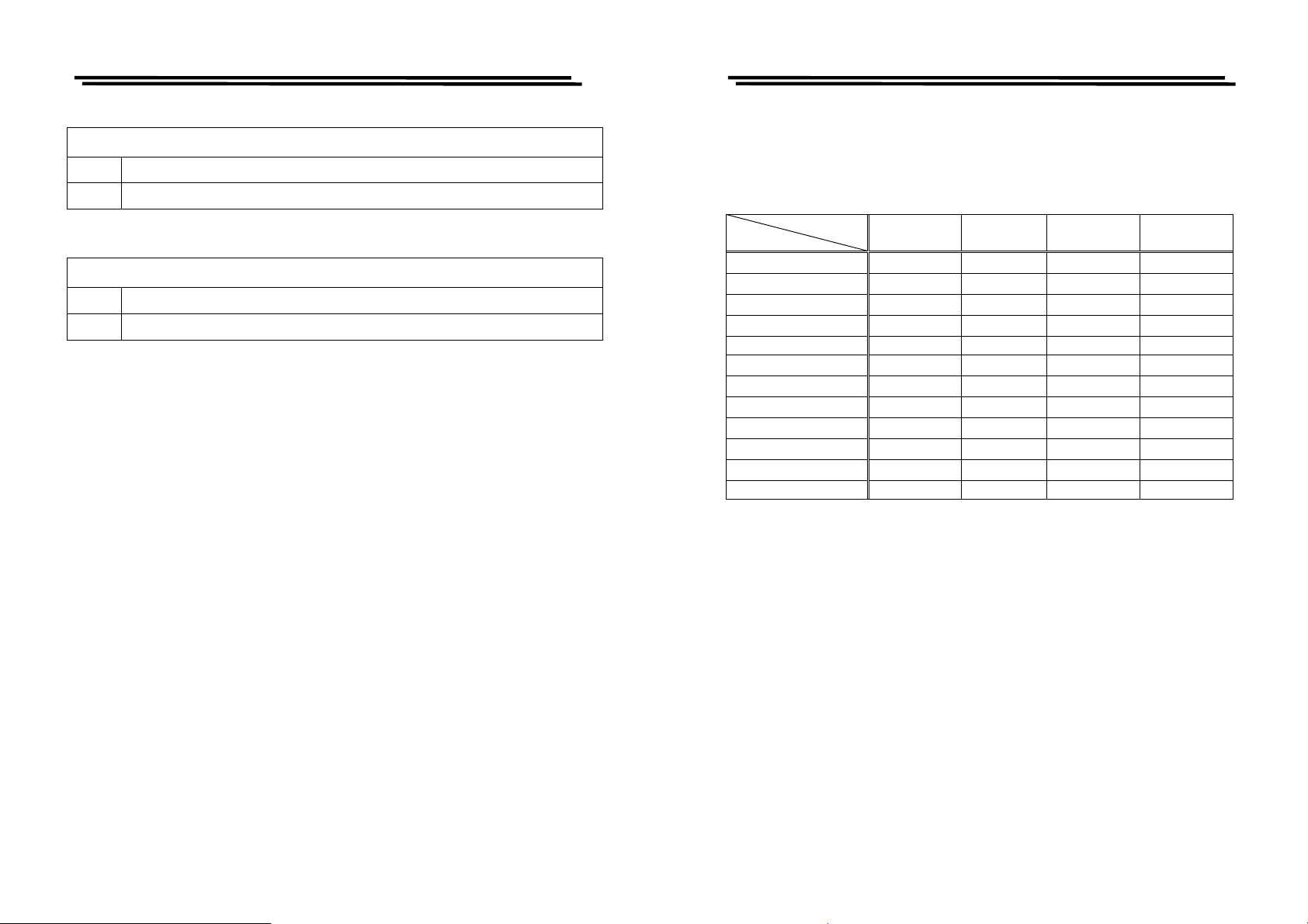
z The formulas for secondary readout accuracy of R with C.
Error
D≧1 2count + 0.02%[(1+Ka)* or (Rx/Rmax)* or (Rmin/Rx)*] (1+ 1/│D│)(1+Kb+Kc)+0.03%
D≦1 2count + 0.02%[(1+Ka)** or (Cx/Cmax)** or (Cmin/Cx)**] (1+ 1/│D│)(1+Kb+Kc)+0.03%
z The formulas for secondary readout accuracy of R with L.
Error
Q≦1 2count + 0.02%[(1+Ka)* or (Rx/Rmax)* or (Rmin/Rx)*] (1+ | Q│)(1+Kb+Kc)+0.03%
Q≧1 2count + 0.02%[(1+Ka)** or (Lx/Lmax)** or (Lmin/Lx)**] (1+| Q│)(1+Kb+Kc)+0.03%
*: 1. If Rx≧Rmax, please select (Rx/Rmax)
2. if Rx
3. if Rmin<Rx<Rmax, please select (1+Ka)
**: 1. If Cx
2. if Cx
3. if Cmin<Cx<Cmax, please select (1+Ka)
≦
Rmin, please select (Rmin/Rx)
≧
Cmax, please select (Cx/Cmax)
≦
Cmin, please select (Cmin/Cx)
Where
Ka: Constant Voltage factor
Rx and Cx are value of the component being tested.
Rmax, Rmin, Cmax and Cmin are ranges constant (refer to Table B).
Table A: (for range 1,2,3) –Kc
Voltage
Frequency
0.012≦F<0.03
0.030≦F<0.1
0.1≦F<0.25
0.25≦F<1
0.03≦V<0.1 0.1≦V<0.25 0.25≦V<11≦V≦1.265
35 12 9 7
30 8 5 3
25 6 3 2
20 5 2 1
114410
1<F≦3
3<F≦6
6<F≦10
10<F≦20
20<F≦50
50<F≦100
15 5 2 1
15 6 3 2
15 8 5 3
20 10 6 5
30 22 18 15
50 40 35 30
200 Nonuse 80 50 45
F: test frequency in kHz
Constant Voltage On , Ka = 2
Constant Voltage Off, Ka = 0
Kb: Test Speed factor
Speed = SLOW , Kb = 0
Speed = MEDIUM , Kb = 3
Speed = FAST ,Kb = 10
Kc: Frequency & RMS Voltage factor (refer to Table A)
X: X is value of the component being tested.
Y: Y is range constant (refer to Table B)
40
41
Page 24
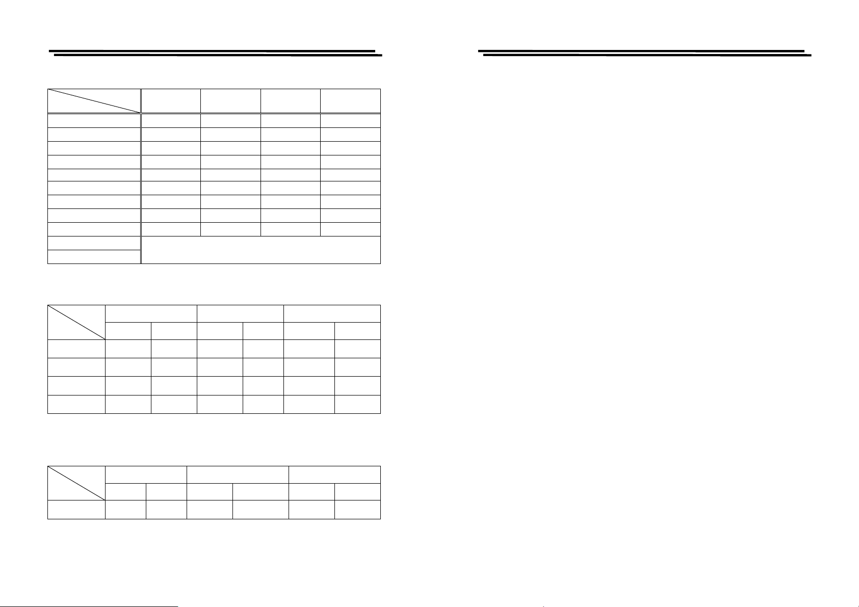
LCR-800 Series User Manual
LCR-800 Series User Manual
Table A: (for range 4)-Kc
Voltage
Frequency
0.012≦F<0.03
0.030≦F<0.1
0.1≦F<0.25
0.25≦F<1
0.03≦V<0.1 0.1≦V<0.25 0.25≦V<11≦V≦1.265
70 20 10 7
50 13 6 3
35942
25621
1 15410
1<F≦3
3<F≦6
6<F≦10
10<F≦20
20<F≦50
50<F≦200
17632
25 15 10 6
60 30 20 15
Not specified 100 65 50
This range is not used above 20kHz
F: test frequency in kHz
Table B-1: Range Hold
Component
Range
Range1 16mH /f 1mH /f 25uF /f 1.6uF /f
Range2 256mH /f 16mH /f 1600nF /f 100nF /f
Range3 4100mH /f 256mH /f 100nF /f 6.4nF /f
Inductor Capacitor Resistor/Impedance
Max Min Max Min Max Min
100Ω 6.25Ω
1.6kΩ 0.1kΩ
25.6kΩ 1.6kΩ
Example of C-D Accuracy Calculation
Measurement Conditions
Frequency: 1 kHz
Test Voltage: 1V
Test Speed=SLOW
Constant Voltage=OFF
R.H=OFF
C measure: 1 μF
D measure: 0.0009
Then:
C Error = 0.03% + [0.02% x (1+ Ka) x (1+0.0009) x (1+Kb+Kc)]
=0.03%+[0.02% x (1+0) x (1.0009) x (1+0+0)]
=0.05%
±2 counts
D Error = 0.0003+[0.0002 x (1+Ka) x (1+0.0009+0.0009²) x (1+Kb+Kc)]
=0.0003+[0.0002 x (1+Ka) x (1+0.0009+(0.0009²) x (1+Kb+Kc)]
=0.0003 + [0.0002 x (1+0) x (1.0009) x (1+0+0)]
=0.0005
±2 counts
Z Error = C Error = 0.05%
θ Error =(180/π) x (Ze/100) =57.3∘x (0.05/100)=0.03∘
Range4* 65H/f 4.1H /f 6400pF /f 400pF /f
f = test frequency in kHz
*: This range is not used above 20kHz
Table B-2: Auto Range
Component
Range
Auto range 65H /f** 1mH /f 25uF /f 400pF /f **
Inductor Capacitor Resistor/Impedance
Max Min Max Min Max Min
**: Above 20kHz, Cmin = 6.4 nF/f ,and Lmax = 4100mH/f
f = test frequency in kHz.
42
410kΩ 25.6kΩ
410kΩ** 6.25Ω**
43
Page 25

LCR-800 Series User Manual
LCR-800 Series User Manual
6. MESSAGE CODE
This section describes the message code for the LCR Meters.
OVER-01
Cause:
1. If the impedance of “Device-under-test” is small than the existing
measurement range of the LCR Meters, the “OVER-01” message will be
displayed on the LCD monitor.
Calculation formula:
Capacitance: XC=1/2
Inductance: XL=2
where f=test frequency in Hz
2. If the inductor of “Device-under-test” is very large at a very high “test
frequency”, the “Resonance effect” will occur and the impedance will
decrease. Hence, the measured value is useless. Meanwhile, an “OVER-01”
message will be displayed on the LCD monitor.
Solution:
1. Turn on the “Constant Voltage” mode (please refer to 4-5-5. Constant
Voltage Source, page 22, for details).
2. Select the less measurement range. Please refer to table B-1: Range Hold,
page 42, in order to reach the exact measurement range. Turn on the “Range
Hold” mode after the measurement range fixed.
π
fL
π
fC
7. MAINTENANCE
This section includes the basic maintenance information for the LCR Meters.
7-1. Cleaning
Remove the AC input power (disconnect and remove the power cord) from the
LCR Meters before attempting to clean the instrument.
To clear the LCR Meters, use soft cloth dampened in a solution of mild detergent
and water. Do not spray cleaner directly onto the instrument, since it may leak
into the cabinet and cause damage.
Do not use chemicals containing benzine, benzene, xylene, acetone, toluene, or
similar solvents.
Do not use abrasive cleaners on any portion of this equipment.
7-2. Battery Replacement
A replaceable 3V lithium battery (BR-2/3A type) supplies the backup power of
non-volatile memory for the LCR Meters. This battery probably needs to be
replaced after using for 3 years.
CAUTION: Danger of explosion if battery is incorrectly replaced.
Replace only with the same or equivalent type recommended by
the manufacturer. Discard used batteries according to the
manufacturer’s instructions.
Note: Both two solutions will reduce the accuracy of the LCR Meters.
44
45
Page 26
LCR-800 Series User Manual
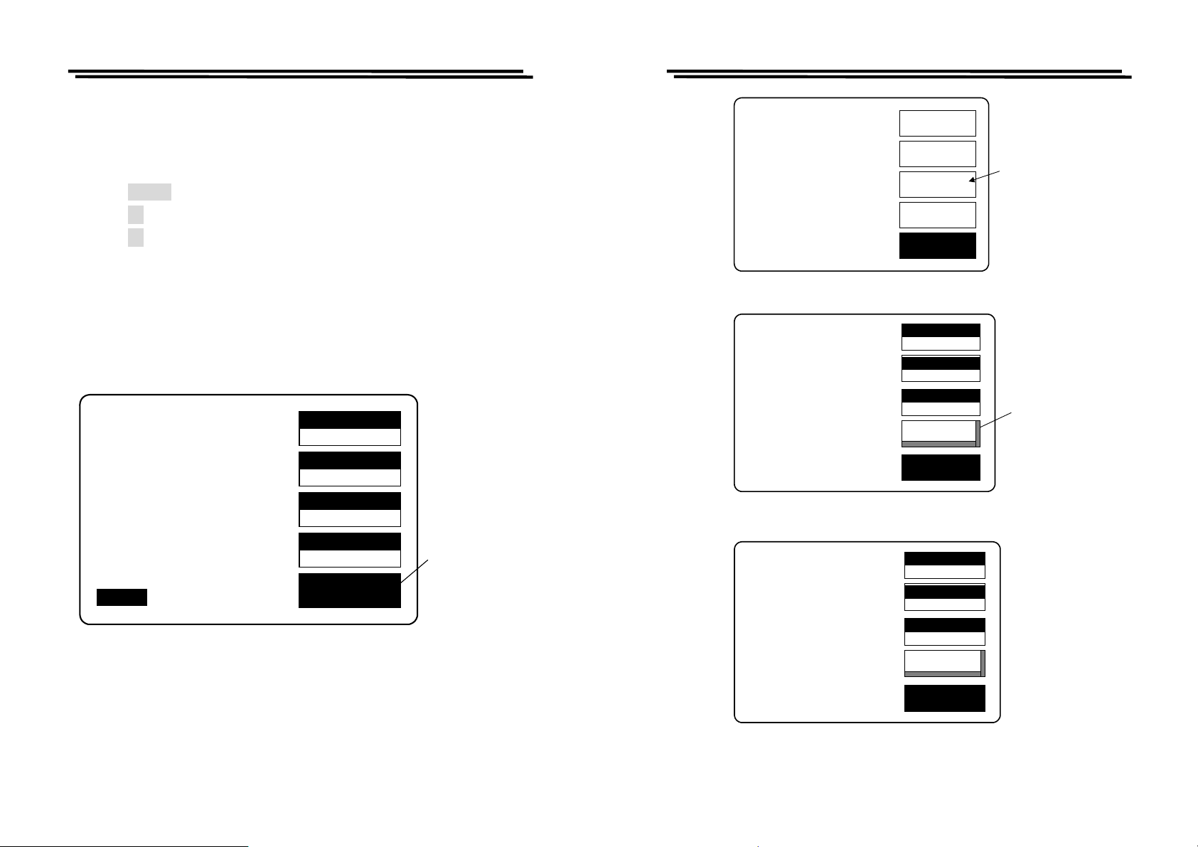
7-3. Recall Calibration
When the measured value is inaccurate, you can use the Recall Calibration
function to rework by proceeding the steps as follows:
z Press MENU key. (Figure 7-1)
z Press F3 key to select “SET PARAMETER” function.(Figure 7-2)
z Press F4 key to select “RECALL CALIBRATION” function.(Figure 7-3)
z Press compound Key 1 to select the “Yes” to start recall calibration.
(Figure 7-4)
z Press compound Key 2 to select the “No” to stop recall calibration.
(Figure 7-4)
※ If the function keys are not active, do not power off and wait another 2
minutes, then try again.
SPEED
C 13.450uF
SLOW
DISPLAY
D .1652
VALUE
MODE
TESTING
F :1.0000 kHz
V :1.000 V
R.H OFF
C.V OFF
AUTO MANU INT.B OFF
C/D
CIRCUIT
SERIES
MENU
Press menu
key
Figure 7-1
LCR-800 Series User Manual
CAP. C/D OFFSET
SET SORT
SET PARAMETER
CALIBRATION
MEMMORY NO: 0
VOLTAGE= 1.000 V
AVERAGE= 1
RECALL CALIBRATION
MEMMORY NO: 0
VOLTAGE= 1.000 V
AVERAGE= 1
RECALL CALIBRATION
Are you sure?(1)Yes
(2)No
SETTING
CALBRAT
Figure 7-2
NOM.VAL
RECALL
Figure 7-3
OFFSET
SORT
EXIT
MEMORY
0
77.000
VOLT
1.000
1
EXIT
MEMORY
MEMORY
0
77.000
VOLT
1.000
NOM.VAL
1
RECALL
EXIT
Press F3 key
to the setting
menu
Press F4 key to
input the recall
function
46
Figure 7-4
47
Page 27
LCR-800 Series User Manual
LCR-800 Series User Manual
8. OPTION 1(BIN Functions, only for LCR-826/827/829)
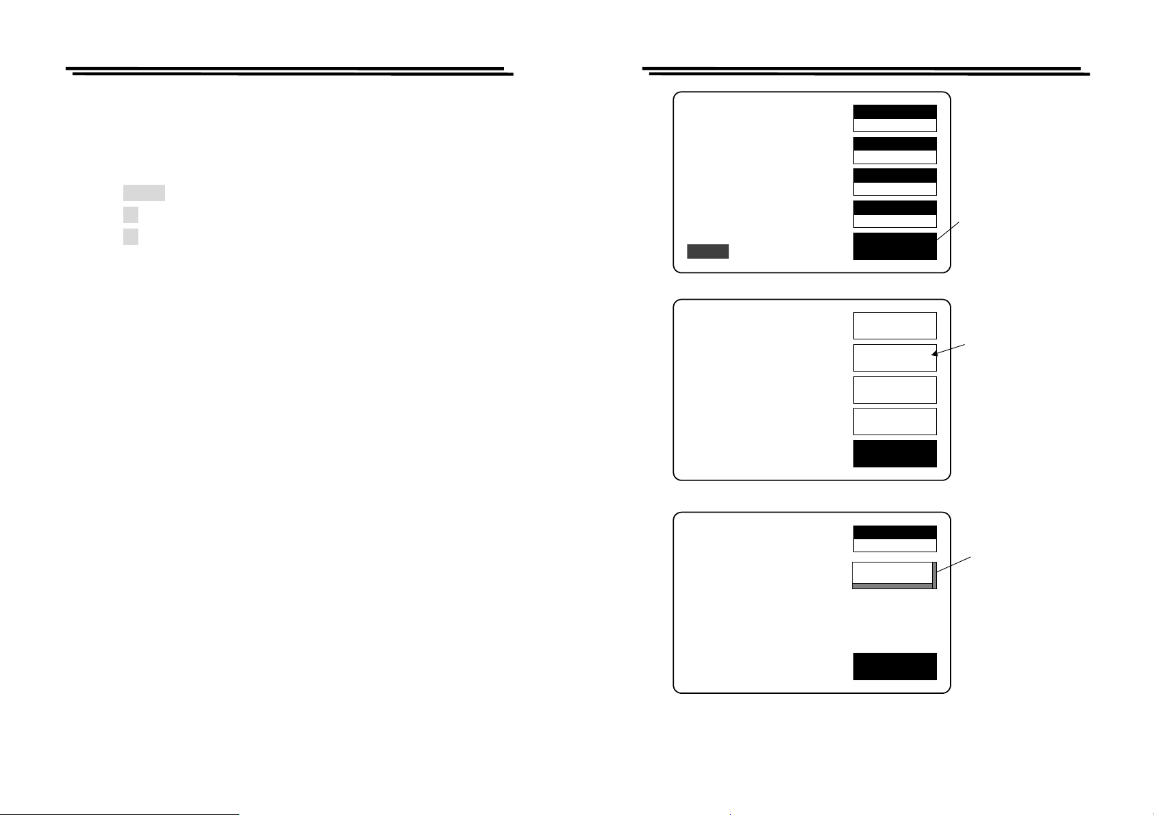
8-1. BIN FUNTIONS for Components Sorting:
Proceed BIN FUNTIONS steps(Figure 8-1):
z Press MENU key.
z Press F2 key to select “SORT” function.
z Press F2 key to select “OPTION1 ” function.
C 13.450uF
D .1652
TESTING
F :1.0000 kHz
V :1.000 V
AUTO MANU INT.B OFF
CAP. C/D OFFSET
SET SORT
SET PARAMETER
CALIBRATION
R.H OFF
C.V OFF
SPEED
SLOW
DISPLAY
VALUE
MODE
C/D
CIRCUIT
SERIES
MENU
OFFSET
SORT
SETTING
CALBRAT
EXIT
Press menu
key
Press F2 key
to the sort
menu
48
NOM.VAL = 77.000pF
OPTION1
NOM.VAL
77.000
HANDLER
EXIT
Figure 8-1.: OPTION 1(BIN FUNTIONS)setting
49
Press F2 key to
input the
option1
function
Page 28
LCR-800 Series User Manual
V
m
M
y
Q
Q
M
V
y
y
M
V
M
V
LCR-800 Series User Manual
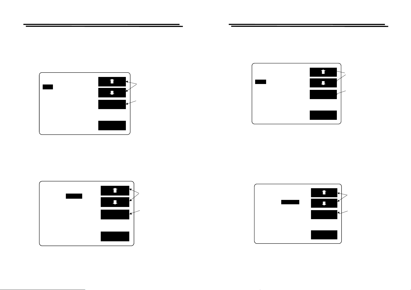
8-2. BIN setting conditions:
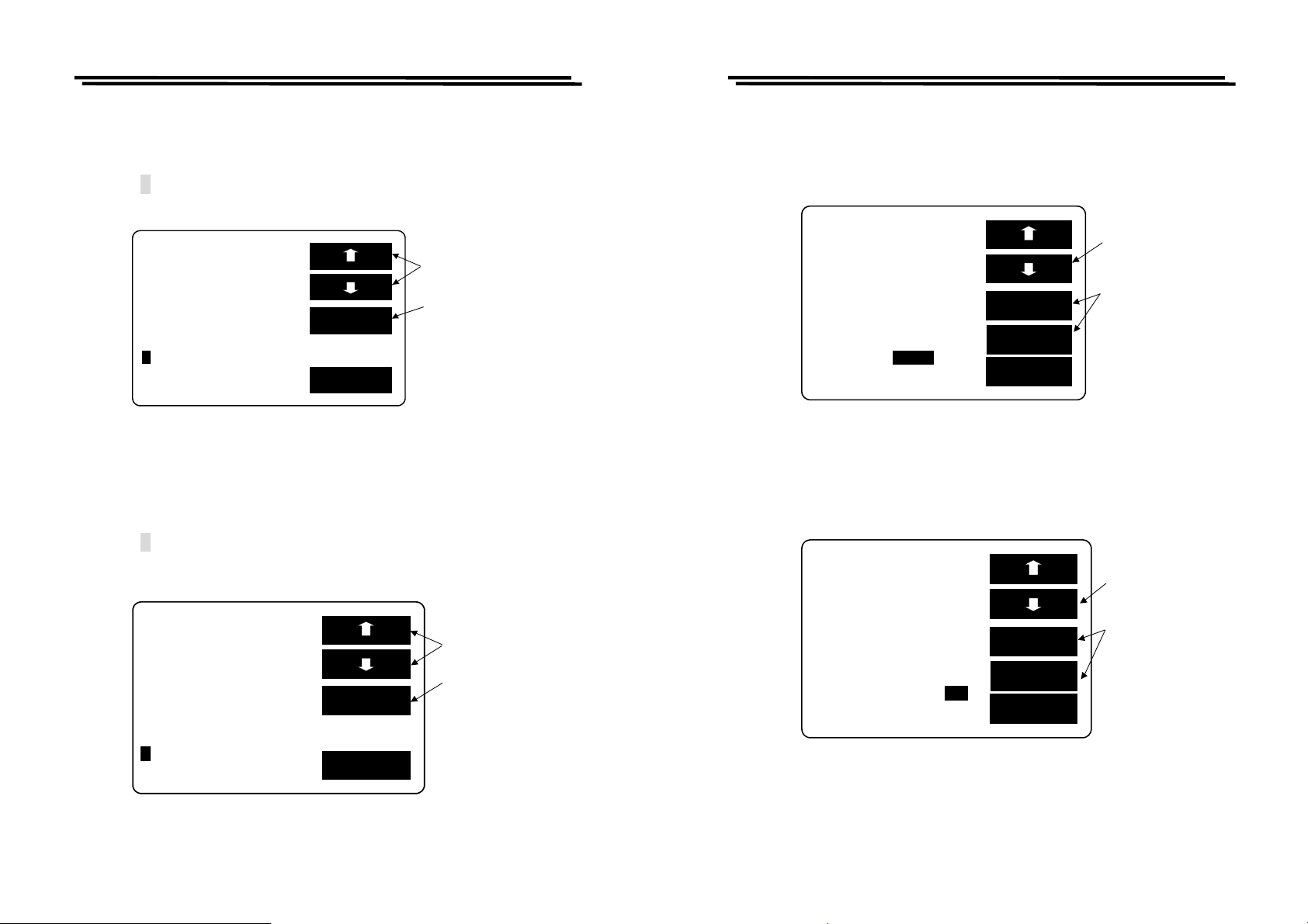
MODE setting:
z Press F1/F2 key to select the white inverted characters “MODE”.
z Press F3 key to select C/D or C/R or L/Q or R/Q shown as Figure 8-2 below.
For further detailed description, please refer to 4-4-1.
SET BIN BIN SUM
:C/D CIRCUIT:SER.
ODE
SPEED:SLOW DISPLAY:BIN
C D
BIN
F:1.0000kHz MANU
:1.000 V INT.B OFF
RANGE:1 C.V : OFF
DELAY:00000mS AVG : 1
SET
EXIT
Press
key to the
mode ite
Press
to the
C/R.L/
ke
.R/
Figure 8-2
CIRCUIT setting:
z Press F1/F2 key to select the white inverted characters “CIRCUIT”.
z Press F3 key to select SER or PAR shown as Figure 8-3 below. For further
details, please refer to 4-4-2
SPEED setting:
z Press F1/F2 key to select the white inverted characters “SPEED”.
z Press F3 key to select FAST, SLOW or MEDI shown as Figure 8-4 below.
For further details, please refer to 4-4-5.
SET BIN BIN SUM
ODE :C/D CIRCUIT:SER.
:SLOW DISPLAY:BIN
SPEED
C D
BIN
F:1.0000kHz MANU
:1.000 V INT.B OFF
RANGE:1 C.V : OFF
DELAY:00000mS AVG : 1
SET
EXIT
Press
key to the
SPEED
key
Press
to the
FAS T/ SL OW/ ME DI
Figure 8-4
DISPLAY setting:
z Press F1/F2 key to select the white inverted characters “DISPLAY”.
z Press F3 key to select BIN, VAL or OFF shown as Figure 8-5 (When the
BIN is selected, BIN1~BIN13 represents PASS, while PHI, PLO, and SREJ
represents FAIL result. The VAL is to display test value while the OFF
represents as non-display.)
※The display speed for above three selections is different from one another.
SET BIN BIN SUM
ODE:C/D :SER.
SPEED:SLOW DISPLAY:BIN
CIRCUIT
C D
BIN
F:1.0000kHz MANU
:1.000 V INT.B OFF
RANGE:1 C.V : OFF
DELAY:00000mS AVG : 1
SET
EXIT
Figure 8-3
50
Press
F1/F2
to the
CIRCUIT
PressF3ke
to the SER.
PA R
ke
SET BIN BIN SUM
ODE:C/D CIRCUIT:SER.
SPEED:SLOW :BIN
DISPLAY
C D
BIN
F:1.0000kHz MANU
:1.000 V INT.B OFF
RANGE:1 C.V : OFF
DELAY:00000mS AVG : 1
SET
EXIT
Press
key to the
DISPLAY
Press
to the
VA L . O F F
key
Figure 8-5
51
Page 29
LCR-800 Series User Manual
M
V
y
y
p
r
M
R
V
r
M
V
t
M
V
LCR-800 Series User Manual
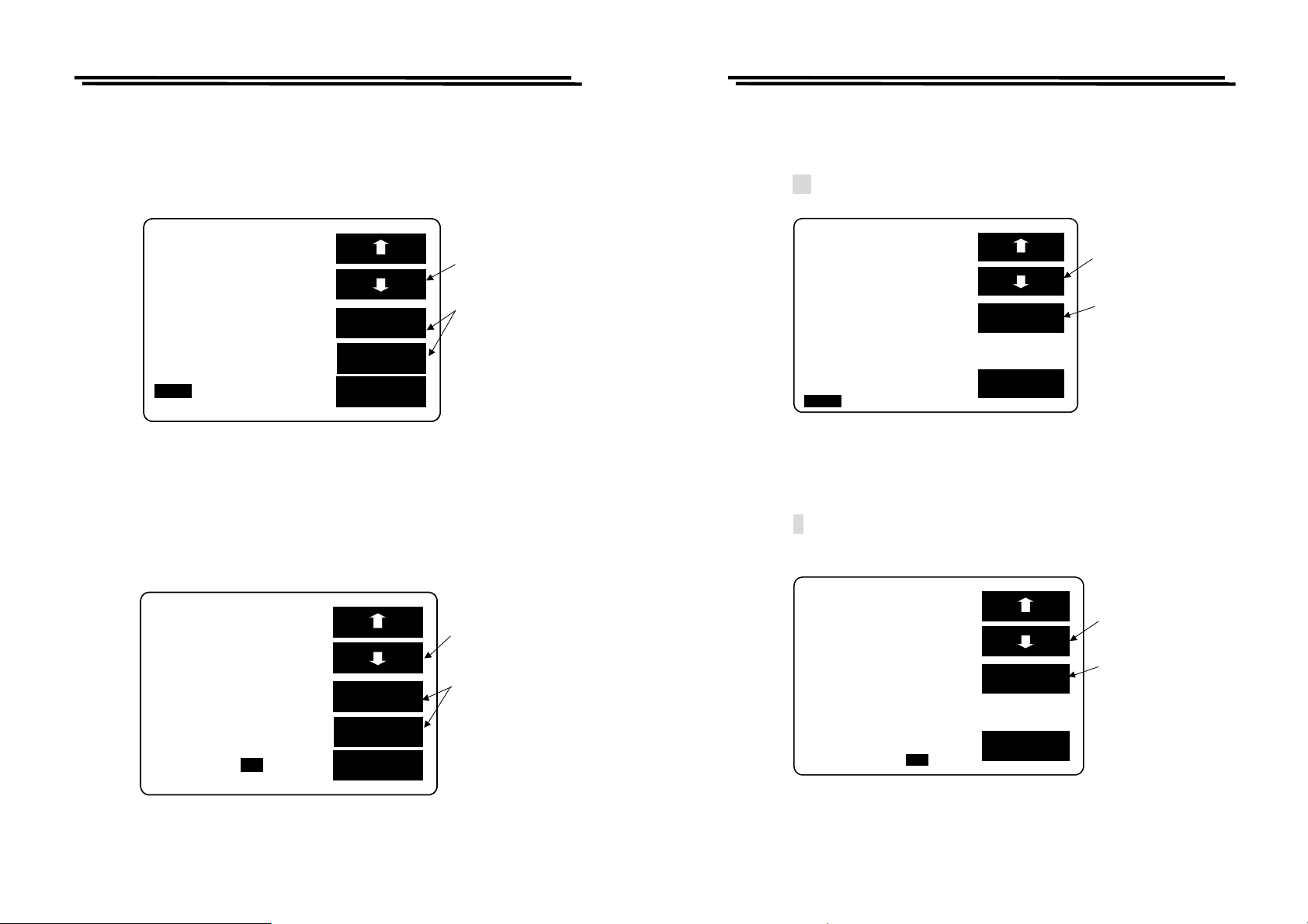
F setting (FREQUENCY):
z Press F1/F2 key to select the white inverted characters “F”.
z Key-in testing frequency through panel keyboard.
z Press ↵ key shown as Figure 8-6 below. For further details, please refer to
4-5-2.
SET BIN BIN SUM
ODE:C/D CIRCUIT:SER.
SPEED:SLOW DISPLAY:BIN
C D
BIN
F
:1.0000kHz MANU
:1.000 V INT.B OFF
RANGE:1 C.V : OFF
DELAY:00000mS AVG : 1
CLR
EXIT
Press F1/F2
ke
to the F
Press F3 ke
to delete the
values in
in erro
ut
Figure 8-6
V setting (VOLTAGE):
z Press F1/F2 key to select the white inverted characters “V”.
z Key-in testing voltage through panel keyboard.
z Press ↵ key shown as Figure 8-7 below. For further details, please refer to
4-5-4.
SET BIN BIN SUM
ODE:C/D CIRCUIT:SER.
SPEED:SLOW DISPLAY:BIN
C D
BIN
F:1.0000kHz MANU
:1.000 V INT.B OFF
RANGE:1 C.V : OFF
DELAY:00000mS AVG : 1
CL
EXIT
Press
key to the V
key
Press
to delete the
values input
in erro
Figure 8-7
INT.B setting:
z Press F1/F2 key to select the white inverted characters “INT.B”.
z Press F3 or F4 key to select INT or ENT shown as Figure 8-8 below. For
further details, please refer to 4-5-1.
SET BIN BIN SUM
ODE:C/D CIRCUIT:SER.
SPEED:SLOW DISPLAY:BIN
C D
BIN
F:1.0000kHz MANU
:1.000 V OFF
RANGE:1 C.V : OFF
DELAY:00000mS AVG : 1
INT.B
INT
EXT
EXIT
Press
Press F3/ F4
key
INT or .EXT
key
to the
INT.B
to selec
Figure 8-8
INT.B ON OFF setting:
z Press F1/F2 key to select the white inverted characters “ON/OFF” of INT.B.
z Press F3 or F4 key to select ON or OFF shown as Figure 8-9 below.
SET BIN BIN SUM
F1/F2 key
ODE:C/D CIRCUIT:SER.
SPEED:SLOW DISPLAY:BIN
Press
to the OFF
C D
Press F3/ F4
BIN
F:1.0000kHz MANU
:1.000 V INT.B:
RANGE:1 C.V : OFF
DELAY:00000mS AVG : 1
OFF
ON
OFF
EXIT
key to select
ON or OFF
Figure 8-9
52
53
Page 30
LCR-800 Series User Manual
M
V
y
y
t
M
V
y
y
t
M
V
r
M
V
r
LCR-800 Series User Manual
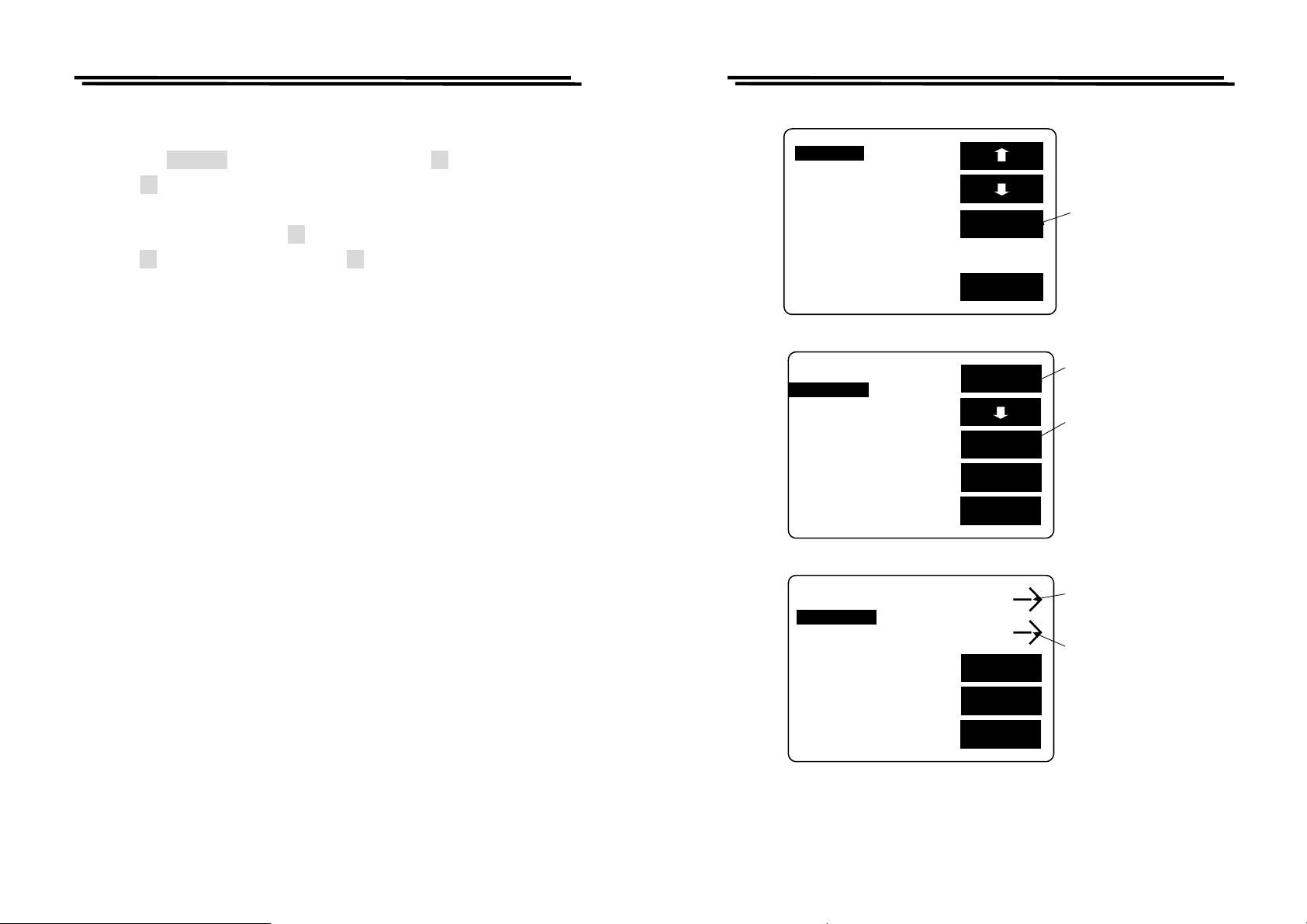
RANGE setting:
z Press F1/F2 key to select the white inverted characters “RANGE”.
z PressF3 or F4 key to select UP or DOWN value within 1~4 range shown as
Figure 8-10 below.
SET BIN BIN SUM
ODE:C/D CIRCUIT:SER.
SPEED:SLOW DISPLAY:BIN
C D
BIN
F:1.0000kHz MANU
:1.000 V INT.B OFF
RANGE:1 C.V : OFF
DELAY:00000mS AVG : 1
UP
DOWN
EXIT
Press F1/F2 ke
to the RANGE
Press F3/F4
ke
to selec
UP or DOWN
Figure 8-10
C.V setting:
z Press F1/F2 key to select the white inverted characters “C.V”.
z Press F3 or F4 key to select ON or OFF shown as Figure 8-11 below. For
further details, please refer to 4-5-5.
DELAY setting:
z Press F1/F2 key to select the white inverted characters “DELAY”.
z Key-in Delay value(0~99999ms) through panel keyboard.
z Press ↵ key. Please refer to Figure 8-12 below.
SET BIN BIN SUM
ODE:C/D CIRCUIT:SER.
SPEED:SLOW DISPLAY:BIN
C D
BIN
F:1.0000kHz MANU
:1.000 V INT.B OFF
RANGE:1 C.V : OFF
DELAY:00000mS AVG : 1
CLR
EXIT
Press
to the DELAY
key
Press
to delete the
values input
in erro
key
Figure 8-12
AVG setting:
z Press F1/F2 key to select the white inverted characters “AVG”.
z Key-in average value through panel keyboard.
z Press ↵ key shown as Figure 8-13 below. For further details, please refer to
4-5-7.
SET BIN BIN SUM
SET BIN BIN SUM
ODE:C/D CIRCUIT:SER.
SPEED:SLOW DISPLAY:BIN
F1/F2
Press
to the C.V
ke
ODE:C/D CIRCUIT:SER.
SPEED:SLOW DISPLAY:BIN
C D
C D
BIN
F:1.0000kHz MANU
:1.000 V INT.B OFF
RANGE:1 C.V : OFF
DELAY:00000mS
AVG: 1
Figure 8-13
BIN
F:1.0000kHz MANU
:1.000 V INT.B OFF
RANGE:1
DELAY:00000mS AVG : 1
C.V: OFF
Figure 8-11
ON
OFF
EXIT
Press F3/F4
to selec
ke
ON or OFF
8-3. BIN Range Setting: Component Sorting Range
54
CLR
EXIT
55
Press
to the AVG
Press
to delete the
values input
key
key
in erro
Page 31
LCR-800 Series User Manual
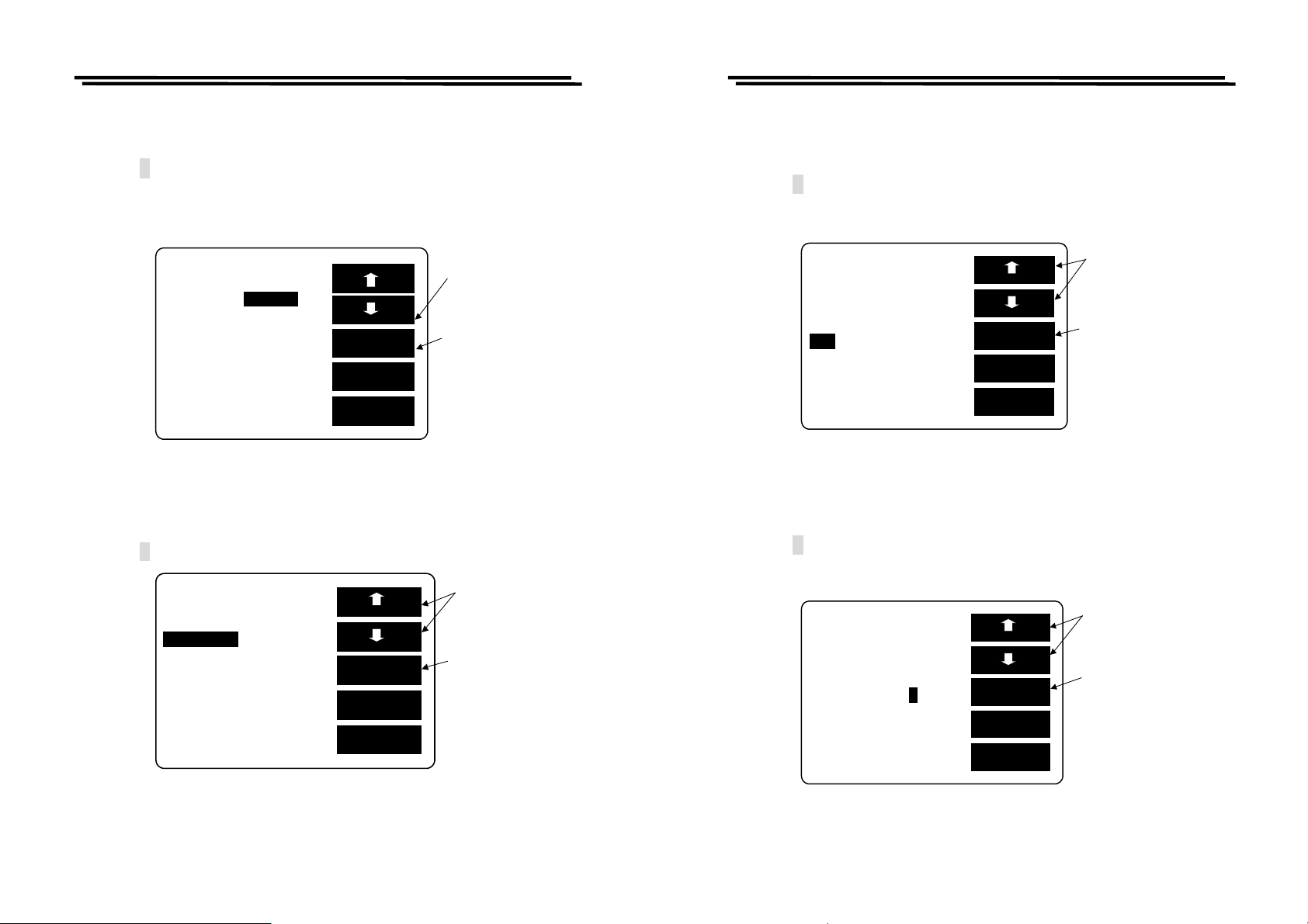
The step for BIN setting: (Please refer to Figure 8-14)
z When the SET BIN inverts to white character, press F3 key.
z Press F3 key to select C or D sorting (The selected is a primary parameter,
the other one is an assistant parameter.)
z BIN clear setting by pressing F1 key.
z Press F1 key to maintain setting, Press F2 key to delete the setting.
LCR-800 Series User Manual
SET BIN
BIN SUM
MODE:C/D CIRCUIT:SER.
SPEED:SLOW DISPLAY:BIN
C D
BIN
F:1.0000kHz MANU
V:1.000 V INT.B OFF
RANGE:1 C.V : OFF
DELAY:00000mS AVG : 1
SET
EXIT
Press F3 key
to the bin
setting
BIN1
SORT BY C
TOt_Bin:13
C_Nom.Val: 15.000pF
Max:16.500pF+:10.0%
Min:13.500pF-:10.0%
D_Max:1.000
D_Min:.0010
BIN1 NO
SORT BY C
TOt_Bin:13
C_Nom.Val: 15.000pF YES
Max:16.500pF+:10.0%
Min:13.500pF-:10.0%
D_Max:1.000
D_Min:.0010
Figure 8-14
BIN
CLR
SORT
D
NEXT
BIN
EXIT
SORT
D
NEXT
BIN
EXIT
Press F1 key
for clear
setting
Press F3 key
to sort C or D
Press F1 key
for non-clear
Press F2 key
for clear
setting
56
57
Page 32
LCR-800 Series User Manual
M
M
N
y
r
_
M
M
_
R
N
r
_
M
M
_
R
N
y
p
r
_
M
M
_
R
N
r
LCR-800 Series User Manual
Tot_BIN setting:
z Press F1/F2 key to select the white inverted characters “Tot_Bin”.
z Key-in needed BIN value through panel keyboard.
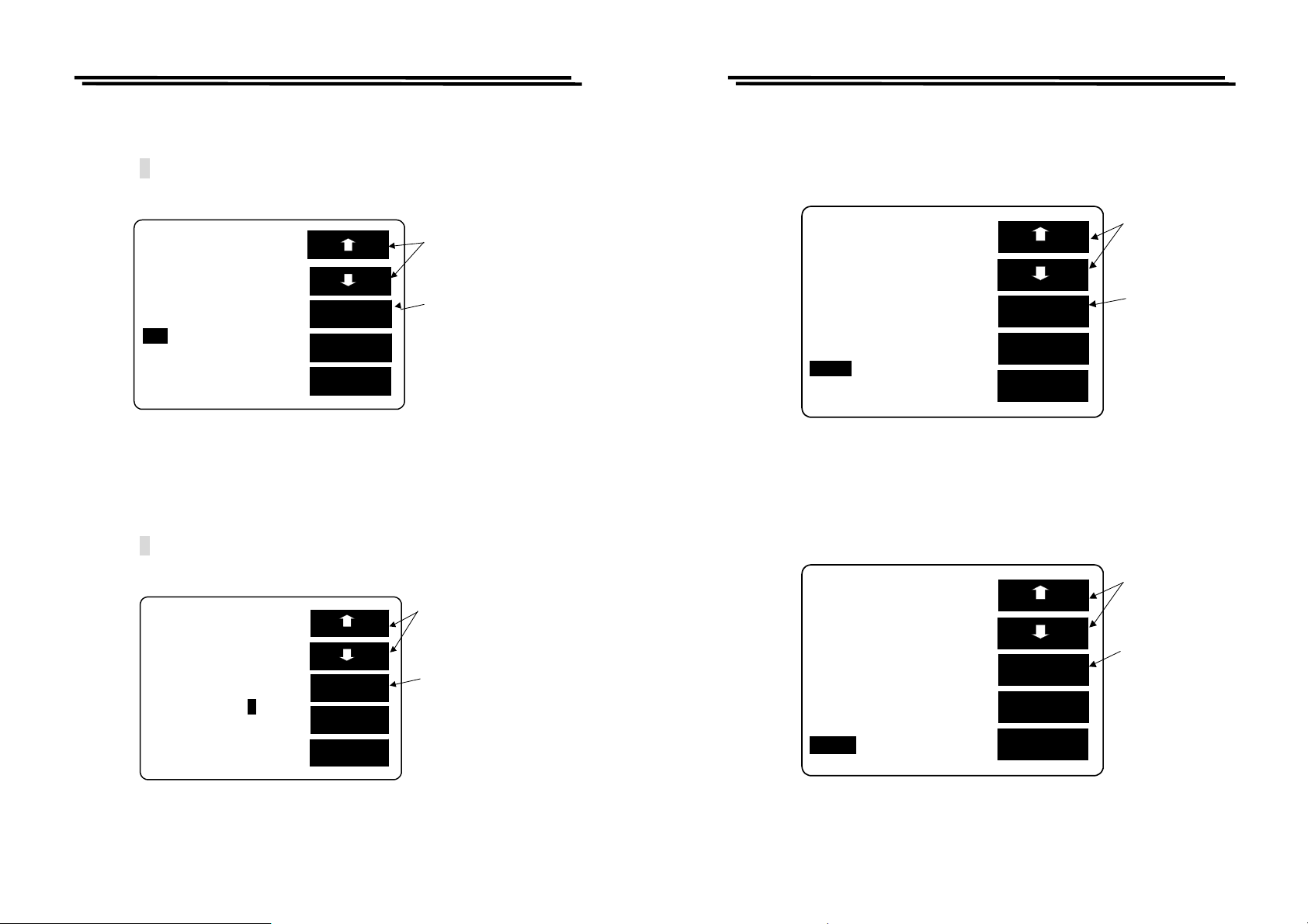
z Press ↵ key. Please refer to Figure 8-15 below.
Note: Tot_Bin setting: It can select ascending from 1 to 13 BIN the most.
For example: If BIN1 sorting range is at
be larger than
±5%, the rest can be done accordingly.
BIN 1
SORT BY C
Nom.Val: 15.000pF
C
ax:16.500pF+:10.0%
in:13.500pF-:10.0%
D_Max:1.000
D
Min:.0010
Tot Bin:13
±5%, then BIN2 sorting range must
CL
EXT
BIN
EXIT
Press
Tot Bi n
Press
can delete the
values input
in erro
to the
key
key
Figure 8-15
C_Nom.Val setting:
z Press F1/F2 key to select the white inverted characters “C_Nom.Val”.
z Key-in Nominal Value through panel keyboard.
z Press ↵ key. Please refer to Figure 8-16 below.
Press
BIN 1
SORT BY C TOt_Bin:13
key to the
CNom.Val
C_Nom.Val: 15.000pF
ax:16.500pF+:10.0%
in:13.500pF-:10.0%
D_Max:1.000
D_Min:.0010
CLR
EXT
BIN
EXIT
Press F3 ke
can delete the
values input
in erro
Figure 8-16
Max setting:
z Press F1/F2 key to select the white inverted characters “Max”.
z Key-in SORT Max value through panel keyboard.
z Press ↵ key. Please refer to Figure 8-17 below.
※After the value is input, it will proceed conversion of +% automatically.
Press F1/F2
BIN 1
SORT BY CTOt_Bin:13
C
Nom.Val:15.000pF
ax:16.500pF+:10.0%
in:13.500pF-:10.0%
Max:1.0000
D
D_Min:0.00010
CL
EXT
BIN
EXIT
key to the
Max
Press F3 ke
can delete
the values
in
ut in erro
Figure 8-17
“+” setting:
z Press F1/F2 key to select the white inverted characters “+”.
z Key-in the largest percentage of SORT Nominal Value through the panel
keyboard.
z Press ↵ key. Please refer to Figure 8-18 below.
※After the value is input, it will proceed conversion of Max automatically.
Press F1/F2
BIN 1
SORT BY CTOt
Bin:13
key to the
+
C_Nom.Val: 15.000pF
key
ax:16.500pF+:10.0%
in:13.500pF-:10.0%
Max:1.0000
D
D_Min:0.00010
CL
EXT
BIN
EXIT
Press F3
to delete the
values input
in erro
Figure 8-18
58
59
Page 33
LCR-800 Series User Manual
_
M
M
_
R
N
3
r
_
M
M
_
R
N
r
M
M
y
_
N
y
put
r
M
M
y
_
N
y
put
r
LCR-800 Series User Manual
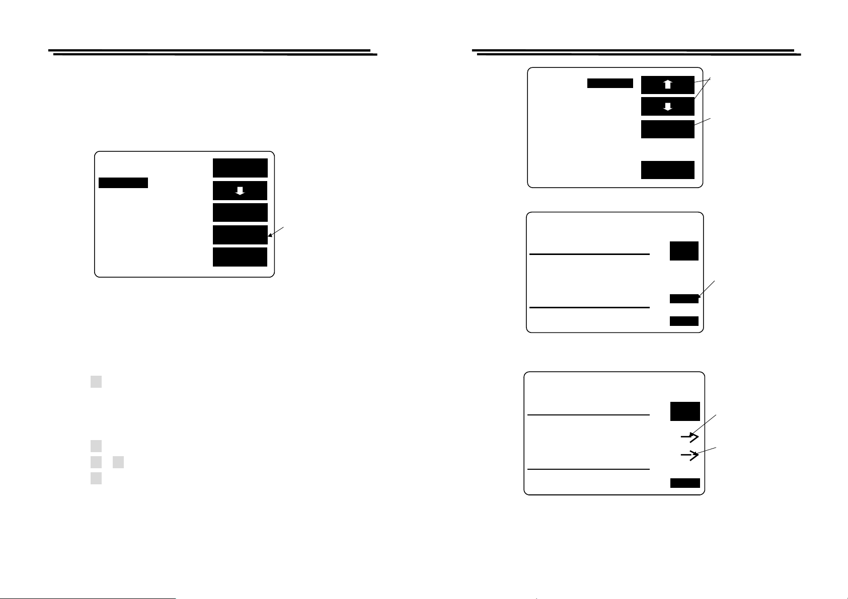
Min setting:
z Press F1/F2 key to select the white inverted characters “Min”.
z Key-in SORT Min value through panel keyboard.
z Press ↵ key. Please refer to Figure 8-19 below.
※After the value is input, it will proceed conversion of -% automatically.
BIN 1
SORT BY C TOt
Bin:13
PressF1/F2
key to the Min
C_Nom.Val:15.000pF
key
F
ax:16.500pF+:10.0%
in:13.500pF-:10.0%
Max:1.0000
D
D_Min:0.00010
CL
EXT
BIN
EXIT
Press
to delete the
values input
in erro
Figure 8-19
“-” setting:
z Press F1/F2 key to select the white inverted characters “-”.
z Key-in the smallest minus percentage of SORT Nominal Value through the
panel keyboard.
z Press ↵ key. Please refer to Figure 8-20 below.
※After the value is input, it will proceed conversion of Min automatically.
Press
F1/F2
BIN 1
SORT BY CTOt
Bin:13
C_Nom.Val: 15.000pF
ax:16.500pF+:10.0%
in:13.500pF-:10.0%
Max:1.0000
D
D_Min:0.00010
CL
EXT
BIN
EXIT
key to the
-
key
Press F3
to delete the
values input
in erro
D_Max setting:
z Press F1/F2 key to select the white inverted characters “D_Max”.
z Set the largest D value of secondary parameter. Please refer to Figure 8-21
below.
Press F1/F2
to the
BIN 1
SORT BY C TOt_Bin:13
ke
Max
D
C_Nom.Val: 15.000pF
ax:16.500pF+:10.0%
in:13.500pF-:10.0%
D_Max:1.0000
D_Min :0.00010
CLR
EXT
BIN
EXIT
PressF3ke
to delete the
values in
in erro
Figure 8-21
D_Min setting:
z Press F1/F2 key to select the white inverted characters “D_Min”.
z Set the smallest D value of secondary parameter. Please refer to Figure 8-22.
Press F1/F2
to the
BIN 1
SORT BY C TOt_Bin:13
ke
Min
D
C_Nom.Val: 15.000pF
Press F3 ke
ax:16.500pF+:10.0%
in:13.500pF-:10.0%
D_Max :1.0000
D_Min:0.00010
CLR
EXT
BIN
EXIT
to delete the
values in
in erro
Figure 8-20
60
Figure 8-22
61
Page 34
LCR-800 Series User Manual
M
M
t
N
LCR-800 Series User Manual
The other BIN setting:
z When the BIN 1 setting is finished, press F4 key to continue the BIN 2
setting until all the Tot BIN setting is completed (BIN1~BIN13 the most),
please refer to Figure 8-23.
BIN 1
SORT BY C TOt_Bin:13
C_Nom.Val: 15.000pF
ax:16.500pF+:10.0%
in:13.500pF-:10.0%
D_Max:1.0000
D_Min:0.00010
BIN
CLR
SORT
D
EXT
BIN
EXIT
PressF4 key
to the nex
BIN
Figure 8-23
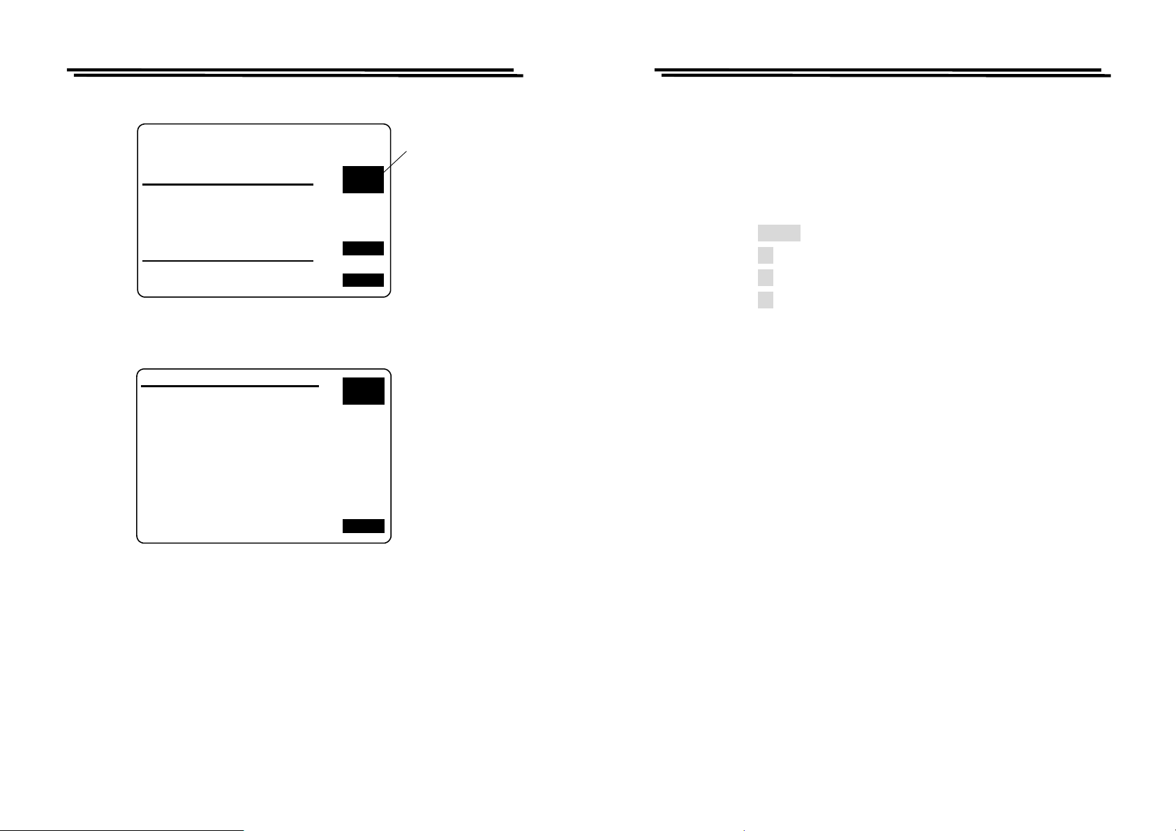
TEST RESULT Display Summing-up:
z Press F1/F2 key to select the white inverted characters “BIN.SUM” (Figure
8-24).
z Press F3 key to see the test result.
※ Sorting judging rule: To check whether the secondary parameter is within
the setting range, if not, just display SREJ instead of judging the primary
parameter, if yes, continue to proceed primary parameter sorting.
z Press F4 key to delete test result (Figure 8-25).
z Press F3 orF4 key to select delete or non-delete test result (Figure8-26).
z Press F2 key to see next page of test result (Figure 8-27, 8-28).
SET BIN
MODE:C/D CIRCUIT:SER
SPEED:SLOW DISPLAY:BIN
BIN SUM
C D
BIN
F :1.0000kHz MANU
V :1.000 V INT.B OFF
RANGE:1 C.V : OFF
DELAY:00000mS AVG : 1
SET
EXIT
Figure 8-24
SORT BY C NOM_VAL:15.000pF
D_MIN: .0010 D_MAX: 1.000
TEST RESULT
FAIL_ITEM TOTAL
PHI ( C >MAX )
PLO ( C <MIN )
SREJ( D NG ) 2
TOTAL 2
PASS_ITEM
BIN 1 - BIN 13
Figure 8-25
SORT BY C NOM_VAL:15.000pF
D_MIN: .0010 D_MAX: 1.000
TEST RESULT
FAIL_ITEM TOTAL
PHI ( C >MAX )
PLO ( C <MIN )
SREJ( D NG ) 2 YES
TOTAL 2
NO
PASS_ITEM
BIN 1 - BIN 13
NEXT
PAGE
CLR.
EXIT
NEXT
PAGE
EXIT
PressF1.F2
key to the
BIN SUM
Press F3 key
to the test
result
Press F4 to
CLR
Press F3 to
delete the
testing data
Press F4 to
maintain the
testing data
Figure 8-26
62
63
Page 35
LCR-800 Series User Manual
SORT BY C NOM_VAL:15.000pF
D_MIN: .0010 D_MAX: 1.000
TEST RESULT
FAIL_ITEM TOTAL
PHI ( C >MAX )
PLO ( C <MIN )
SREJ( D NG ) 2
TOTAL 2
PASS_ITEM
BIN 1 - BIN 13
BIN MIN pF MAX pF TOTAL
1 13.500 16.500 999999
2 12.750 17.250 999999
3 12.000 18.000 999999
4 11.250 18.750 999999
5 10.500 19.500 999999
6 9.750 20.250 999999
7 9.000 21.000 999999
8 8.250 21.750 999999
9 7.500 22.500 999999
10 6.750 23.250 999999
11 6.000 24.000 999999
12 5.250 24.750 999999
13 4.500 25.500 999999
Figure 8-27
NEXT
PAGE
CLR.
EXIT
LAST
PAGE
EXIT
Press F2 to
next page
LCR-800 Series User Manual
9. OPTION 2 (RS-232C: option for LCR-816/817/819, standard
for LCR-821)
9-1. On-line Procedure
1) Power on the LCR METER.
Power on the RS232 function of LCR METER. With the steps as
2)
follows (Figure 1):
z Press MENU key.
z Press F2 key to select “SORT” function.
z Press F3 key to select “OPTION 2” function.
z Press F1 key to select “RS232” ON.
3)
Run PC LCR-VIEWER Program.
4)
Check the contents of the Message area under the LCR-VIEWER to
make sure the Online Procedure has been well done. If not, select the
setting items above the LCR-VIEWER to change the Com port and
make connection again until it is online. Please refer to Figure 9-2, 9-
3, 9-4.
Figure 8-28
64
65
Page 36
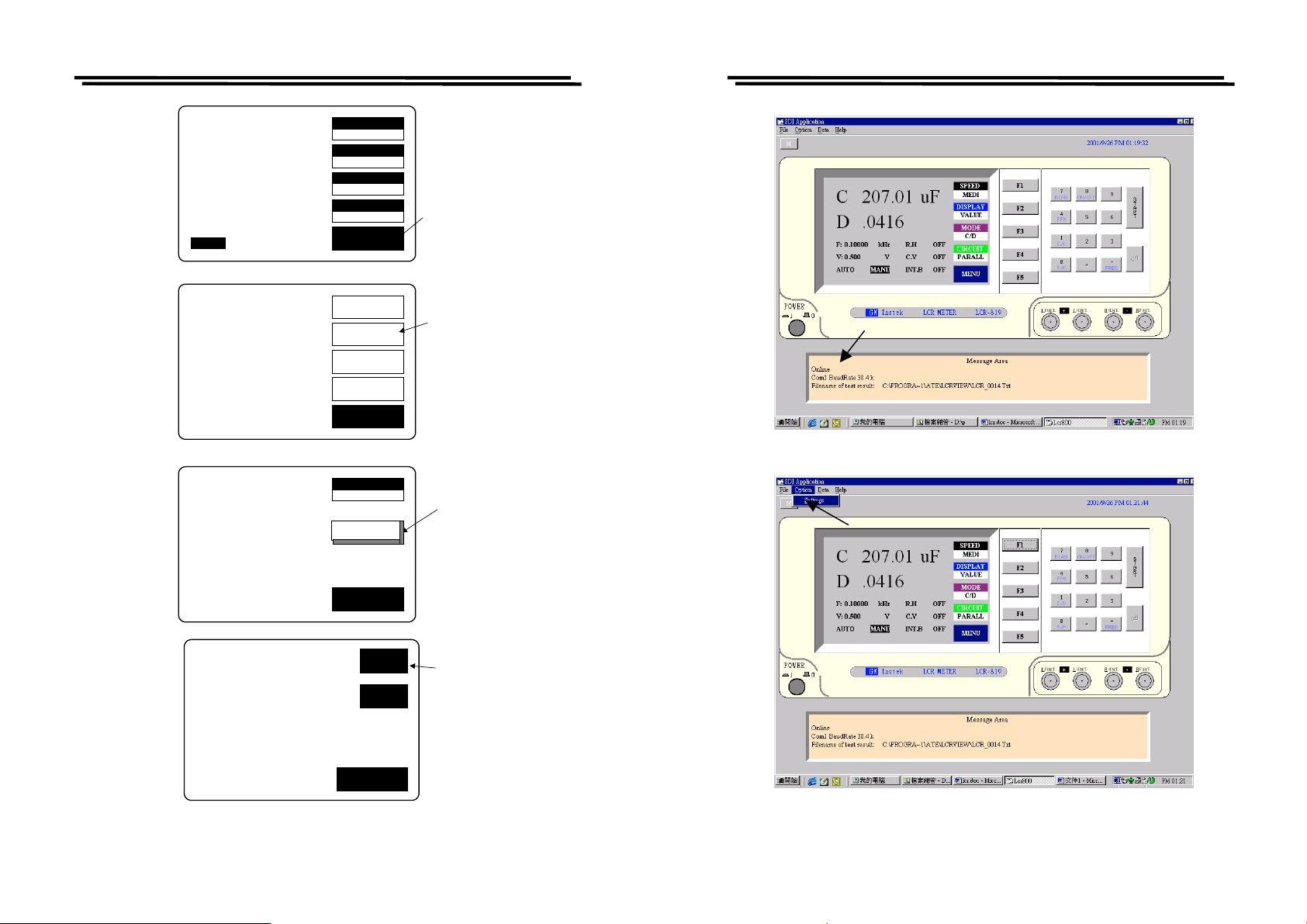
LCR-800 Series User Manual
C 13.450uF
D .1652
F :1.0000 kHz
V :1.000 V
AUTO MANU INT.B OFF
TESTING
R.H OFF
C.V OFF
SPEED
SLOW
DISPLAY
VALUE
MODE
C/D
CIRCUIT
SERIES
MENU
Press menu
key
LCR-800 Series User Manual
CAP. C/D OFFSET
SET SORT
SET PARAMETER
CALIBRATION
NOM.VAL = 77.000pF
OPTION2
RS232 INTERFACE:ON
OFFSET
SORT
SETTING
CALBRAT
EXIT
NOM.VAL
77.000
RS232
EXIT
OFF
ON
Press F2 key
to the sort
menu
Press F3 key to
input the
option2
function
Press F1 key
to the RS232
ON
Figure 9-2
Figure 9-1
66
EXIT
Figure 9-3
67
Page 37
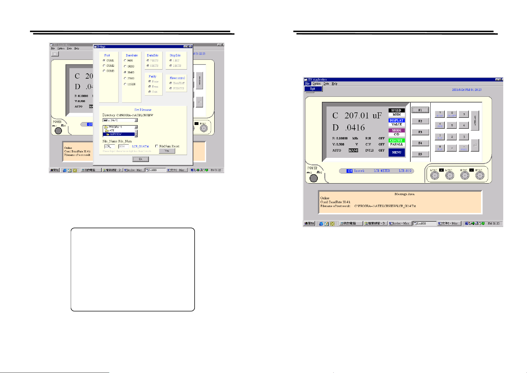
LCR-800 Series User Manual
LCR-800 Series User Manual
9-2. RS232 VIEWER Software Operation
1) File
Press Exit(Figure 9-6), or press Power to leave the program.
Figure 9-4
5) After online, the picture of LCR Meter will be switched to “RS232
ONLINE”, please refer to Figure 9-5.
RS232 ONLINE
Figure 9-5
68
Figure 9-6
69
Page 38
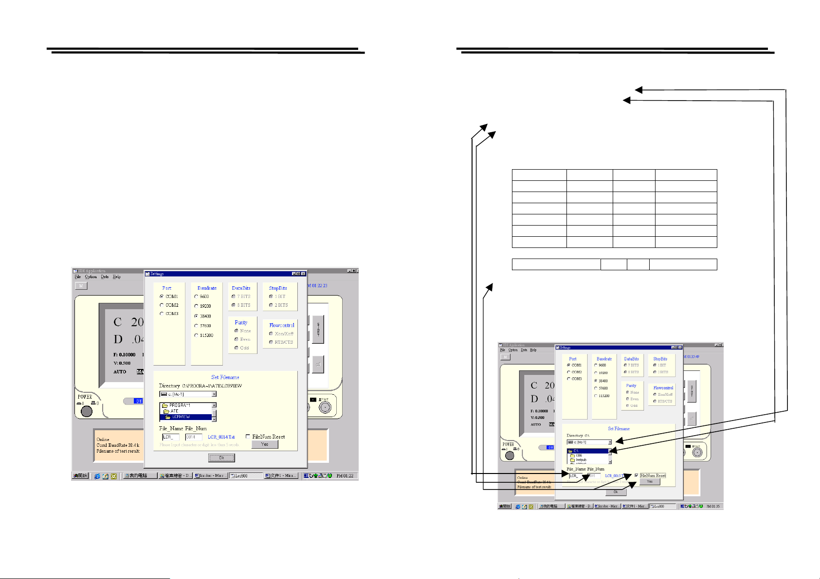
LCR-800 Series User Manual
t
m
t
t
t
t
t
t
_
t
LCR-800 Series User Manual
2) Option
Settings
Port: There are three Ports available for selection including
Com1, Com2 and Com3. The default value is Com1.
Baudrate: After online, there are five Baudrates available for
selection including 9600, 19200, 38400, 57600 and
115200. The default value is 38400
。
DataBits: There are 8 bits of Data bits and User can not change it.
Parity: None. User can not change it.
StopBits: There is only 1 Bit of StopBits, and User can not change it
(Figure 9-7).
3) Set Filename
This filename setting is the route for saving test result.
Driver: Set driver
。
Directory: Set directory。
File_Name: Set file name with 4 alphabets or 4 numbers input.
File_Num: Set 4 codes of file numbers from 0001 to 9999. When
the test results data reaches to the number of 10000 can
be stored with a file number.
Test Resul
File_Name File_Nu
Filename
1-10000 LCR_ 0001 LCR_0001.Tx
10001-20000 LCR_ 0002 LCR_0002.Tx
20001-30000 LCR_ 0003 LCR_0003.Tx
30001-40000 LCR_ 0004 LCR_0004.Tx
40001-50000 LCR_ 0005 LCR_0005.Tx
50001-60000 LCR_ 0006 LCR_0006.Tx
|
99980001-99990000 LCR
9999 LCR_9999.Tx
FileNum Reset (refer to the following figure): File_Num is 0001.
Ps. File_Num will be continued from last file number of test result. If
last file number is end at 0006, next file number is started from 0007
when re-power on the unit.
If want to start from 0001, reset the FileNum (refer to Figure 9-8).
Figure 9-7
Figure 9-8
70
71
Page 39
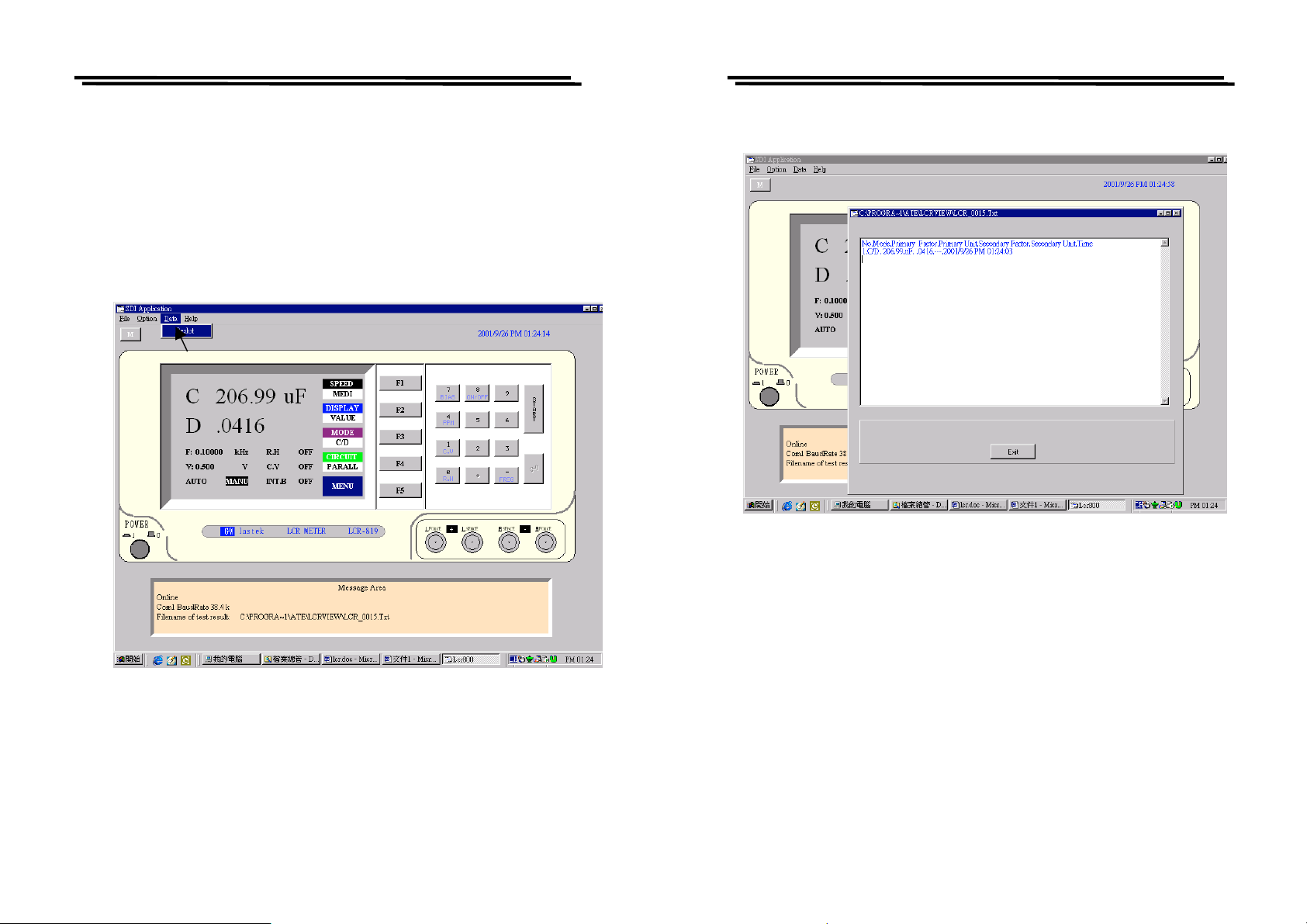
LCR-800 Series User Manual
4) Data
Result :
Display test results. When the test results data reaches to the
number of 10000 will be stored in a file automatically. If want
to store the data less than the number of 10000, must exit the
LCR-VIEWER first (the data can be stored automatically),
then execute again the LCR-VIEWER to start another
counting of test result data. Please refer to Figure 9-9 and 9-
10.
LCR-800 Series User Manual
Figure 9-9
72
Figure 9-10
73
Page 40

LCR-800 Series User Manual
9-3. The Configuration of Cable
Use the cable between DCE and DTE.
9 PIN D-SUB FEMALE to Computer (D-SUB1)
9 PIN D-SUB FEMALE to LCR Meter (D-SUB2)
D-SUB 1 D-SUB 2
Receive Data 2 3 Transmit Data
Transmit Data 3 2 Receive Data
Data Terminal Ready 4 6+1 Data Set Ready + Carrier
Detect
System Ground 5 5 System Ground
Data Set Ready + Carrier
6+1 4 Data Terminal Ready
Detect
Request to Send 7 8 Clear to Send
Clear to Send 8 7 Request to Send
74
 Loading...