

Goodwe SDT8-15KW, SDT12-15KW, SDT4-6KW User Manual
SEMS Portal app
SEMS Portal website
www.sems.portal.com
Company’s offcial website
SDT SERIES USER MANUAL
340-00220-01
SOLAR INVERTER
光伏并网逆变器

1 Symbols
01
2 Safety
3 Installation
3.1 Mounting instruction
3.2 Inverter Overview and Package
3.3 Inverter Installation
3.4 Electrical Connection
4 System Operation
4.1 Indicator Lights
4.2 User Interface and Use of the Display
4.3 Error message
4.4 Wi-Fi Reset & Wi-Fi Reload
4.5 Special Adjustable Setpoints
5 Troubleshooting
01
02
02
02
03
05
11
11
11
16
16
16
17
6 Technical Parameters
7 Certificates
8 Maintenance
18
20
20

1 Symbols
There is a risk of injury due to
improperly handle the device.
Danger of high voltage and
electric shock.
Danger of hot surface! Do not touch
the hot surface when the device is
running.
8
Component of product can be
recycled
This surface is upward, and it should
not be tilted and upended.
No more than eight (8) identical
packages be stacked on each other.
• If the equipment is used in a manner not specified by the manufacturer, the protection provided by the equipment may be
impaired.
• Completely isolate the equipment should: switch off the DC switch, disconnect the DC terminal, and disconnect the AC
terminal or AC breaker.
• Prohibit inserting or pulling the AC or DC terminals when the inverter is electrified.
• If there are more than 3 PV strings on input side, an additional fuse installing will be suggested.
• An earthing photovoltaic system need to connect an Arc fault detecotr on DC side.
• The inverter can exclude the possibility of DC residual currents to 6mA in the system, Where an external RCD is required in
addition to the built-in RCMU, type A RCD must be used to avoid tripping.
• The PV is not grounded as default configuration.
To ensure IP65, inverters must be sealed well, please install the inverters in one day after unpacking, otherwise
please seal all unused terminals/holes, not allowed to keep any terminals/holes open, confirm there is no risk to
have water&dust in.
Product should not be disposed as
normal house hold waste.
Refer to the operating instructions
This symbol indicates that you should wait at
least 5mins after disconnecting the inverter
from the utility grid and from the PV pannel
before touch any inner live parts
The package/product should be handled
carefully and never be tipped over or slung.
Keep Dry
CE mark.
2 Safety
The SDT series inverter of Jiangsu GoodWe Power Technolgy Co., Ltd. (hereinafter referred to as GoodWe) strictly conforms to
related safety rules in design and test. Safety regulation relevant to the location shall be followed during installation,
commissioning, operation and maintenance. Improper operation may have a risk of electric shock or damage to equipment
and property.(SDT: Dual-MPPT, Three - Phase.)
• Installation, maintenance and connection of inverters must be performed by qualified personnel, in commpliance with local
electrical standards,regulations and the requirements of local power authorites and/or companies.
• To avoid electric shock, DC input and AC output of the inverter must be disconnected and wait at least 5 minutes before
performing any installation or maintenance.
• The temperature of some parts of the inverter may exceed 60℃ during operation. To avoid being burnt, do not touch the
inverter during operation. Let it cool before touching it.
• Keep children away from inverter.
• Do not open the front cover of the inverter. Apart from performing work at the wiring terminal (as instructed in this manual),
touching or changing components without authorization may cause injury to people, damage to inverters and annulment of
the warranty.
• Static electricity may damage electronic components. Appropricate method must be adopted to prevent such damage to
the inverter, otherwise the inverter may be damage to inverter and annulment of the warranty.
• Ensure that the output voltage of the proposed PV array is lower than the maximum rated input voltage of the inverter;
otherwise the inverter may be damaged and the warranty will be annulled.
• When exposed to sunlight, the PV array generate dangerous high DC voltage, Please operate according to our instructions, or
it will result in danger to life.
• PV modules should have an IEC61730 class A rating.
3 Installation
3.1 Mounting Instruction
• In order to achieve optimal performance, the ambient tmperature should be lower than 45℃.
• For the convenience maintenance activities, please install the inverter at eye level.
• Inverters should NOT be installed near inflammable and explosive items. Any strong
electro-magnetic should be kept away from installation site.
• Product lable and warning symbol shall be clear to read after installation.
• Please install inverter in the place where is not exposed to direct sunlight, rain and snow.
No Direct Sunlight No Rain Exposure No Snow Lay Up
Direct Sunlight Rain Exposure Snow Lay Up
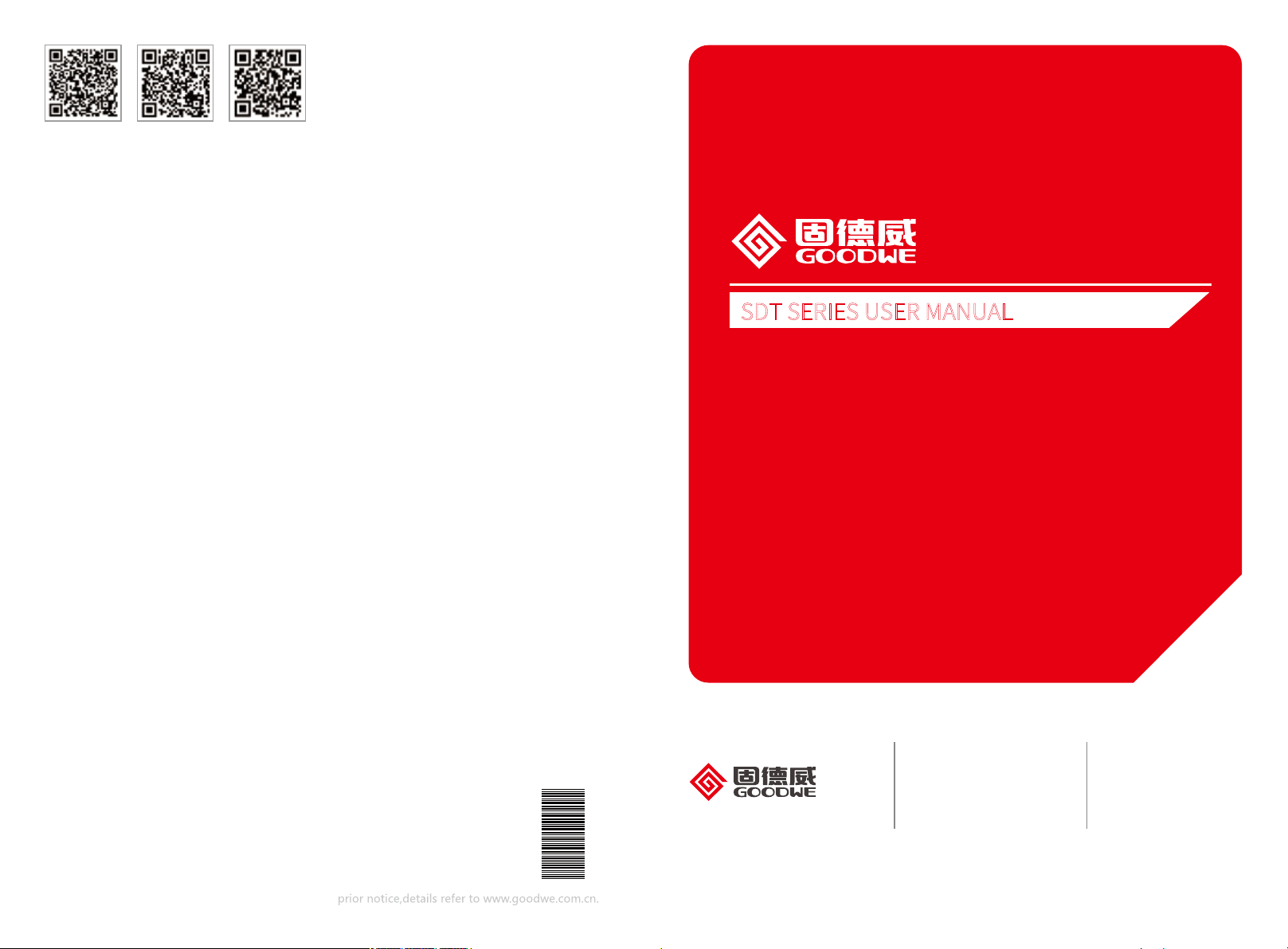
3.2 Inverter Overview and Package
Check the scope of delivery for completeness and any visible damage.
3.2.1 Inverter Overview
SDT4~6KW Refer to Figure3.2.1-1,SDT8~15KW Refer to Figure3.2.1-2.
SDT4~6KW
1. PV input terminals
2. DC Switch (Optional)
METER
DRED
6
Figure 3.2.1-1
3. Com Model
4. AC output terminal
5. Indicator lights
6. Button
0201
SDT8~15KW
Max
6
7
1. PV input terminals
(SDT12~15KW PV *3pair)
2. DC Switch (Optional)
3. Com Model
4. AC output terminal
5. Fan
6. Indicator lights
7. Button
Figure 3.2.1-2
3.2.2 Package
Inverter *1
AllenWrench *1
(VACONN AC PLUG Only)
Wi-Fi
Connection
Guide
Wi-Fi Connection
Guide *1
(WiFi Model Only)
Wall-mounted
Bracket *1
PE Terminal *1
Com Model
DC Plug *2pair AC Connector Screw*6
Expansion Bolts *6
APP
User Manual *1
Quick Installation
Guide *1
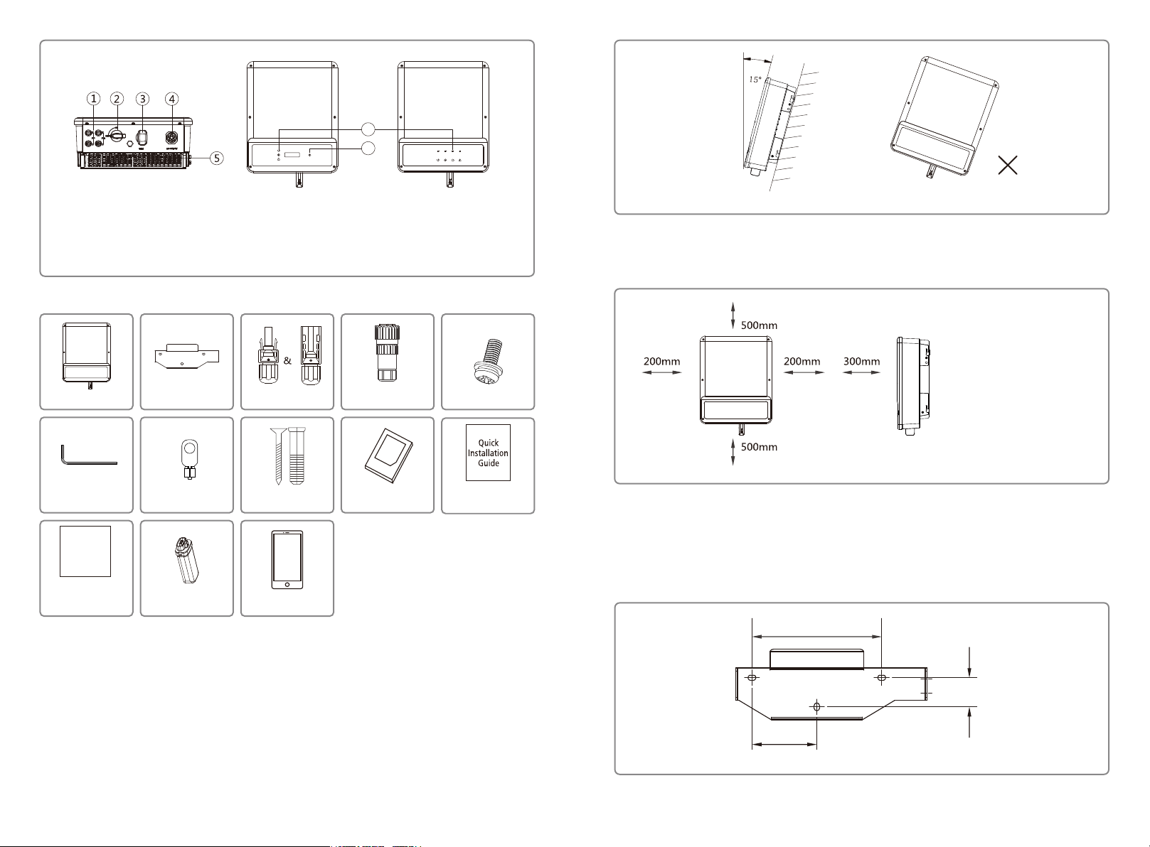
3.3 Inverter Installation
3.3.1 Selecting the installation location
The following must be considered when selecting the best location for an inverter:
• The mount and installation method must be appropriate for the inverter’s weight and
dimensions.
• The location must be well ventilated and sheltered from direct sunlight.
• The inverter must be installed vertical or with a backward tilt less than 15.No sideways tilt is
allowed. The connection area must point downwards. Refer to Figure 3.3.1-1.
Figure 3.3.1-1
To allow dissipation of heat, and for convenience of dismantling, clearnaces around the
inverter must be at least:
The installation position shall not prevent access to the disconnection means.
Upward
Downward
Front
Both sides
-------------500mm
---------500mm
----------------300mm
----------200mm
Figure 3.3.1-2
3.3.2 Mounting Procedure
(1) Use the wall-mounted bracket as a template and drill holes in the wall, 10 mm in diameter
and 80mm deep. SDT referred Figure 3.3.2-1.
(2) Fix the wall mounting bracket on the wall using the expansion bolts in the accessories bag.
(3) Hold the inverter by the side groove as Figure 3.3.2-2.
(4) Install the inverter on the wall-mounted bracket. SDT referred to Figure 3.3.2-3.
200mm
45mm
100mm
Figure 3.3.2-1
0403
 Loading...