

GOODWE HYBRID INVERTER User Manual
PV Master APP SEMS Portal APP SEMS Portal website
www.semsportal.com
LinkedIn Company's
offical website
JIANGSU GOODWE POWER SUPPLY TECHNOLOGY CO.,LTD
No. 90 Zijin Rd., New District, Suzhou, 215011, China
www.goodwe.com
service@goodwe.com
BH SERIES USER MANUAL
HYBRID INVERTER
340-00310-01

TABLE OF CONTENTS
01 INTRODUCTION
1.1 Operation Modes Introduction ........................................................................................ 01
1.2 Safety & Warning ................................................................................................................ 02
1.3 Product Overview .............................................................................................................. 04
02 INSTALLATION INSTRUCTIONS
2.1 Unacceptable Installations ............................................................................................... 05
2.2 Packing List ......................................................................................................................... 05
2.3 Mounting ............................................................................................................................. 06
2.3.1 Select Mounting Location ....................................................................................... 06
2.3.2 Mounting .................................................................................................................... 07
2.4 Electrical Wiring Connection ............................................................................................ 09
2.4.1 Battery Wiring Connection ...................................................................................... 09
2.4.2 On-Grid & Back-Up Connection ............................................................................. 10
2.4.3 Smart Meter & CT Connection ................................................................................ 13
2.5 DRED / Remote Shutdown Connection .......................................................................... 15
2.6 Earth Fault Alarm Connection .......................................................................................... 16
03 MANUAL OPERATION
3.1 Wi-Fi Configuration ............................................................................................................. 19
3.2 PV Master App ...................................................................................................................... 20
3.3 CEI Auto-Test Function ....................................................................................................... 20
04 OTHERS
4.1 Error Messages ................................................................................................................... 21
4.2 Troubleshootings ............................................................................................................... 23
4.3 Disclaimer ........................................................................................................................... 27
4.4 Technical Parameters ........................................................................................................ 28
4.5 Other Test ............................................................................................................................ 29
4.6 Quick Check List To Avoid Danger ................................................................................... 30
01 INTRODUCTION
GoodWe BH series bidirectional inverter is designed for both indoor and outdoor use, which could
be used with or without existing grid-tied inverter systems to store energy using batteries.
Energy produced from the grid-tied inverters will be used to optimize self-consumption, excess
will be used to charge the battery, anymore could be exported to the grid. Loads will be supported
in priority by grid-tied system, then battery power, if more power is needed, energy will be imported from the grid.
Note:
The introduction describes a general behavior of BH system. The
operation mode can be adjusted on PV Master App depending
on the system layout. Below are the general operation modes for
01
BH system:
1.2 Safety & Warning
The BH series inverter of Jiangsu GoodWe Power Supply Technology Co., Ltd. (hereinafter
called as GoodWe) strictly complies with related safety rules for product design and testing.
Please read and follow all the instructions and cautions on the inverter or user manual during
installation, operation or maintenance, as any improper operation might cause personal or
property damage.
Symbols Explantion
Caution!
Failure to observe a warning indicated in this manual may result in injury
Danger of high voltage and electric shock!
Danger of hot surface!
02
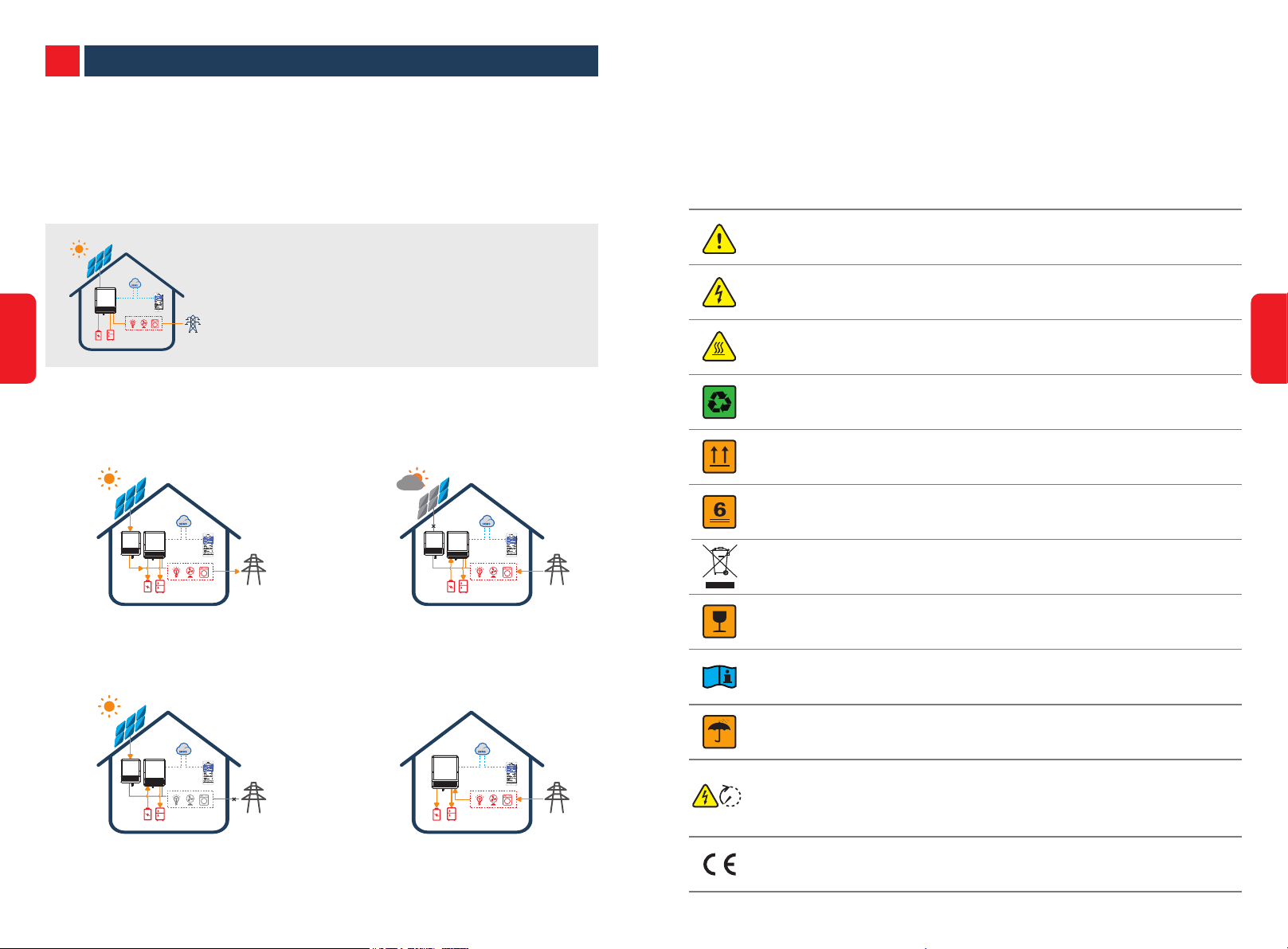
1.1 Operation Modes Introduction
BH system normally has the following operation modes based on your configuration and layout
conditions.
Mode Ⅰ
Energy from grid-tied inverters optimize loads, excess will
be used to charge the battery, anymore will be exported to
the grid.
Mode Ⅲ
When grid power fails, battery will discharge to support
back-up loads.
Mode Ⅱ
When energy from grid-tied inverters is weak, battery will
discharge to support the load in priority together with the
grid.
Mode Ⅳ
Battery could be charged by grid, and charge time/power
could be set flexibly on PV Master App.
Components of the product can be recycled.
This side up! The package must always be transported, handled and stored in
such a way as the arrows always point upwards.
No more than six (6) identical packages being stacked on each other.
Products should not be disposed as household waste.
Fragile - The package/product should be handled carefully and never be
tipped over or slung.
Refer to the operating instructions.
Keep dry! The package/product must be protected from excessive humidity and
must be stored under cover.
Signals danger due to electric shock and indicates the time to wait (5 minutes)
before it is safe to touch the internal parts of the inverter after it has been
5min
disconnected from it power source
CE Mark

Safety Warning
Any installation and operation on inverter must be performed by qualified electricians, in
compliance with standards, wiring rules or requirements of local grid authorities or companies
(like AS 4777 and AS/NZS 3000 in Australia).
Prohibit to insert or pull the AC and DC terminals when the inverter is running.
Before any wiring connection or electrical operation on inverter, all battery and AC power
must be disconnected from inverter for at least 5 minutes to make sure inverter is totally
isolated to avoid electric shock.
The temperature of inverter surface might exceed 60℃ during working, so please make sure
it is cooled down before touching it, and make sure the inverter is untouchable for children
1.3 PRODUCT OVERVIEW
FAULT
BLINK1 = OVERLOAD OF BACK-UP
OFF = NO FAULT
OUTPUT / REDUCE LOAD
WiFi
BLINK 1 = WiFi SYSTEM RESETTING
BLINK 2 =
BLINK4 = WIFI SERVER PROBLEM
OFF = WIFI NOT ACTIVE
ON = FAULT HAS OCCURRED
WiFi NOT CONNECT TO ROUTER
BLINK2 =
OFF =
ON = WiFi CONNECTED / ACTIVE
BMS AND METER COMMUNICATION FAIL
COMMUNICATION FAIL
METER COMMUNICATION OK, BMS
COM
BLINK1 =
COMMUNICATION FAIL
METER COMMUNICATION OK, BMS
ENERGY
OFF =
ON = CONSUMING ENERGY FROM GRID / BUYING
BLINK 1 =
BLINK 2 =
ON =
BMS AND METER COMMUNICATION OK
GRID IS NOT CONNECTED OR SYSTEM NOT
OPERATING
SUPPLYING ENERGY TO GRID / ZEROING
SUPPLYING ENERGY TO GRID / ZEROING
GRID
BLINK 1 = BATTERY IS DISCHARGING
BLINK 2 = BATTERY IS LOW / SOC IS LOW
BATTERY
OFF = BACK-UP IS OFF / ON POWER AVAILABLE
ON = BATTERY IS CHARGING
BLINK1 = BATTERY IS DISCHARGING
BLINK2 = BATTERY IS LOW / SOC IS LOW
OFF =
ON = GRID IS ACTIVE AND CONNECTED
BATTERY IS DISCONNECTED / NOT ACTIVE
INDICATOR
BACK-UP
SYSTEM
ON = SYSTEM IS READY
BLINK = SYSTEM IS STARTING UP
OFF = SYSTEM IS NOT OPERATING
ON = BACK-UP IS READY / POWER AVAILABLE
SYSTEM BACK-UP BATTERY GRID ENERGY COM WiFi FAULT
STATUS EXPLANATION
HYBIRD LED INDICATORS
03
Do not open inverter cover or change any components without GoodWe's authorization,
otherwise the warranty commitment for the inverter will be invalid.
Usage and operation of the inverter must follow instructions in this user manual, otherwise
the protection design might be useless and warranty for the inverter will be invalid.
Appropriate methods must be adopted to protect inverter from static damage. Any damage
caused by static is not warranted by GoodWe.
The inverter, with built-in RCMU, will exclude possibility of DC residual current to 6mA, thus
in the system an external RCD (type A) can be used(≥30mA).
In Australia, the inverter internal switching does not maintain neutral integrity, which must
be addressed by external connection arrangements like in the system connection diagram
for Australia on page 16.
In Australia, output of Back-Up side in switchbox should be labeled "Main switch UPS
supply", the output of normal load side in switch box should be labeled "main switch inverter supply".
Battery terminals
Wi-Fi box
To battery
Smart meter communication cable
BMS communication cable
DRED
To Smart Meter
RS485
Reserved
Back-Up Port
Meter
On-Grid port
04
Wi-Fi reset
LED label
02 INTALLATION INSTRUCTIONS
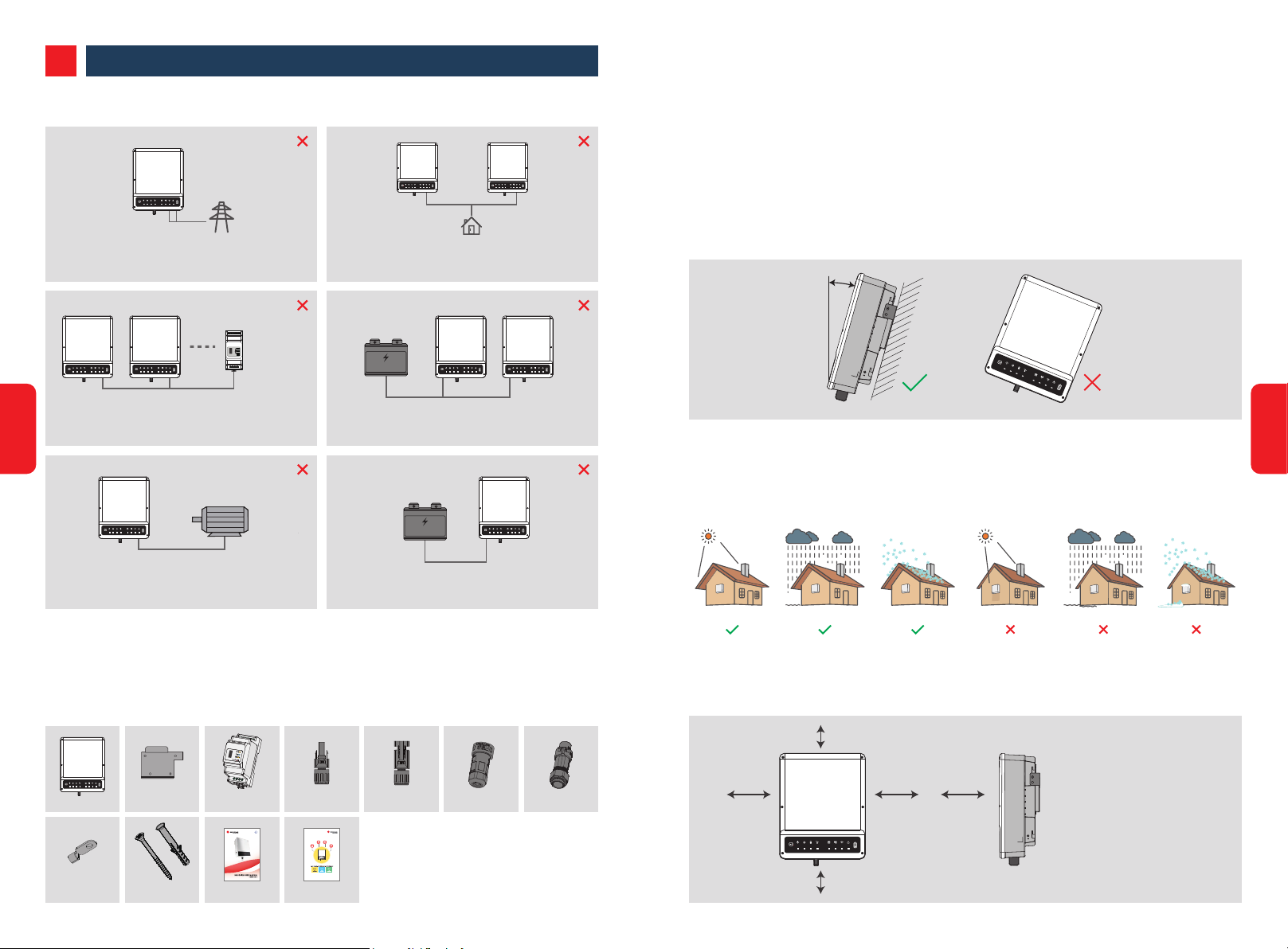
2.1 UNACCEPTABLE INSTALLATIONS
Wi-Fi
SYSTEM BACK-UP BATTERY GRID ENERGY COM WIFI FAULT
RESET
Back-Up
On-Grid
SMART METER
USB
Wi-Fi
SYSTEM BACK-UP BATTERY GRID ENERGY COM WIFI FAULT
RESET
Wi-Fi
SYSTEM BACK-UP BATTERY GRID ENERGY COM WIFI FAULT
RESET
Back-Up Back-Up
One meter cannot connect to multi inverters, and different
05
CT cannot connect to a smart fier cable
Wi-Fi
SYSTEM BACK-UP BATTERY GRID ENERGY COM WIFI FAULT
RESET
Back-Up
On-Grid
On-Grid or back-up side cannot connect to any ac
generator.
Reset
Generator
Smart Meter
Wi-Fi
SYSTEM BACK-UP BATTERY GRID ENERGY COM WIFI FAU LT
RESET
Wi-Fi
SYSTEM BACK-UP BATTERY GRID ENERGY COM WIFI FAU LT
RESET
Back-Up Back-Up
Load
Back-up cannot connect in parallelBack-up cannot connect to grid
Incompatible batter y
Battery
Wi-Fi
SYSTEM BACK-UP BATTERY GRID ENERGY COM WIFI FAULT
RESET
Wi-Fi
SYSTEM BACK-UP BATTERY GRID ENERGY COM WIFI FAULT
RESET
Battery Battery
One battery bank cannot be connected to multi inverters
Incompatible batter y
Wi-Fi
SYSTEM BACK-UP BATTERY GRID ENERGY COM WIFI FAULT
Battery
RESET
Battery
Inverter battery input cannot connect to incompatible
batteries.
2.3 Mounting
2.3.1 Select Mounting Location
For inverter's protection and convenient maintenance, mounting location for inverter should be
selected carefully based on the following rules:
Any part of this system shouldn't block the switch and breaker to disconnected inverter from DC
and AC power.
Rule 1. Inverter should be installed on a solid surface, where is suitable for inverter's dimensions
and weight.
Rule 2. Inverter installation should stand vertically or lie on a slop by max 15°
Max
15°
Wi-Fi
RESET
SYSTEM
BACK-UP
BATTERY
GRID
ENERGY
COM
WIFI
FAULT
Rule 3. Ambient temperature should be lower than 45°C
(High ambient temperature will cause power derating of inverter)
Rule 4. The installation of inverter should be protected under shelter from direct sunlight or bad
Rule weather like snow, rain, lightning etc.
Keep away from sunlight Keep dry Keep it clear of snow Sun Rain Accmulated snow
06
2.2 Packing List
On receiving the BH series inverter, please check to make sure all the components as below are not
missing or broken.
USB
Wi-Fi
SYSTEM BACK-UP BATTERY GRID ENERGY COM WIFI FAULT
RESET
Inverter×1
Inverter Smart Meter Positive BAT Plug Negative BAT Plug Back Up AC Plug On Grid AC Plug
PE terminal Expansion bolts User manual Quick Installation Guide
Wall-mounted
Bracket
Rule 5. Inverter should be installed at eye level for convenient maintenance.
Rule 6. Product label on inverter should be clearly visible after installation.
Rule 7. Leave enough space around inverter following the values.
300mm
Upward
200mm 200mm
300mm
---------- 300mm
Downward
Front
------------- 300mm
Both sides
Wi-Fi
SYSTEM BACK-UP BATTERY GRID ENERGY COM WIFI FAULT
RESET
500mm
------ 500mm
-------- 200mm
Inverter cannot be installed near flammable, explosive or strong electro-magnetic
equipment.[1]
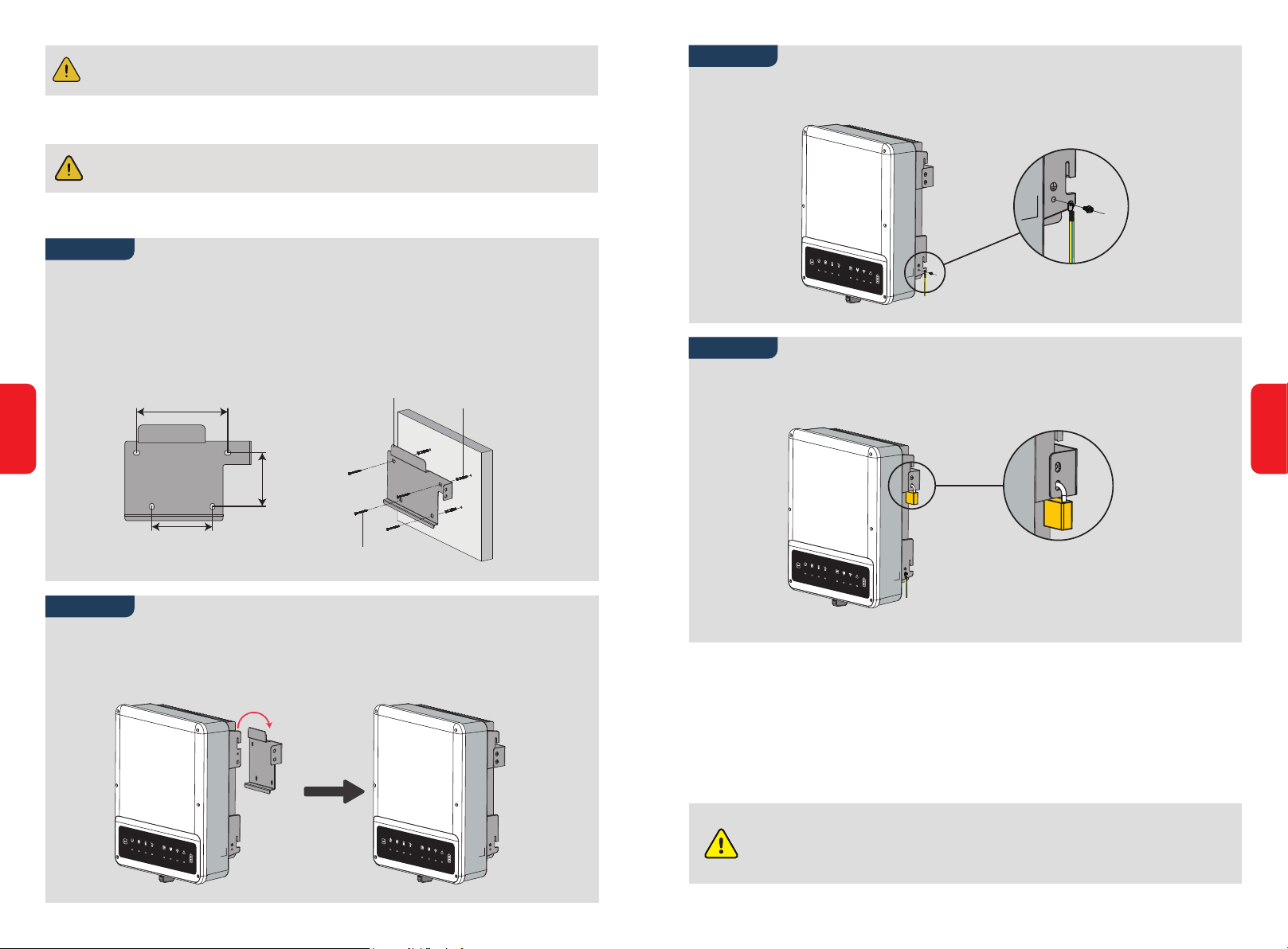
2.3.2 MOUNTING
Inverter cannot be installed near flammable, explosive or strong electro-magnetic
equipment.[1]
The inverter is suitable for mounting on concrete or other non-combustible surface only.
Step 3
Ground cable must be connected to ground plate on grid side.
07
Step 1
• Please use the mounting bracket as a template to drill 4 holes on right positions (10mm
in diameter,and 80mm in depth)
• Use expansion bolts in accessory box and fix the mounting bracket onto the wall tightly
Note: Bearing capacity of the wall must be higher than 25kg, otherwise may not be able to
keep inverter from dropping.
Wall bracket
195mm
115mm
130mm
self-tapping screws
Expansion pipe
Step 2
Carry the inverter by holding the heating sink on two sides and place the inverter on the
mounting bracket.
Note: Make sure the heat sink on inverter is right joint with mounting bracket.
Wi-Fi
RESET
SYSTEM
BACK-UP
BATTERY
GRID
ENERGY
COM
WIFI
FAULT
Step 4
A lock could be used for anti-theft if it is necessary for individual requirement.
Wi-Fi
RESET
SYSTEM
BACK-UP
BATTERY
GRID
ENERGY
COM
WIFI
FAULT
The lock is not involved in the package,
It can be purchesed by user.
2.4 Electrical Wiring Connection
2.4.1 Battery Wiring Connection
• Please be careful against any electric shock or chemical hazard.
• Make sure there is an external DC breaker (≥40A) connected for battery without build-in DC
breaker.
08
Make sure battery breaker is off and battery nominal voltage meet BH specification
Wi-Fi
RESET
SYSTEM
BACK-UP
BATTERY
GRID
ENERGY
COM
WIFI
FAULT
Wi-Fi
RESET
SYSTEM
BACK-UP
BATTERY
GRID
ENERGY
COM
WIFI
FAULT
before connecting battery to inverter and make sure inverter is totally isolated from
AC power.
 Loading...