

Goodwe GW3600-NS, GW1000-NS, GW3000-NS, GW3000D-NS, GW2000-NS User Manual
...
340 -0000 7-05
Official Website
Company Wechat
GoodWe(China)
No.189 Kunlunshan Rd.,SND,
Suzhou,215163,China
T: 400 998 1212
service.chn@goodwe.com.cn
www.goodwe.com.cn
www.goodwe.com.cn
service.au@goodwe.com.cn
GoodWe(Australia)
www.goodwe.com.cn
service.nl@goodwe.com.cn
GoodWe(Netherlands) GoodWe(UK)
www.goodwe.co.uk
enquiries@goodwe.co.uk
Note: The information above is subject to change without prior notice,details refer to www.goodwe.com.cn.
SOLAR INVERTER
NS/DNS SERIES USER MANUAL

1 Symbols
2 Safety
3 Installation
4 System Operation
5 Troubleshooting
6 Technical Parameters
7 Certificates
8 Maintenance
3.1 Mounting Instructions
3.2 Inverter Overview and Package
3.3 Inverter Installation
3.4 Electrical Connection
4.1 Indicator Lights
4.2 User Interface and Use of the Display
4.3 Error Code
4.4 WiFi Reset and Reload to Factory Setting
4.5 Special Adjustable Setpoints
............................................................................................................ 01
............................ 02
................ 02
.............................. 03
............................... 05
.................................... 13
......... 13
............................................... 16
......................... 17
........................................................................................................ 01
.................................................................... 17
.................................................... 18
.................................................................................. 22
.................... 17
.................................................................................. 22
If th ere are m ore tha n 3 PV stri ngs on in put sid e, an addit ional f use ins talli ng will b e sugge sted.
An ea rthin g photo volta ic syst em need t o conne ct an Arc fau lt dete ctor on D C side.
The in verte r can exc lude th e possi bilit y of DC res idual c urren ts to 6mA i n the sys tem,W here an e xtern al RCD is r equir ed
in ad ditio n to the bu ilt-i n RCMU, typ e A RCD mu st be use d to avoi d tripp ing。
The PV- i s not gro unded a s defau lt conf igura tion.
CE Mark
Signals danger due to electrical shock and indicates the time (5minutes) to allow after the
inverter has been turned off and disconnected to ensure safety in any installation operation.
Caution! - Failure to observe a warning
indicated in this manual may result in minor
or moderate injury.
Danger of high voltage and electric shock!
Danger of hot surface!
Product should not be disposed as normal
household waste.
Components of the product can be recycled.
This side up - The package must always be
transported, handled and stored in such a
way that the arrows always point upwards.
No more than six (6) identical packages be
stacked on each other.
The package/product should be handled
carefully and never be tipped over or
slung.
Keep Dry – The package/product must be
protected from excessive humidity and
must accordingly be stored under cover.
1 Symbols
2 Safety
The NS /DNS se ries in verte r of Jian gsu Goo dWe Powe r Suppl y Techn ology C o, Ltd. (her einaf ter ref erred t o as Good We) str ictly
con forms t o relat ed safe ty rule s in desi gn and te st. Safe ty regu latio ns rele vant to th e locat ion sha ll be fol lowed d uring
ins talla tion,
com missi oning , ope ratio n and mai ntena nce. Impr oper op erati on may ha ve a risk o f elect ric sho ck or dam age to eq uipme nt
and p roper ty. (NS: Sin gle-M PPT,Sing le-Ph ase; DNS : Dual- MPPT,Sin gle-P hase)
Ins talla tion, ma inten ance an d conne ction o f inver ters mu st be per forme d by qual ified p erson nel, in co mplia nce wit h local
ele ctric al stan dards, re gulat ions an d the req uirem ents of l ocal po wer aut horit ies and /or com panie s.
To avoi d elect ric sho ck, DC inp ut and AC ou tput of t he inve rter mu st be dis conne cted an d wait at le ast 5 min utes be fore
per formi ng any in stall ation o r maint enanc e.
The te mpera ture of s ome par ts of the i nvert er may ex ceed 60℃ d uring o perat ion. To avoid b eing bu rnt, do no t touch t he
inv erter d uring o perat ion. Let i t cool be fore to uchin g it.
Keep c hildr en away f rom inv erter.
Do no t open th e front c over of t he inve rter. Apart f rom per formi ng work a t the wir ing ter minal ( as inst ructe d in this m anual ),
tou ching o r chang ing com ponen ts with out aut horiz ation m ay caus e injur y to peop le, damag e to inve rters a nd annu lment o f
the wa rrant y.
Sta tic ele ctric ity may d amage e lectr onic co mpone nts. Appro priat e metho d must be a dopte d to prev ent suc h damag e to the
inv erter ; oth erwis e the inv erter m ay be dam aged an d the warr anty an nulle d.
Ensu re the out put volta ge of the pr oposed PV a rray is lov er than th e maximu m rated inp ut volta ge of the inv erter; ot herwis e
the in verter m ay be damag ed and the wa rranty an nulled .
When e xposed t o sunligh t, the PV arr ay genera tes dang erous hi gh DC volta ge. Please o perate ac cordin g to our inst ructio ns,
or it wi ll result i n danger t o life.
PV mod ules sho uld have an I EC6173 0 class A rati ng.
If the e quipme nt is used in a ma nner not s pecifi ed by the man ufactu rer, the prote ction pr ovided by t he equip ment may be
impa ired.
Comp letely i solate t he equipm ent shou ld: switc h off the DC sw itch, disc onnect t he DC term inal, and di sconne ct the AC
term inal or AC brea ker.
Proh ibit ins erting o r pulling t he AC and DC term inals wh en the inve rter is el ectrif ied.
3 Installation
3.1 Mounting Instruction
In ord er to achie ve optim al perfor mance, the a mbient t empera ture shou ld be lowe r than 45℃.
For the c onvenie nce of che cking th e LCD displ ay and poss ible mai ntenan ce activ ities, ple ase insta ll the inv erter at ey e level.
Inve rters sh ould NOT be in stalle d near infl ammabl e and explo sive ite ms. Any st rong elec tro-ma gnetic e quipme nt shoul d be
kept awa y from ins tallat ion site.
Prod uct labe l and warni ng symbol s hall be cl ear to read a fter inst allati on.
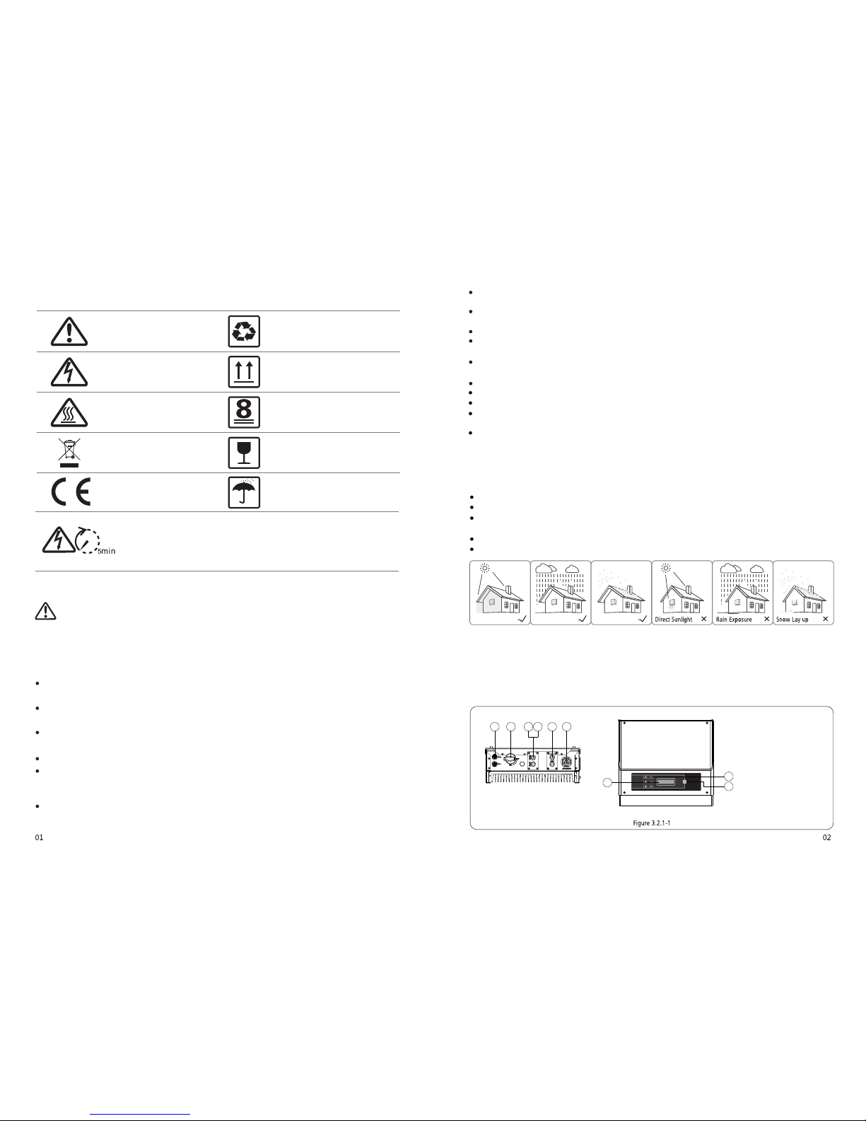
Plea se insta ll invert er in the pl ace where i s not expos ed to dire ct sunli ght, rain an d snow.
3.2 Inverter Overview and Package
Che ck the sc ope of de liver y for com plete ness an d any vis ible da mage.
3.2.1 Inverter Overview
Appearance of NS Series 1-3KW refer to Figure3.2.1-1. Appearance of NS Series 3.6-5KW and DNS Series 3-5KW refer to Figure3.2.1-2.
213 4 5 6
7
8
9
1. PV input terminals
2. DC Switch (Optional)
3. RS485 port or USB port
4. WiFi BOX (Optional)
S. CT and DRED function
(Optional)
6. AC output terminal
7. LCD display
8. Indicator lights
9. Button
.....
..
.
...
.
.
.......
..
.
.
..
.
..
...
213 4 5 6
7
8
9
1. PV input terminals
2. DC Switch (Optional)
3. RS-485 port or USB port
4. Wi-Fi antenna port (Optional)
5. CT and DRED function
(Optional)
6. AC output terminal
7. LCD display
8. Indicator lights
9. Button
3.2.2 Package
6Pin Terminalx1
2Pin Terminalx1
AC Plu gX1
DC PlugX2pair
Wall-mounted
Bracket x1
Inverterx1
Screwx4
Expansion Bolt sx5 Expansion Bolt sx5
Wi-Fi
Connection
Guide
Quick
Installati on
Guide
Quick Installa tion
Guidex1
Wi-Fi Connection
Guidex1
(WiFi BOM only)
There is 1 pair of DC connec tors in NS Series 1-3KW. and 2 pairs of DC conn ectors in NS Series 3.6-5 KW and DNS Series 3-5KW;
6Pin termi nal for RS485 functio n, 2Pin termi nal for CT function.
3.3 Inverter Installation
3.3.1 Selecting the installation location
The fol lowing m ust be cons idered w hen sele cting the b est loca tion for an i nverte r:
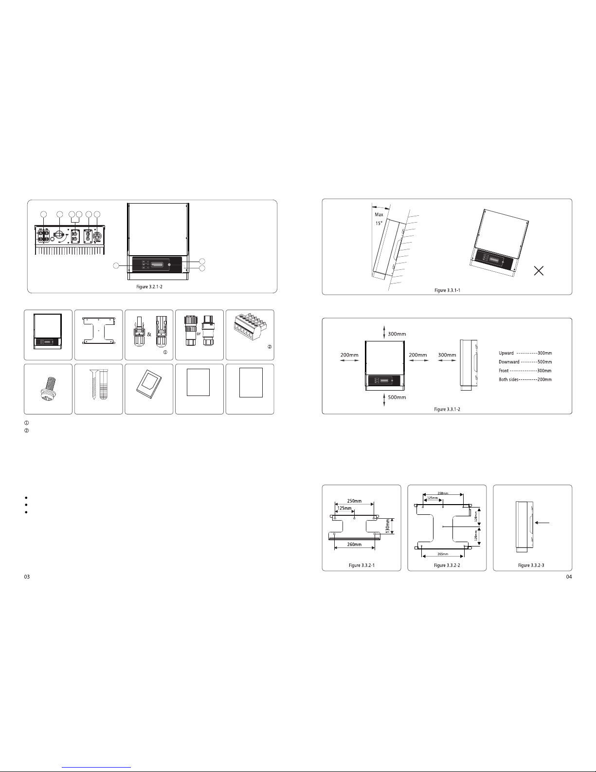
The mount a nd insta llatio n method mu st be appr opriat e for the inv erter' s weight an d dimens ions.
The locat ion must b e well vent ilated a nd shelt ered from d irect su nlight .
The inver ter must b e install ed verti cal or wit h a backwar d tilt less t han 15. No sid eways til t is allow ed. The connec tion
area m ust point d ownwar ds. Refer to Fig ure 3.3. 1-1.
To allow dissipat ion of heat, and for convenie nce of dismantling , clearanc es around the inverte r must be at least:
The installa tion position sha ll not prevent access to the di sconnection mea ns.
3.3.2 Mounting Procedure
(
refe rred to Figu re 3.3.2 -1, NS 3.6k W-5kW & DNS 3k W-5kW ref erred to Fi gure 3.3 .2-2.
(2) Fix t he wall mou nting bra cket on the wa ll using t he expans ion bolt s in the acce ssorie s bag.
(3) Ho ld the inve rter by th e side groo ve as Figur e 3.3.2-3 .
(4) In stall th e inverte r on the wall -mount ed bracke t. NS 1 kW~3kW r eferre d to Figure 3. 3.2-4, 3. 3.2-5. NS 3. 6kW-5kW & D NS
3kW-5 kW refer red to Figu re 3.3.2- 6, Figure 3. 3.2-7.
1) Use t he wall-m ounted b racket as a te mplate a nd drill ho les in the wa ll,10 mm in d iamete r and 80 mm dee p. NS 1 kW~ 3kW
 Loading...