

Goodwe GW3648D-ES, GW5048D-ES, EM Series User Manual
APP (iOS)Official Website APP (Android)
ES SERIES USER MANUAL
HYBRID INVERTER
No.189 Kun Lun Shan Road, SND, Jiangsu, China.
www.goodwe.com
service@goodwe.com
Jiangsu GoodWe Power Supply Technology Co.,Ltd
340-00004-03 Version: 1.0

INTRODUCTION
021.2 SAFETY & WARNINGS
041.3 PRODUCT OVERVIEW
011.1 OPERATION MODES INTRODUCTION
01
INSTALLATION INSTRUCTIONS
052.1 UNACCEPTABLE INSTALLATIONS
052.2 PACKING LIST
062.3 MOUNTING
062.3.1 SELECT MOUNTING LOCATION
072.3.2 MOUNTING
082.4 ELECTRICAL WIRING CONNECTION
082.4.1 PV CONNECTION
092.4.2 BATTERY CONNECTION
112.4.3 ON-GRID & BACK-UP CONNECTION
132.4.4 EZMETER & CT CONNECTION
142.5 DRED & EARTH FAULT ALARM
142.5.1 DRED CONNECTION
142.5.2 EARTH FAULT ALARM
02
MANUAL OPERATION
173.1 WIFI CONFIGURATION & WIFI RELOAD
183.2 PV MASTER APP OPERATION
183.3 CEI AUTO-TEST INSTRUCTION
03
OTHERS
194.1 ERROR MESSAGE AND TROUBLESHOOTING
254.2 DISCLAIMER
264.3 TECHNICAL PARAMETERS AND CERTIFICATES
284.4 WARINING QUICK CHECK LIST
04
TABLE OF CONTENTS
1.1 OPERATION MODES INTRODUCTION
The ES series inverters of Jiangsu GoodWe Power Supply Technology Co., Ltd. (hereinafter called as
GoodWe) strictly comply with related safety rules for product design and testing. Please read and
follow all the instructions and cautions on the inverter or user manual during installation, operation or
maintenance, as any improper operation might cause personal or property damage.
GoodWe ES series, also called hybrid or bidirectional solar inverters, apply to solar system with
participation of PV, battery, loads and grid system for energy management.
The energy produced by PV system shall be used to optimize self-consumption, excess power charge
battery and the rest power could be exported to the grid.
Battery shall discharge to support loads when PV power is insufficient to meet self-consumption. If
battery power is not sufficient, the system will take power from grid to support loads.
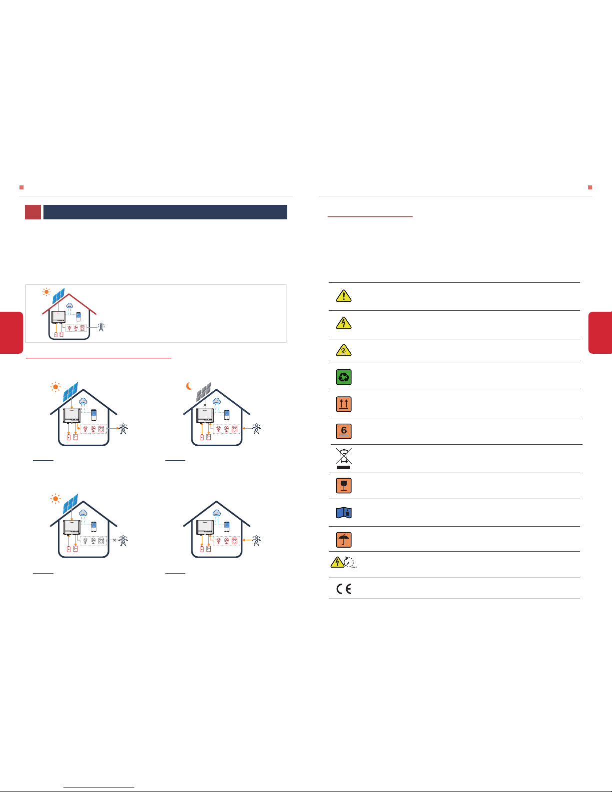
ES system normally has the following operation modes based on your configuration and layout conditions
1.2 SAFETY & WARNING
• SYMBOLS EXPLANATION
INTRODUCTION01
Caution!
Failing to observe a warning indicated in this manual may result in injury.
Danger of high voltage and electric shock!
Components of the product can be recycled.
This side up! The package must always be transported, handled and stored in such a
way that the arrows always point upwards.
Danger of hot surface!
No more than six (6) identical packages being stacked on each other.
Product should not be disposed as household waste.
The package/product should be handled carefully and never be tipped over or slung.
Refer to the operating instructions.
Keep dry! The package/product must be protected from excessive humidity and must
be stored under cover.
Inverter will be touchable or operable after minimum 5 minutes of being turned off or
totally disconnected, in case of any electrical shock or injury.
CE Mark
Note: the introduction describes a general behavior of ES
system. The operation mode can be adjusted on GoodWe
PV Master APP based on the system layout. Below are the
general operation modes for ES system:
The energy produced by the PV system is used to
optimize self-consumption. The excess energy is used to
recharge the batteries, then exported to grid.
Mode Ⅰ
When there is no PV, and the battery is sufficient , it can
supply the load together with grid power.
Mode Ⅱ
When grid fails , the system automatically switches to
Back-Up mode. The Back-Up load can be supported by
PV and battery.
Mode Ⅲ
Battery can be charged by grid, and charging
time/power can be set flexibly on PV Master APP.
Mode Ⅳ
02
INTRODUCTION INTRODUCTION
01
INTRODUCTION INTRODUCTION
• SAFETY WARNING
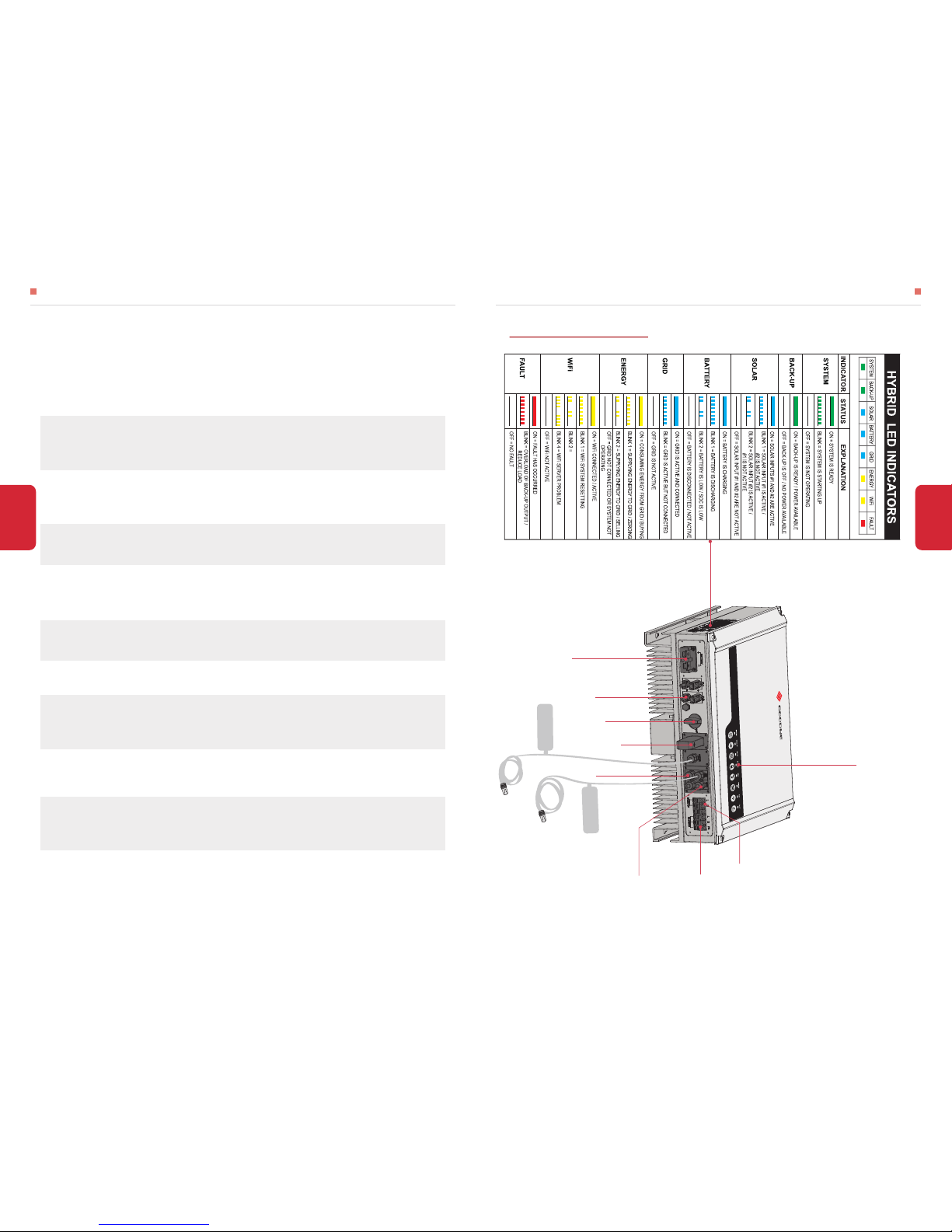
1.3 PRODUCT OVERVIEW
Any installation and operation on inverter must be performed by qualified electricians, in compliance
with standards, wiring rules or requirements of local grid authorities or companies (like AS 4777 and
AS/NZS 3000 in Australia).
Before any wiring connection or electrical operation on inverter, all DC and AC power must be
disconnected from inverter for at least 5 minutes to make sure inverter is totally isolated to
avoid electric shock.
The temperature of inverter surface might exceed 60℃ during working, so please make sure it
is cooled down before touching it, and make sure the inverter is untouchable for children.
Usage and operation of the inverter must follow instructions in this user manual, otherwise the
protection design might be useless and warranty for the inverter will be invalid.
PV negative (PV-) on inverter side is not grounded as default design.
The inverter, with built-in RCMU, will exclude possibility of DC residual current to 6mA, thus in
the system an external RCD (type A) can be used(≥30mA).
IN Australia, output of Back-Up side in switchbox should be labeled ‘Main Switch UPS supply’,
the output of normal load side in switch box should be labeled ‘Main Switch Inverter Supply’.
Do not open inverter cover or change any components without GoodWe’s authorization,
otherwise the warranty commitment for the inverter will be invalid.
Appropriate methods must be adopted to protect inverter from static damage. Any damage
caused by static is not warranted by GoodWe.
PV modules used on the inverter must have an IEC61730 class A rating, and the total
open-circuit voltage of PV string/array is lower than the maximum rated DC input voltage of the
inverter. Any damage caused by PV over-voltage is beyond warranty.
In Australia, the inverter internal switching does not maintain neutral integrity, which must be
addressed by external connection arrangements like in the Off-Grid System Connection
Diagram in page 16.
0403
WiFi NO T CONNE CT TO ROUT ER
PV Terminals
Battery Terminals
Reserved RS485
Back-Up Port
On-Grid Port
DC Switch
LED Lable
To Battery
To EzMeter
DRED
Wi-Fi Box
BMS Communication Cable
EzMeter Communication Cable
Battery
CANNOT CONNECT TO
INCOMPATIBLE BATTERIES
Incompatible battery
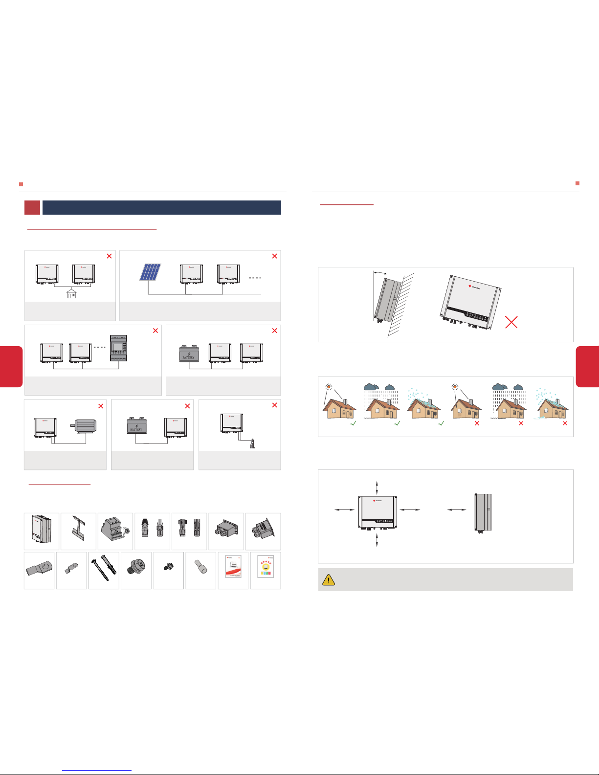
2.1 UNACCEPTABLE INSTALLATIONS
2.2 PACKING LIST
INSTALLATION INSTRUCTIONS INSTALLATION INSTRUCTIONS
05
06
Please avoid the following installations, which will damage the system or the inverter.
On receiving the inverter, please check to make sure all the components as below are not missing or
broken.
SINGLE PV STRING CANNOT CONNECT TO TWO OR MORE INVERTERS.
Back-Up On-Grid
Battery Battery
ONE EZMETER CANNOT CONNECT TO MULTI INVERTERS, AND
DIFFERENT CT CANNOT CONNECT TO A SAME FIER CABLE.
ONE BATTERY BANK CANNOT BE CONNECT TO
MULTI INVERTERS.
EzMeter
ON-GRID OR BACK-UP SIDE CANNOT
CONNECT TO ANY AC GENERATOR.
Generator
2.3.1 SELECT MOUNTING LOCATION
2.3 MOUNTING
Rule 1. Inverter should be installed on a solid surface, where is suitable for inverter’s dimensions and
weight.
Rule 2. Inverter installation should stand vertically or lie on a slop by max 15° (Pic 1)
Rule 3. Ambient temperature should be lower than 45℃
Rule 4. The installation of inverter should be protected under shelter from direct sunlight or bad
weather like snow, rain, lightning etc. (Pic 2)
Rule 5. Inverter should be installed at eye level for convenient maintenance.
Rule 6. Product label on inverter should be clearly visible after installation.
Rule 7. Leave enough space around inverter following the values on pic 3.
Direct Sunlight Exposure to Rain Exposure to SnowNo Direct Sunlight No Exposure to Rain No Exposure to Snow
Pic 2
Upward----------
Downward------
Front-------------
Both sides-------
300mm
500mm
300mm
200mm
300mm
300mm
200mm 200mm
500mm
Pic 3
Inverter cannot be installed near flammable, explosive or strong electro-magnetic
equipment.
[1]
Pic 1
For inverter’s protection and convenient maintenance, mounting location for inverter should be
selected carefully based on the following rules:
Max
15°
INSTALLATION INSTRUCTIONS02
Wall-mounted
Bracket×1Inverter×1 AC Cover×1Positive DC Plug×2
or
Negative DC Plug×2
or
Battery cover × 1EzMeter & CT × 1
User Manual×1Expansion Bolts×6
Hexagon head
screw × 2 Pan head screw × 6 Pin Terminal × 6PE terminal × 1Battery terminal × 2
Quick Installation
Guide×1
BACK-UP SIDE CANNOT CONNECT
TO GRID
Back-Up On-Grid
BACK-UP CANNOT CONNECT IN PARALLEL.
Load
Back-Up
Back-Up
PV PV
INSTALLATION INSTRUCTIONS INSTALLATION INSTRUCTIONS
07
08
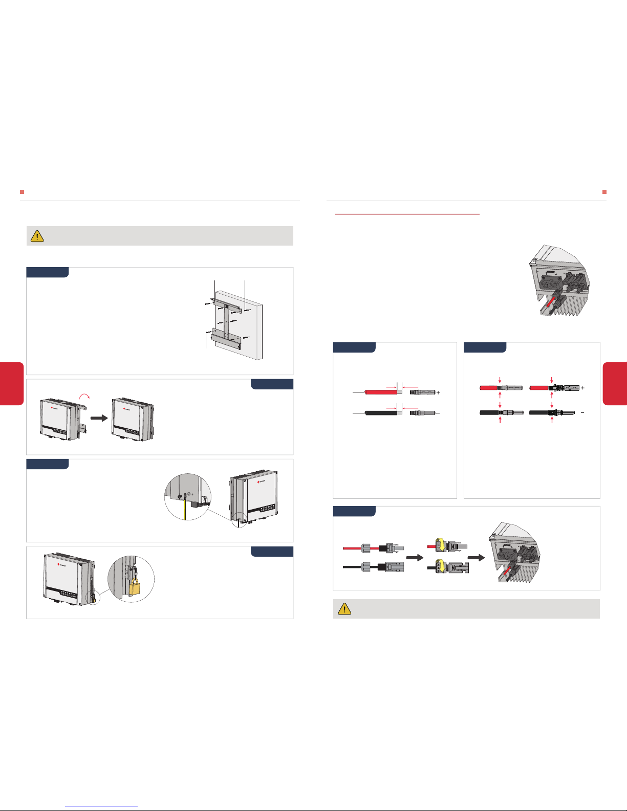
2.3.2 MOUNTING
Remember that this inverter is heavy! Please be careful when lifting out from the package.
[2]
The polarity of PV strings or on the inverter cannot be connected by reverse, otherwise
inverter could be damaged.
[3]
Step 2
Connect PV cable to DC connectors (Pic 9)
2.4.1 PV CONNECTION
Before connecting PV panels/strings to inverter, please make sure requirements are followed as below :
NOTE:There will be MC4 or Amphenol DC plugs in accessory box, the detailed connection as below:
• The minimum isolation resistance to ground of the PV string must
exceed 18.33kΩ in case of any shock hazard
• PV strings could not connect to earth/grounding conductor
• Use the DC plugs in the accessory box
• The total short-circuit current of PV string must not exceed
inverter’s max DC current
NOTE:
• Please use DC plugs and connectors in
GoodWe accessory box
• PV cable should be standard, 2.5-4mm
2
PV
cable
NOTE:
NOTE:
• PV cable must be tightly crimped into the
connectors
• For Amphenol connector, the limit buckle
cannot be pressed
• There will be a click sound if connectors are
inset correctly into DC plugs
• There will be a
click sound if
connectors are
inset correctly into
DC plugs
Prepare PV cables and DC plugs (Pic 8)
Screw the cap on and plug onto inverter side (Pic 10)
MC4 series
AMPHENOL series
2.5-4mm²
7mm
2.5-4mm²
7mm
Pic 8 Pic 9
2.4 ELECTRICAL WIRING CONNECTION
Pic 10
NOTE: Bearing capacity of the wall must be higher
than 30KG, otherwise may not be able to keep
inverter from dropping.
• Please use the mounting bracket as a template to
drill 6 holes on right positions (10mm in diameter,
and 80mm in depth) (Pic 4)
• Use expansion bolts in accessory box and fix the
mounting bracket onto the wall tightly
self-tapping
screws
Wall bracket Expansion pipe
Step 1
Pic 4
Step 2
Carry the inverter by holding the heating
sink on two sides and Place the inverter on
the mounting bracket. (Pic 5)
NOTE: Make sure the heat sink on inverter is
rightly joint with mounting bracket.
Pic 5
A lock could be used for anti-theft if it is
necessary for individual requirement.
(Pic 7)
Step 4
Pic 7
Step 3
Ground cable shall be connected to ground
plate on grid side (Pic 6)
Pic 6
Step 1 Step 2
Step 3
The inverter is suitable for mounting on concrete or other non-combustible surface only
 Loading...