

Goodwe GW1500-SS, GW2000-SS, GW4600-SS, GW3000-SS, GW4000-SS User Manual
...
User Manual
GOODWE SS SERIES
Ver 02
已发行
Table of Contents
1 Symbols . . . . . . . . . . . . . . . . . . . . . . . . . . . . . . . . . . 01
2 Safety . . . . . . . . . . . . . . . .. . . . . . . . . . . . . . . . . . . . . 02
3 Installation . . . . . . . . . . . . . . . . . . . . . . . . . . . . . . . . 04
3.1 Mounting Instructions . . . . . . . . . . . . . . . . . . . . . . 04
3.2 Unpacking . . . . . . . . . . . . . . . . . . . . . . . . . . . . . 04
3.3 Equipment Installation . . . . . . . . . . . . . . . . . . . . . 06
3.4 Electrical Connection . . . . . . . . . . . . . . . . . . . . . 10
3.5 Troubleshooting . . . . . . . . . . . . . . . . . . . . . . . . . . 32
4 System Operation . . . . . . . . . . . . . . . . . . . . . . . . . . . 35
4.1 Operating Panel . . . . . . . . .. . . . . . . . . . . . . . . . . . 35
4.2 Indicator Lights . . . . . . . . . . . . . . . . . . . . . . . . . . 35
4.3 LCD display . . . . . . . . . . . . . . . . . . . . . . . . . . . . 36
4.4 Error Messages . . . . . . . . . . .. . . . . . . . . . . . . . . . . 45
4.5 ID Reset . . . . . . . . . . . . . . . . . . .. . . . . . . . . . . . . 47
5 Technical Parameters . . . . . . . . . . . . . . . . . . . . . . . . 48
GW1500-SS GW2000-SS GW3000-SS . . . . . . . . . . . 48
GW4000-SS GW4600-SS . . . . . . . . . . . .. . . . . . . . . . . 51
GW3600S-UK/DK . . . . . . . . . . . . . . . . . . . . . . . . . . . 54
6 Certificates . . . . . . . . . . . . . . . . . . . . . . . . . . . . . . . . 57
7 Warranty . . . . . . . . . . . . . . . . . . . . . .. . . . . . . . . . . . 58
7.1 Warranty Period . . . . . . . . . . . . . . . . . . . . . . . . . . 58
7.2 Warranty Card . . . . . . . . . . . . . . . . . . . . . . . . . . 58
7.3 Warranty Conditions . . . . . . . . . . . . . . . . . . . . . . 58
7.4 Scope of Warranty . . . . . . . . . . . .. . . . . . . . . . . . . 59
8 Contact . . . . . . . . . . . . . . . . . . . . . . . . . . . . . . . . . . . 60
Notes:
The images and diagrams in this manual are for guidance
only. Please refer to the actual product.
已发行
1
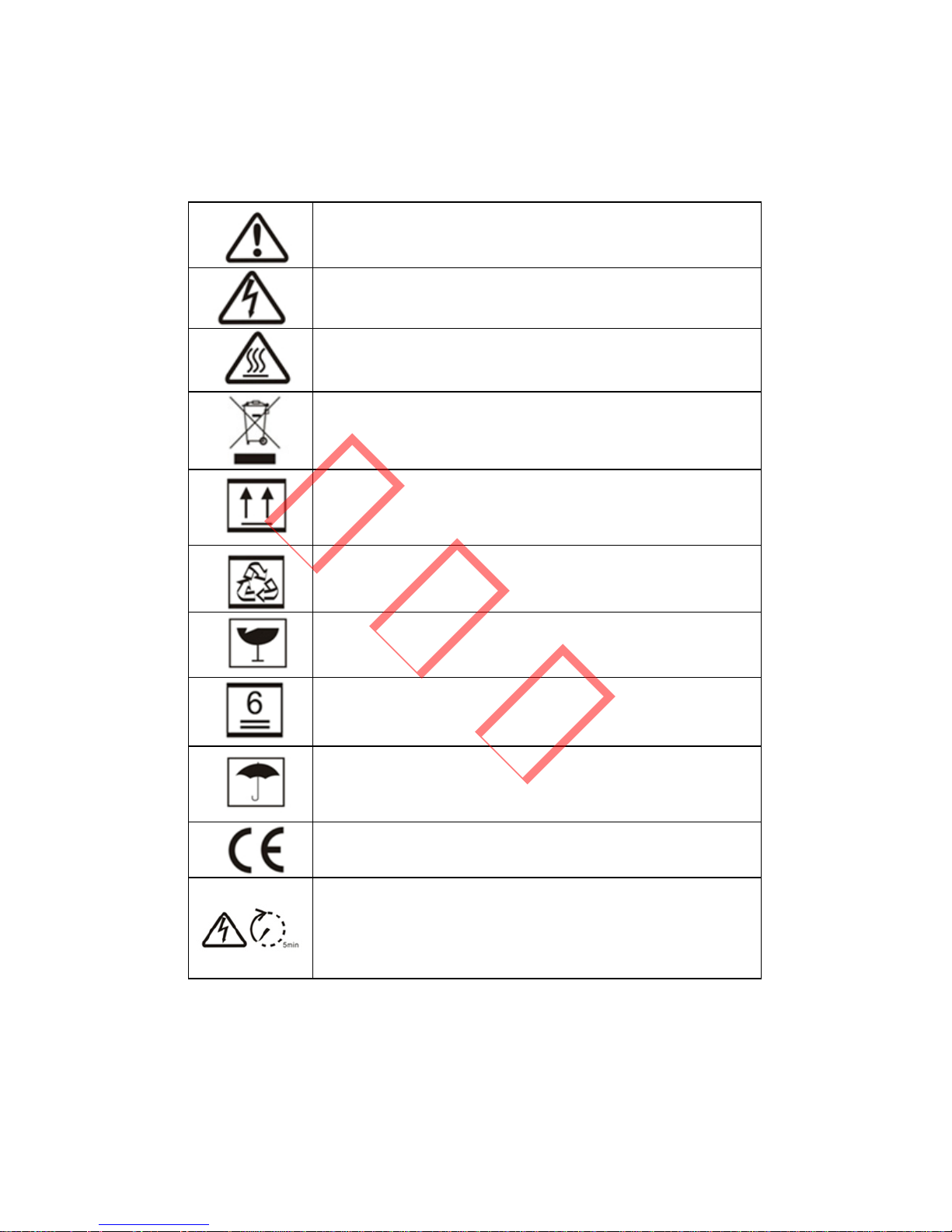
1 Symbols
Caution! - Failure to observe a warning
indicated in this manual may result injury.
Danger of high voltage and electric shock!
Danger of hot surface!
Product should not be disposed as household
waste.
This side up; the package must always be
transported, handled and stored in such a way
that the arrows always point upwards.
Components of the product can be recycled.
Fragile; the package/product should be handled
carefully and never be tipped over or slung.
No more than six (6) identical packages may be
stacked on each other.
Keep dry; the package/product must be
protected from excessive humidity and must be
stored under cover.
CE Mark
Residual voltage exists in the inverter; before
commencing any maintenance, at least 5
minutes must be allowed for the capacitor in the
inverter to fully discharge.
已发行
2
Units:
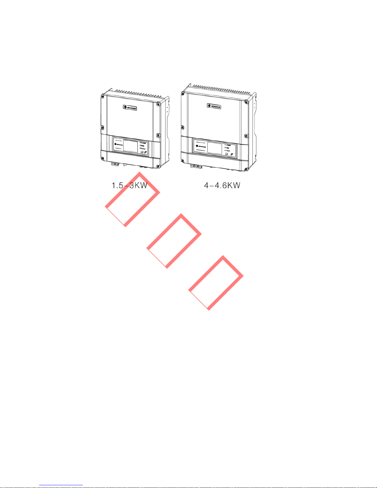
2 Safety
The SS series inverter of Jiangsu GoodWe Power Supply
Technology Co. Ltd. ( hereinafter referred to as GoodWe )
strictly conforms to related safety rules in design and test.
Safety regulations relevant to the location shall be followed
during installation, commissioning, operation and maintenance.
Improper operation may cause serious injury, electric shock
and/or damage to equipment and property.
` Installation, maintenance and connection of inverters must
be performed by qualified personnel, in compliance with
local electrical standards, regulations and the requirements
of local power authorities and/or companies.
` To avoid electric shock, DC input and AC output of the
inverter must be terminated at least 5 minutes before
performing any installation or maintenance.
已发行

3
` The temperature of some parts of the inverter may exceed
60Ԩ during operation. To avoid being burnt, do not touch
the inverter during operation. Let it cool before touching it.
` Ensure children are kept away from inverters.
` Do not open the front cover of the inverter. Apart from
performing work at the wiring terminal (as instructed in this
manual), touching or changing components without
authorization may cause injury to people, damage to
inverters and annulment of the warranty.
` Static electricity may damage electronic components.
Appropriate methods must be adopted to prevent such
damage to the inverter; otherwise the inverter may be
damaged and the warranty annulled.
` Ensure the output voltage of the proposed PV array is lower
than the maximum rated input voltage of the inverter,
otherwise the inverter may be damaged and the warranty
annulled.
已发行

4
3 Installation
3.1 Mounting Instruction
A For optimal performance, the inverter must be located
where the ambient temperature is less than 45 °C.
B For convenience in maintenance and in checking the LCD
display, install the inverter at eye level.
C Inverters should NOT be installed near flammable and/or
explosive items. Any electro-magnetic equipment should
be kept away from the installation site.
D The product label and warning symbol must be clearly
visible after installation.
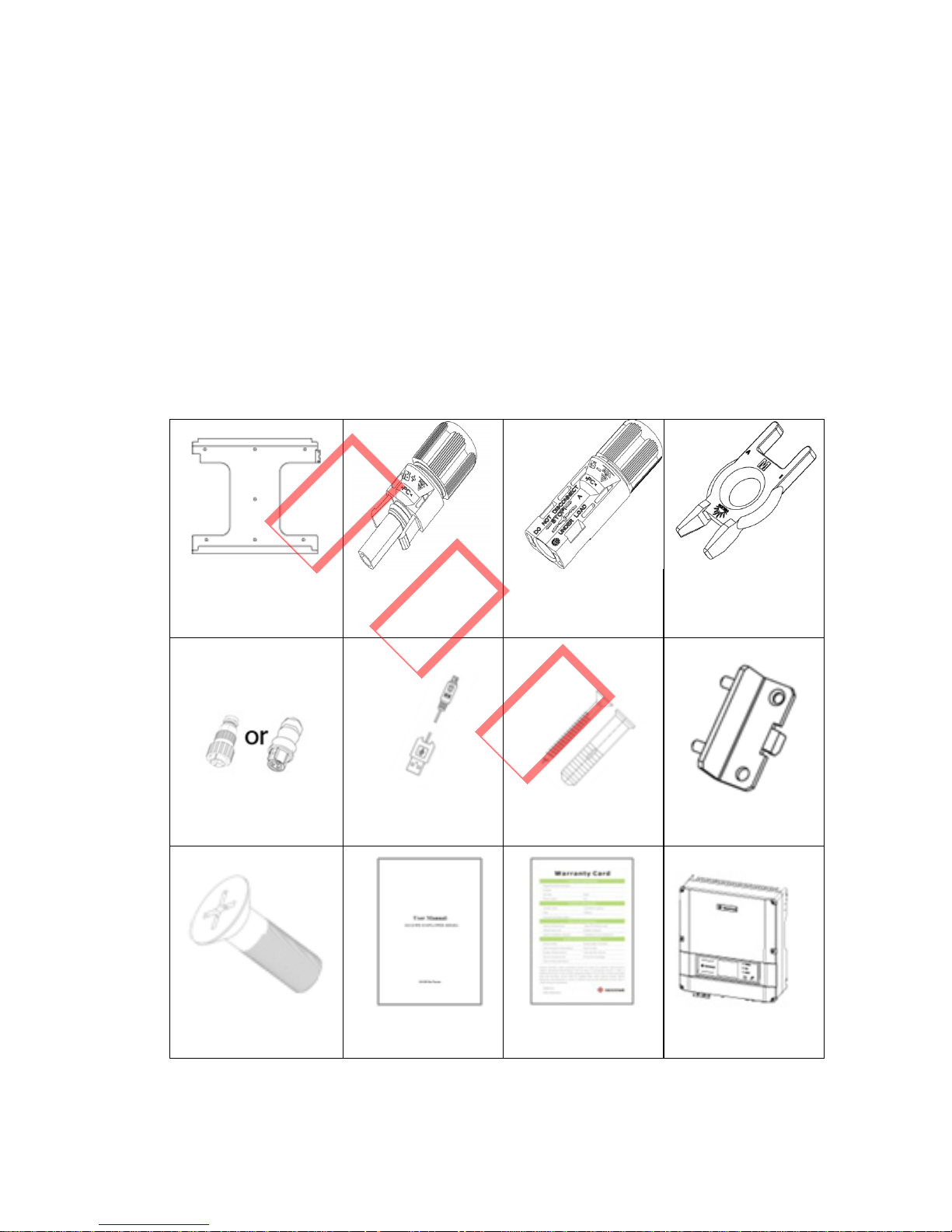
3.2 Unpacking
When you receive the GoodWe inverter, please check for
external damage to the inverter and any accessories. Please
also check that the following are included:
Inverter . . . . . . . . . . . . . . . . . . . . . . . . . . . . . . . . . . . . 1
Wall-mounted bracket . . . . . . . . . . . . . . . . . . . . . . . . . 1
Lock Plate . . . . . . . . . . . . . . . . . . . . . . . . . . . . . . . . . . 1
Positive DC Plug (GW1500-SS) . . . . . . . . . . . . . . . . . . 1
Negative DC Plug (GW1500-SS) . . . . . . . . . . . . . . . . . 1
Positive DC Plug (GW2000-SS / GW3000-SS) . . . . . . . 2
Negative DC Plug (GW2000-SS / GW3000-SS) . . . . . . 2
Positive DC Plug (GW3600S-UK/DK) . . . . . . . . . . . . . 3
Negative DC Plug (GW3600S-UK/DK) . . . . . . . . . . . . 3
Positive DC Plug (GW4000-SS / GW4600-SS) . . . . . . . 3
已发行
5
Negative DC Plug (GW4000-SS / GW4600-SS) . . . . . . 3
Unlock Tool for DC Plug . . . . . . . . . . . . . . . . . . . . . . . 1
AC Plug . . . . . . . . . . . . . . . . . . . . . . . . . . . . . . . . . . . 1
USB Data Cable . . . . . . . . . . . . . . . . . . . . . . . . . . . . . 1
Expansion Bolt . . . . . . . . . . . . . . . . . . . . . . . . . . . . . . 7
Flat Head Screw for Lock Plate and RS485 Cover . . . . . . 5
User Manual . . . . . . . . . . . . . . . . . . . . . . . . . . . . . . . . 1
Warranty Card . . . . . . . . . . . . . . . . . . . . . . . . . . . . . . . 1
Wall-mounted
Bracket
Positive DC Plug
Negative DC Plug
Unlock Tool for DC
Plug
AC Plug
USB Data Cable
Expansion Bolt
Lock Plate
Flat Head Screw
User Manual
Warranty Card
Inverter
已发行
6
3.3 Equipment Installation
3.3.1 Selecting the installation position
The following must be considered when selecting the best
location for an inverter:
` The mount and installation method must be suitable for the
inverter's weight and dimensions.
` The location must be well ventilated and sheltered from
direct sunlight.
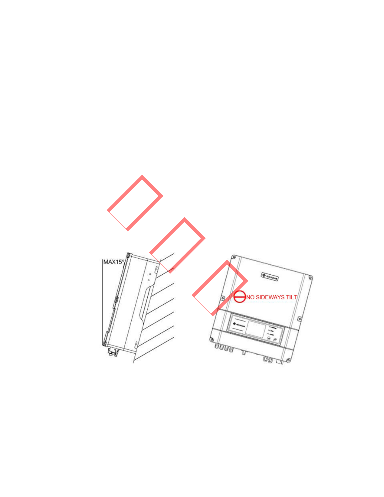
` Install vertically or tilted backward by max 15°. The device
cannot be installed with a sideways tilt. The connection area
must point downwards.
Figure 3.3.1-1
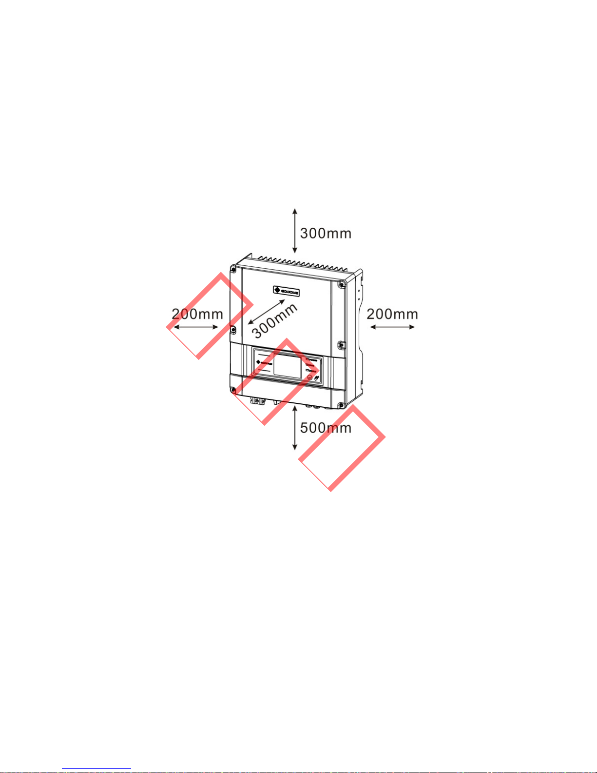
` To allow dissipation of heat, and for convenience of
dismantling, clearances around the inverter must be at least:
已发行
7
Upward . . . . . . . . . . . . . . . . . . . . . . . . . . . . . . . 300mm
Downward . . . . . . . . . . . . . . . . . . . . . . . . . . . . 500mm
Front . . . . . . . . . . . . . . . . . . . . . . . . . . . . . . . . 300mm
Both sides . . . . . . . . . . . . . . . . . . . . . . . . . . . . . 200mm
Figure 3.3.1-2
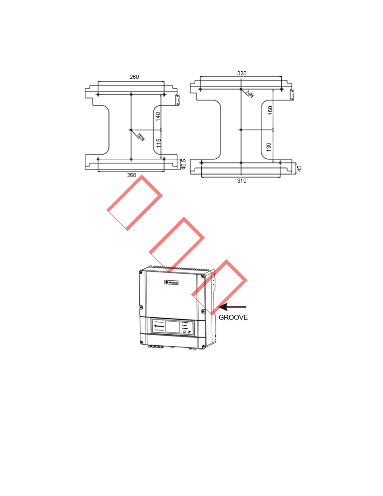
3.3.2 Mounting Procedure
A Use the wall-mounted bracket as a template and drill 7
holes on the wall, 10 mm in diameter and 80 mm deep.
已发行
8
Figure 3.3.2-1
B Fix the wall mounting bracket on the wall using the
expansion bolts in the accessories bag.
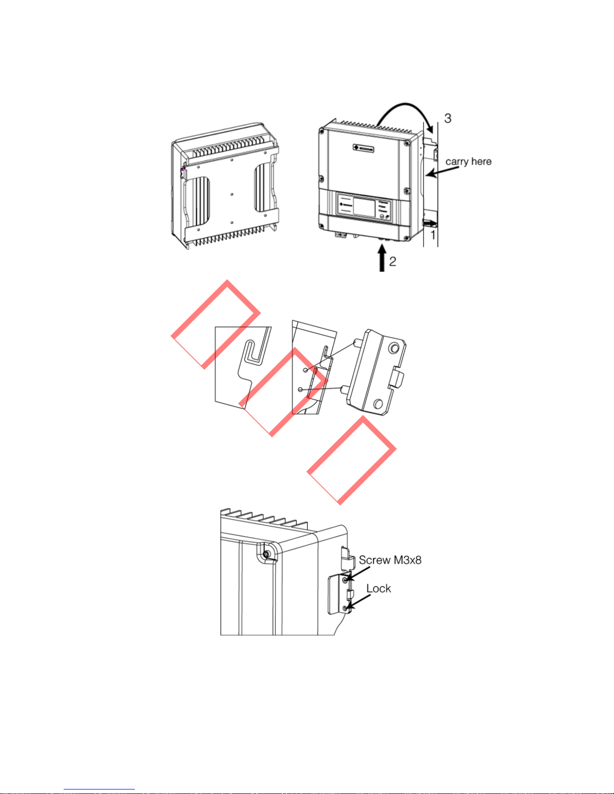
C Hold the inverter by the groove on the heat sink.
Figure 3.3.2-2
D Place the inverter on the wall-mounted bracket (as
illustrated below).
已发行
9
Figure 3.3.2-3 Figure 3.3.2-4
Figure 3.3.2-5
E Insert the lock plate pegs into the two holes in the heat-sink,
then fix the inverter with a padlock and screw M3x8.
Figure 3.3.2-6
已发行
10
3.4 Electrical Connection
Connections must be made in compliance with local
regulations and the requirements of local power
authorities/companies.
In accordance with VDE0126-1-1/A1, the inverter incorporates
a Residual Current Monitoring Unit (RCMU) which monitors
residual current from the solar module to the grid side of the
inverter. The inverter can automatically differentiate between
fault current and normal capacitive leakage currents.
3.4.1 Connection to grid (AC side Connection)
A Check the grid (utility) voltage and frequency at the
connection point of the inverter. It should be 230VAC (or
220VAC), 50/60Hz, and single phase.
B Disconnect the breaker or fuse between the PV-inverter
and the utility.
C Connect the inverter to the grid as follows:
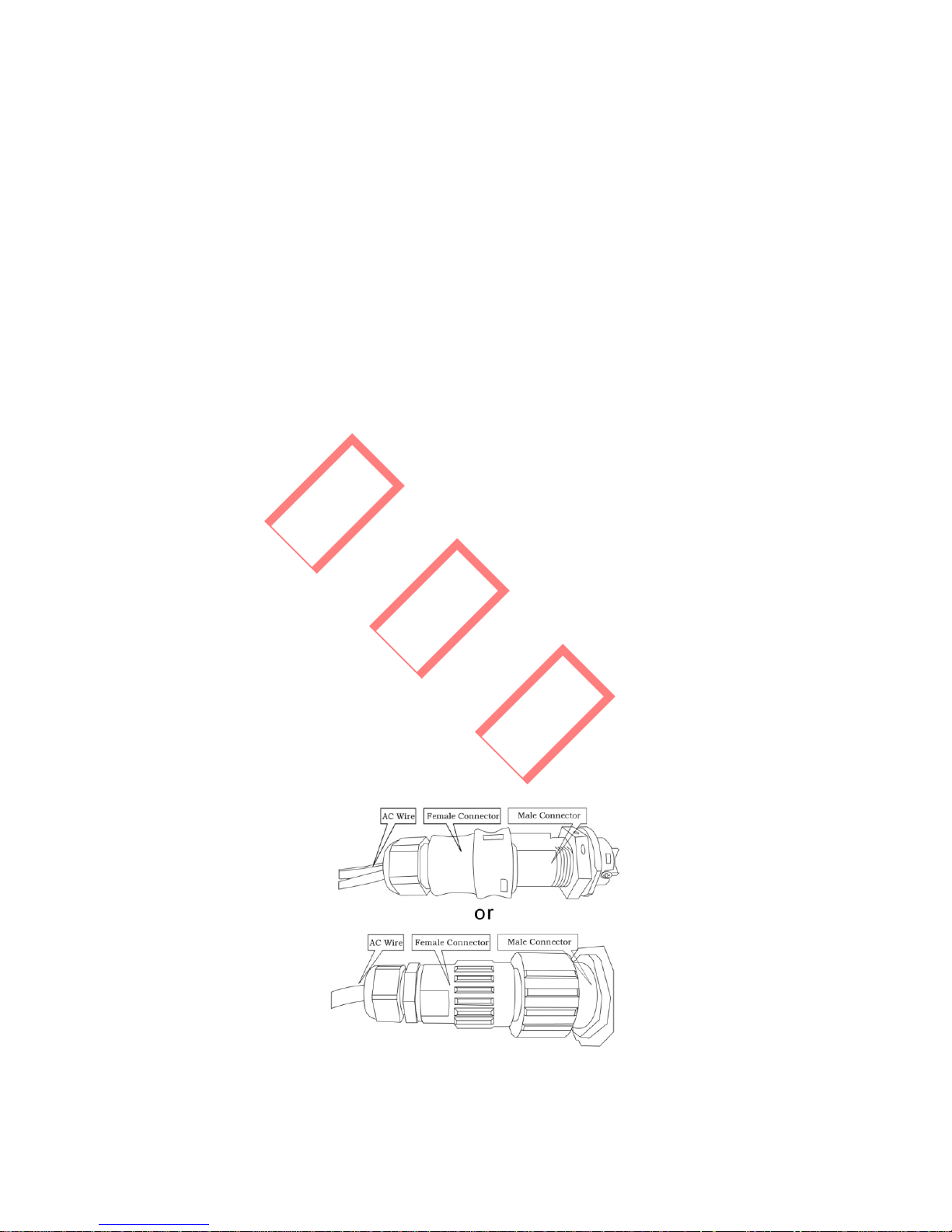
` Switch off the AC breaker.
` Disassemble the female connector of the AC wire
connector and connect the AC wires to the connection
socket as indicated.
Figure 3.4.1-1
已发行
11
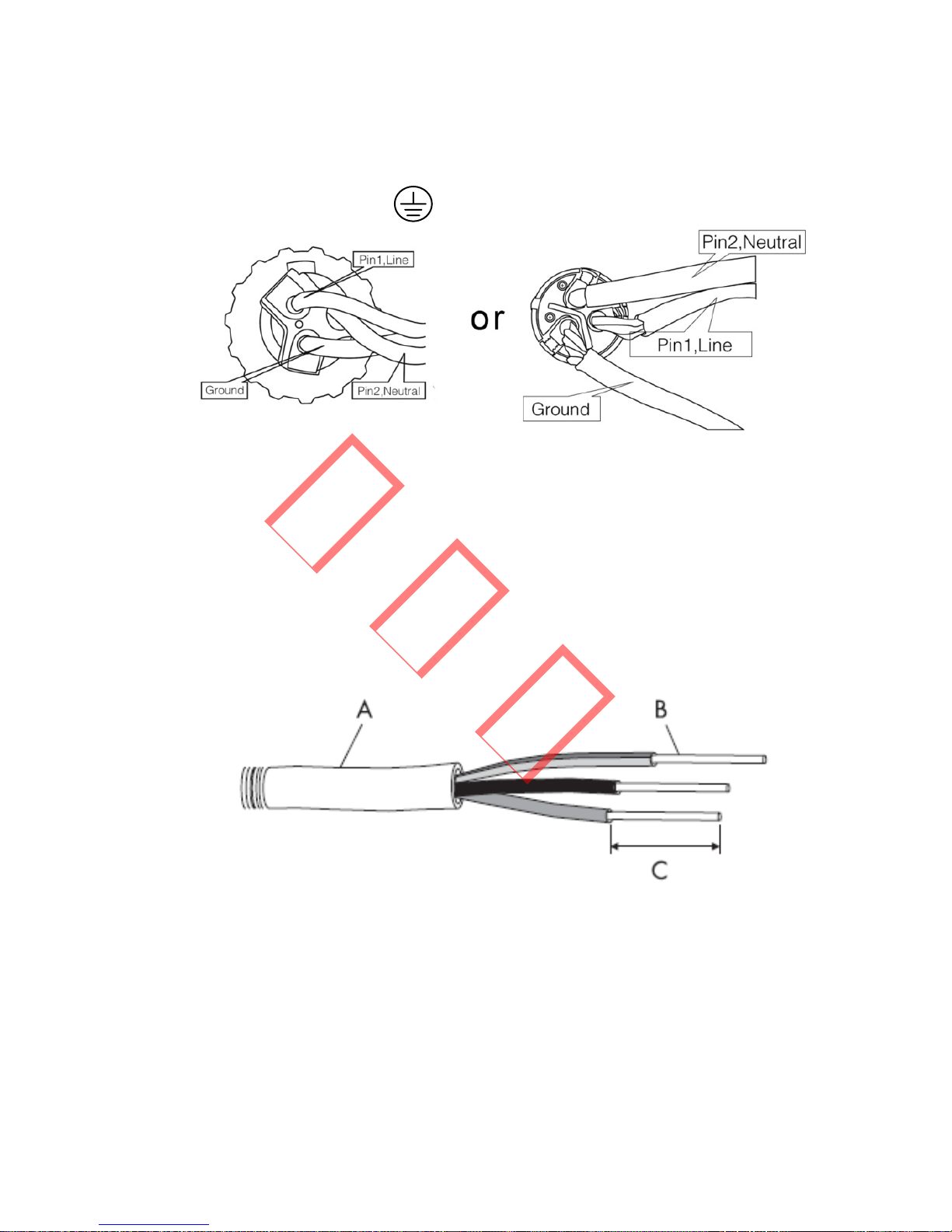
` Insert Line wire to Pin 1, Neutral wire to Pin 2 and
Ground wire to Pin
Figure 3.4.1-2
` After fastening all screws, reassemble the female
connector of the AC wire connector.
` Connect the female connector of the AC wire
connector to the male connector on the inverter.
D Specifications of the AC wires:
Figure 3.4.1-3
已发行
12
Depicted Size
A External diameter of the wire 12mm-25mm
B Sectional area of conducting materials Max.6mm2
C Length of bare wire Approx.10mm
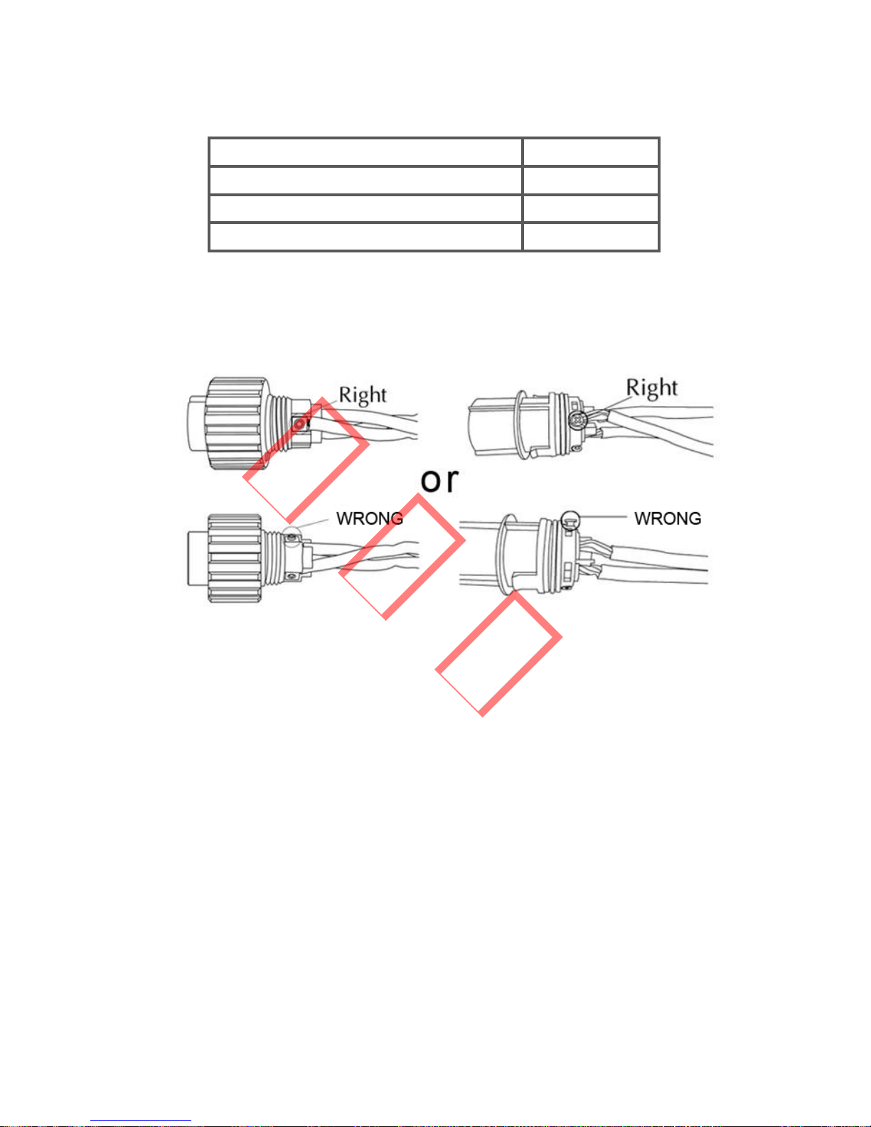
E AC output connection
Tighten the screw with a screw driver until the head of the
screw is inside the connector. Otherwise the wire could be
loose.
Figure 3.4.1-4
3.4.2 DC side connection
A Make sure the maximum open circuit voltage (Voc) of
each PV string does not exceed the inverter’s input voltage
Vmax under any condition.
B Use Amphenol or Multi-contact connectors for the PV
array terminals.
C Connect the positive and negative terminals of the PV
panel to corresponding terminals on the inverter. The DC
terminal on each inverter can bear 20A DC current.
已发行
13
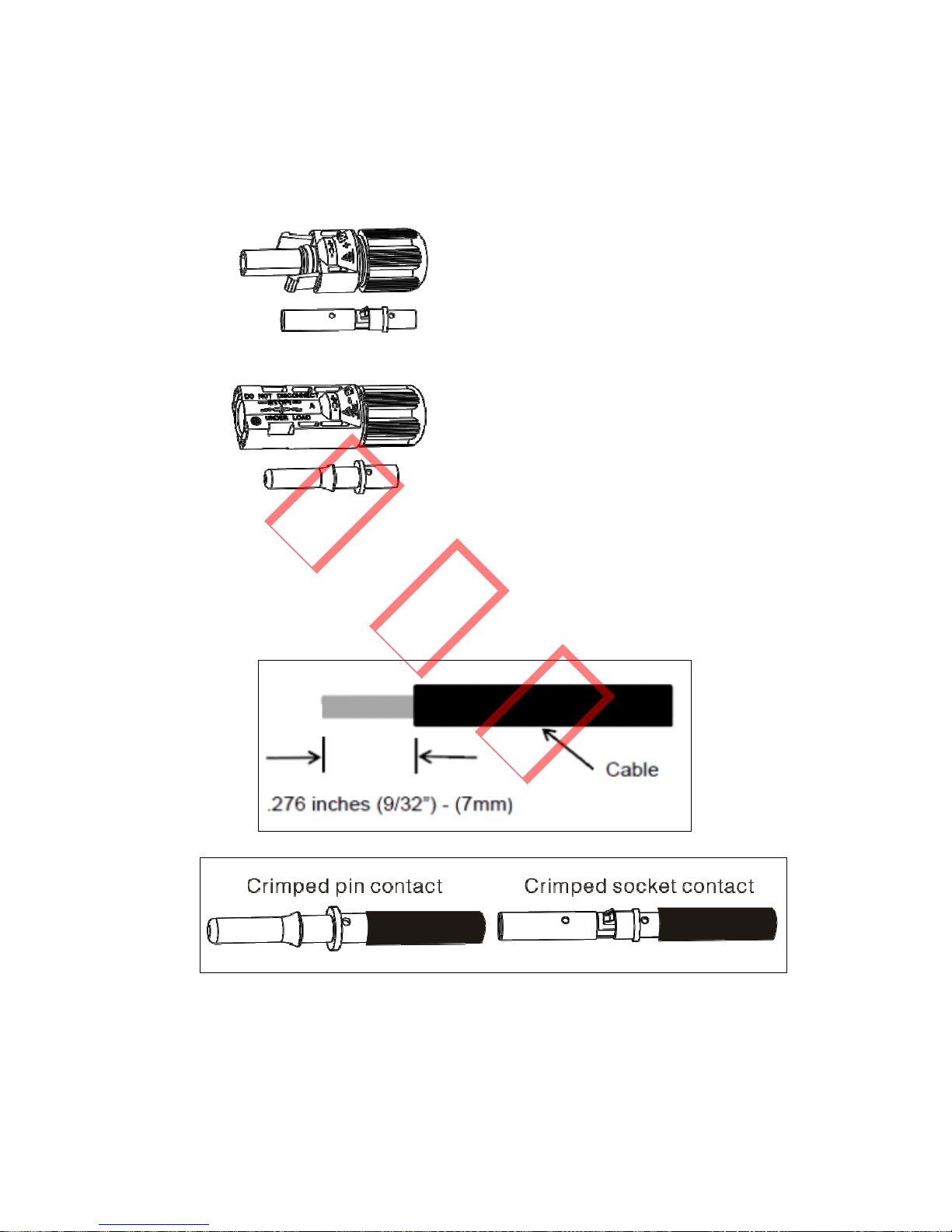
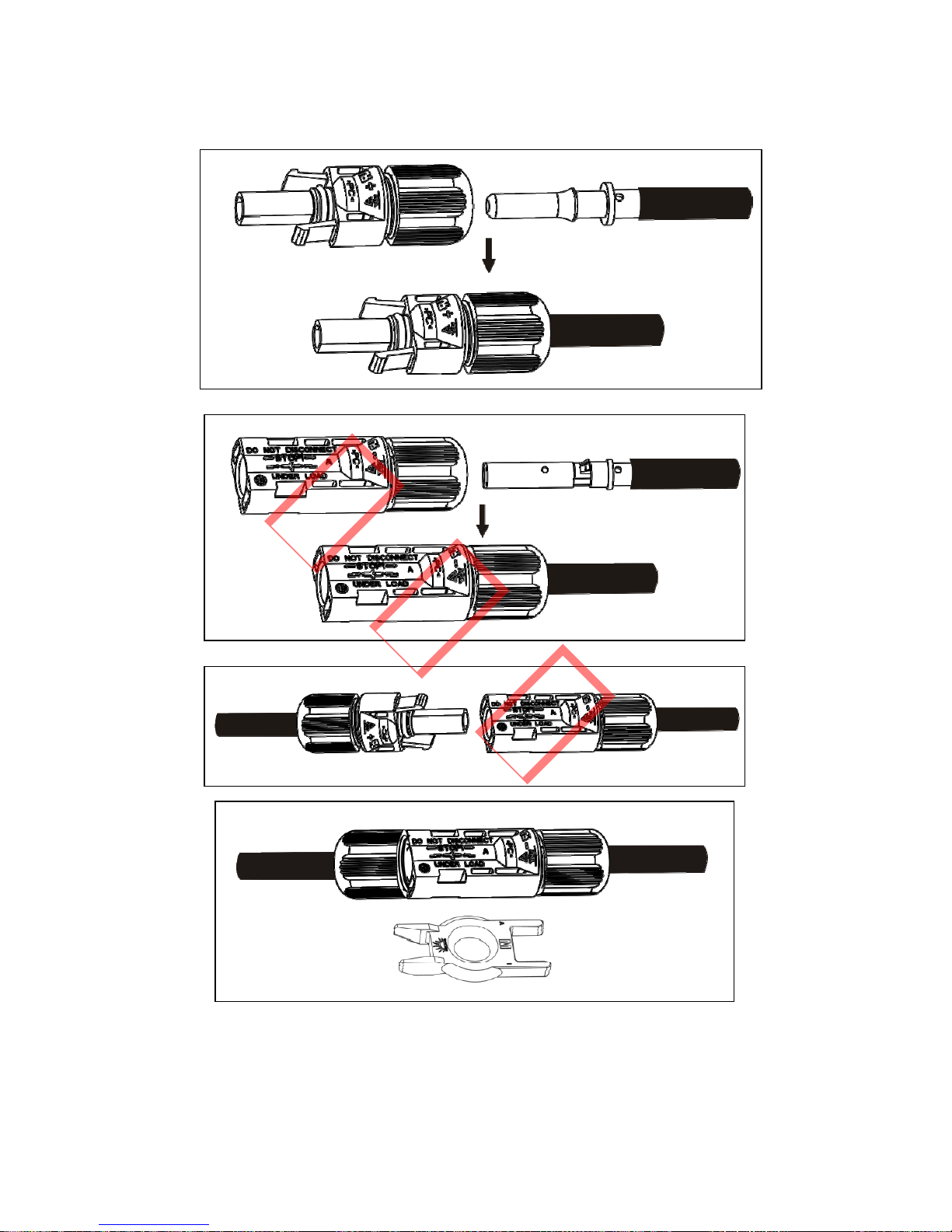
If using Amphenol connectors for the PV array terminals,
install as follows.
Female side connector (PV+) Male side connector (PV-)
Connectors must be installed as a pair, and each cable stripped
and installed as shown below.
已发行
14
Figure 3.4.2-1 Separated by Ring tool
已发行
15
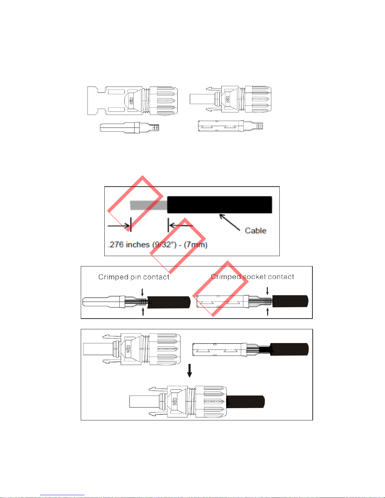
If using Multi-contact connectors for the PV array terminals,
install as follows.
Female side connector (PV+) Male side connector (PV-)
Connectors must be installed as a pair, and each cable stripped
and installed as shown below.
已发行
16
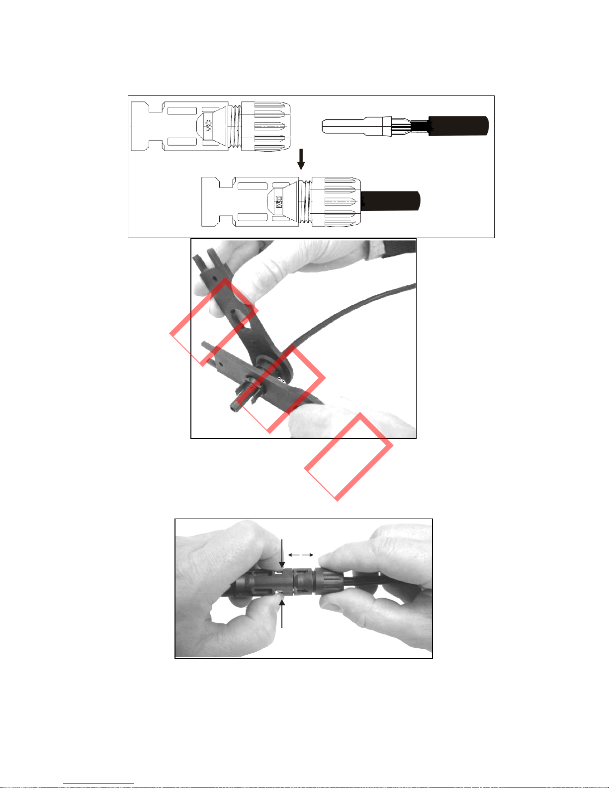
Figure 3.4.2-6
Tighten the screw connection. Then the terminal can be
connected to the inverter side.
Figure 3.4.2-7
已发行
17
Compress the two snap-in springs by hand and release
Where the inverter is equipped with a DC switch, ensure the
switch is in the "OFF" position before connecting the inverter
to PV panels. Switch to "ON" after completing the connection.
Caution:
` Before connecting the PV panels, ensure the plug
connectors have the correct polarity. Incorrect polarity could
permanently damage the unit.
` Checks the short-circuit current of the PV string. The total
short-circuit current of must not exceed the inverter’s
maximum DC current.
` High voltage exists when the PV panel is exposed to the sun.
Secure the terminal connection and, to avoid electric shock,
do NOT touch any exposed components.
3.4.3 RS485 Communication
An RS485 interface is used for multipoint communication. The
EzLogger can monitor and communicate with 50 inverters at
the same time; however the cable length should not exceed
1000 m. The diagram below shows a typical inverter
connection through the RS485 interface.
已发行
 Loading...