

Goodwe GW3600S-BP, GW5000S-BP User Manual
APP (iOS)Official Website APP (Android)
340-00087-02 Version: 1.0
SBP SERIES USER MANUAL
AC-COUPLED BATTERY STORAGE RETROFIT
No.189 Kun Lun Shan Road, SND, Jiangsu, China.
www.goodwe.com
service@goodwe.com
Jiangsu GoodWe Power Supply Technology Co.,Ltd

TABLE OF CONTENTS
021.2 SAFETY & WARNINGS
041.3 PRODUCT OVERVIEW
011.1 OPERATION MODES INTRODUCTION
INTRODUCTION
01
052.1 UNACCEPTABLE INSTALLATIONS
052.2 PACKING LIST
062.3 MOUNTING
062.3.1 SELECT MOUNTING LOCATION
072.3.2 MOUNTING
082.4 ELECTRICAL WIRING CONNECTION
082.4.1 BATTERY CONNECTION
102.4.2 ON-GRID & BACK-UP CONNECTION
122.4.3 EZMETER & CT CONNECTION
132.5 DRED CONNECTION
INSTALLATION INSTRUCTIONS
02
163.1 WIFI CONFIGURATION & WIFI RELOAD
173.2 PV MASTER APP OPERATION
173.3 CEI AUTO-TEST INSTRUCTION
MANUAL OPERATION
03
184.1 ERROR MESSAGE AND TROUBLESHOOTING
244.2 DISCLAIMER
284.3 WARINING QUICK CHECK LIST
294.4 TECHNICAL PARAMETERS AND CERTIFICATES
OTHERS
04
TABLE OF CONTENTS
1.1 OPERATION MODES INTRODUCTION
The S-BP series inverters of Jiangsu GoodWe Power Supply Technology Co., Ltd. (hereinafter called
as GoodWe) strictly comply with related safety rules for product design and testing. Please read and
follow all the instructions and cautions on the inverter or user manual during installation, operation or
maintenance, as any improper operation might cause personal or property damage.
GoodWe S-BP series bi-directional inverter is designed for both indoor and outdoor use, which could
be used with or without existing grid-tied inverter systems to store energy with batteries.
Energy produced from grid-tied inverters shall be used to optimize self-consumption, then charge
battery, exceed power from grid-tied system could export to grid. Loads will be supported in priority
by grid-tied system, then battery power, exceed consumption power will be drained from grid.
S-BP system normally has the following operation modes based on your configuration and layout
conditions
1.2 SAFETY & WARNING
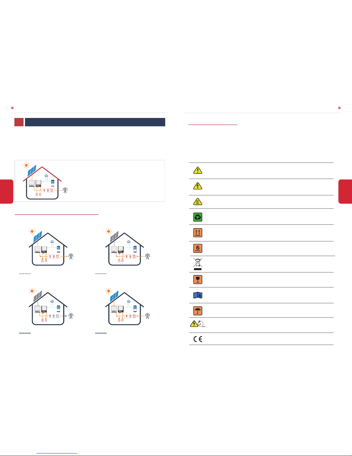
• SYMBOLS EXPLANATION
INTRODUCTION01
Caution!
Failing to observe a warning indicated in this manual may result in injury.
Danger of high voltage and electric shock!
Components of the product can be recycled.
This side up! The package must always be transported, handled and stored in such a
way that the arrows always point upwards.
Danger of hot surface!
No more than six (6) identical packages being stacked on each other.
Product should not be disposed as household waste.
The package/product should be handled carefully and never be tipped over or slung.
Refer to the operating instructions.
Keep dry! The package/product must be protected from excessive humidity and must
be stored under cover.
Inverter will be touchable or operable after minimum 5 minutes of being turned off or
totally disconnected, in case of any electrical shock or injury.
CE Mark
Note: the introduction describes a general behavior of S-BP
system. The operation mode can be adjusted on GoodWe PV
Master APP depends on the system layout. Below are the
general operation modes for S-BP system:
Energy from grid-tied inverters optimize loads, then
charge battery, exceed power export to grid.
Mode Ⅰ
When energy from grid-tied inverters is weak, battery
discharge to support loads in priority, together with grid.
Mode Ⅱ
When grid power fails, battery will discharge to support
Back-Up Loads.
Mode Ⅲ
Battery can be charged by grid, and charging
time/power can be set flexibly on PV Master APP.
Mode Ⅳ
02
INTRODUCTION INTRODUCTION
01
INTRODUCTION
• SAFETY WARNING
Any installation and operation on inverter must be performed by qualified electricians, in compliance
with standards, wiring rules or requirements of local grid authorities or companies (like AS 4777 and
AS/NZS 3000 in Australia).
Before any wiring connection or electrical operation on inverter, all battery and AC power must
be disconnected from inverter for at least 5 minutes to make sure inverter is totally isolated to
avoid electric shock.
The temperature of inverter surface might exceed 60℃ during working, so please make sure it
is cooled down before touching it, and make sure the inverter is untouchable for children
Do not open inverter cover or change any components without GoodWe’s authorization,
otherwise the warranty commitment for the inverter will be invalid.
The inverter, with built-in RCMU, will exclude possibility of DC residual current to 6mA, thus in
the system an external RCD (type A) can be used(≥30mA).
IN Australia, output of backup side in switchbox should be labeled ‘Main switch UPS supply’,
the output of normal load side in switch box should be labeled ‘main switch inverter supply’.
Usage and operation of the inverter must follow instructions in this user manual, otherwise the
protection design might be useless and warranty for the inverter will be invalid.
Appropriate methods must be adopted to protect inverter from static damage. Any damage
caused by static is not warranted by GoodWe.
In Australia, the inverter internal switching does not maintain neutral integrity, which must be
addressed by external connection arrangements like in the system connection diagram for
Australia on page 16.
03
INTRODUCTION
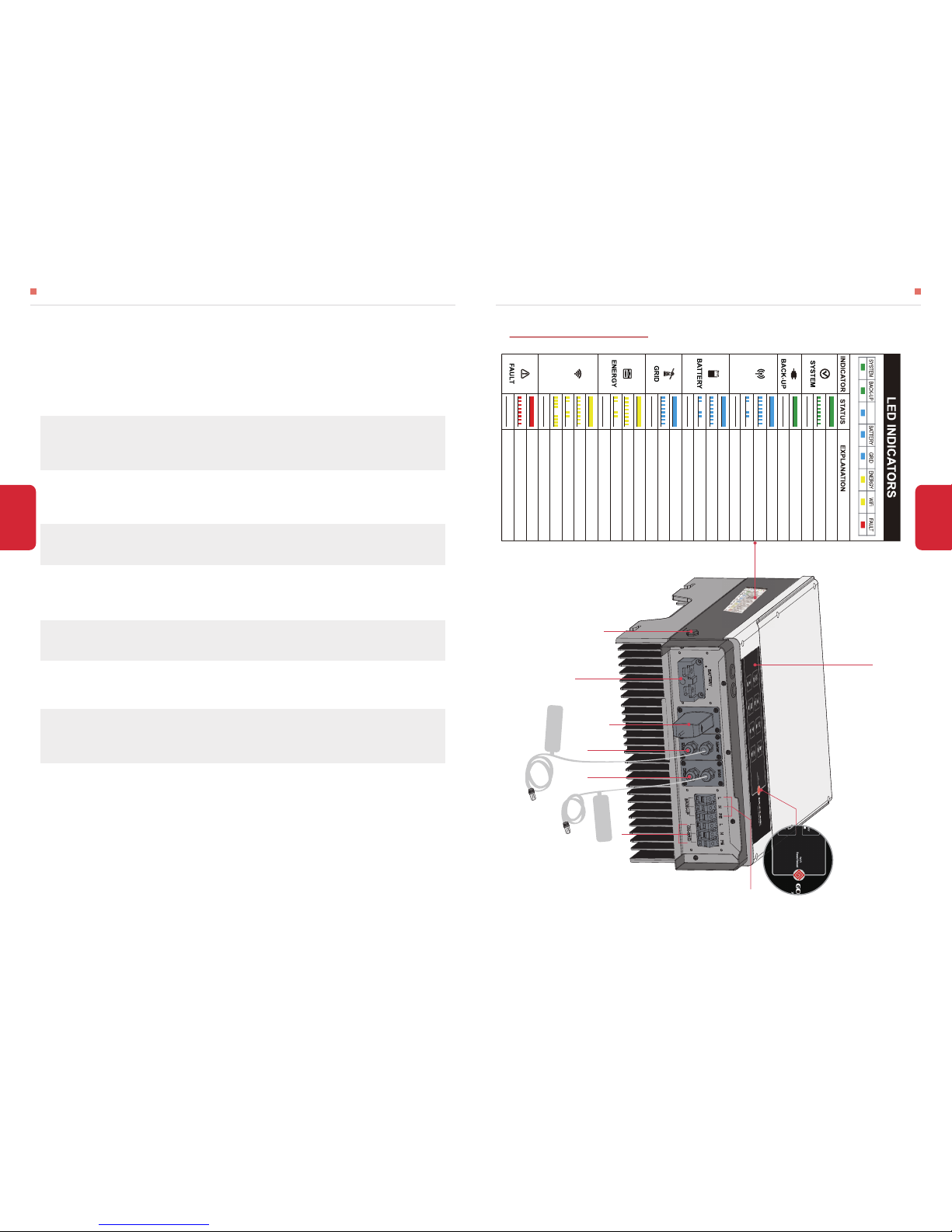
Battery Terminals
Wi-Fi Box
Reserved
RS485
DRED
Back-Up Port
On-Grid Port
BMS Communication Cable
EzMeter Communication Cable
Exhaust Valve
LED Lable
WiFi Reset/Reload Button
1.3 PRODUCT OVERVIEW
04
BLINK 2 = Wi-Fi NO T CO NNECT TO RO UTER
BLINK 4 = Wi-Fi SERVER PROBLEM
OFF = Wi-Fi NOT ACTIVE
ON = FAULT HAS OCCURRED
BLINK = OVERLOAD OF BACK-UP OUTPUT /
REDUCE LOAD
OFF = NO FAULT
COM
Wi-Fi
ON = BMS AND METER COMMUNICATION OK
BLINK1 = METER COMMUNICATION OK, BMS
COMMUNICATION FAIL
BLINK2 = BMS COMMUNICATION OK, METER
COMMUNICATION FAIL
OFF = BMS AND METER COMMUNICATION FAIL
ON = BATTERY IS CHARGING
BLINK 1 = BATTERY IS DISCHARGING
ON = Wi-Fi CONNECTED / ACTIVE
BLINK 1 = Wi-Fi SYSTEM RESETTING
ON = SYSTEM IS READY
BLINK = SYSTEM IS STARTING UP
OFF = SYSTEM IS NOT OPERATING
ON = BACK-UP IS READY / POWER AVAILABLE
OFF = BACK-UP IS OFF / NO POWER AVAILABLE
COM
To EzMeter
To Battery
BLINK 2 = BATTERY IS LOW / SOC IS LOW
OFF = BATTERY IS DISCONNECTED / NOT ACTIVE
ON = GRID IS ACTIVE AND CONNECTED
BLINK = GRID IS ACTIVE BUT NOT CONNECTED
OFF = GRID IS NOT ACTIVE
ON = CONSUMING ENERGY FROM GRID / BUYING
BLINK 1 = SUPPLYING ENERGY TO GRID / ZEROING
BLINK 2 = SUPPLYING ENERGY TO GRID / SELLING
OFF = GRID NOT CONNECTED OR SYSTEM NOT
OPERATING
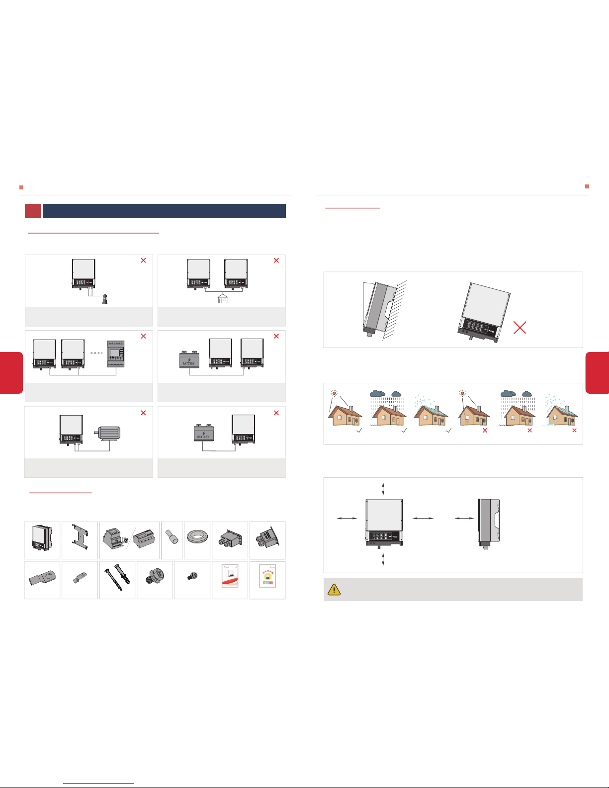
2.1 UNACCEPTABLE INSTALLATIONS
2.2 PACKING LIST
INSTALLATION INSTRUCTIONS INSTALLATION INSTRUCTIONS
05
06
Please avoid the following installations, which will damage the system or the inverter.
On receiving the inverter, please check to make sure all the components as below are not missing or
broken.
BACK-UP SIDE CANNOT CONNECT TO GRID BACK-UP CANNOT CONNECT IN PARALLEL.
ONE EZMETER CANNOT CONNECT TO MULTI INVERTERS
ONE BATTERY BANK CANNOT BE CONNECT TO
MULTI INVERTERS.
CANNOT CONNECT TO INCOMPATIBLE BATTERIES
ON-GRID OR BACK-UP SIDE CANNOT CONNECT TO ANY AC
GENERATOR.
2.3.1 SELECT MOUNTING LOCATION
2.3 MOUNTING
Rule 1. Inverter should be installed on a solid surface, where is suitable for inverter’s dimensions and
weight.
Rule 2. Inverter installation should stand vertically or lie on a slop by max 15° (Pic 1)
Rule 3. Ambient temperature should be lower than 45℃
Rule 4. The installation of inverter should be protected under shelter from direct sunlight or bad
weather like snow, rain, lightning etc. (Pic 2)
Rule 5. Inverter should be installed at eye level for convenient maintenance.
Rule 6. Product label on inverter should be clearly visible after installation.
Rule 7. Leave enough space around inverter following the values on pic 3.
Direct Sunlight Exposure to Rain Exposure to SnowNo Direct Sunlight No Exposure to Rain No Exposure to Snow
Pic 2
Upward----------
Downward------
Front-------------
Both sides-------
300mm
500mm
300mm
200mm
300mm
300mm
200mm 200mm
500mm
Pic 3
Inverter cannot be installed near flammable, explosive or strong electro-magnetic
equipment.
[1]
Pic 1
For inverter’s protection and convenient maintenance, mounting location for inverter should be
selected carefully based on the following rules:
INSTALLATION INSTRUCTIONS02
15°
Wall-mounted
Bracket×1Inverter×1 AC cover×1 Battery cover × 1EzMeter & CT × 1
User manual×1Expansion bolts×6
Hexagon head
screw × 2 Pan head screw × 6PE terminal × 1
Battery terminal × 2
Quick Installation
Guide×1
Back-Up On-Grid
Load
Back-Up
Back-Up
EzMeter
Battery Battery
Back-Up On-Grid
Generator
Battery
Incompatible battery
Connection
terminal × 6
Insulation ring×2
 Loading...