

Goodwe EM Series, GW5048-EM, GW3648-EM, GW3048-EM User Manual
Google playiOS App Store
Franciscusdreef 42C
3565AC Utrecht
340-00053-00
4.6
4.7
4.8 DRED Connection
4.9 Earth Fault Alarm
4.10
4.12 special backup application
13
14
14
14
15
15
6 CEI Auto Test introduction
7
9 Trouble shooting
10
11
12
16
18
19
20
24
25
27
1 Introduction
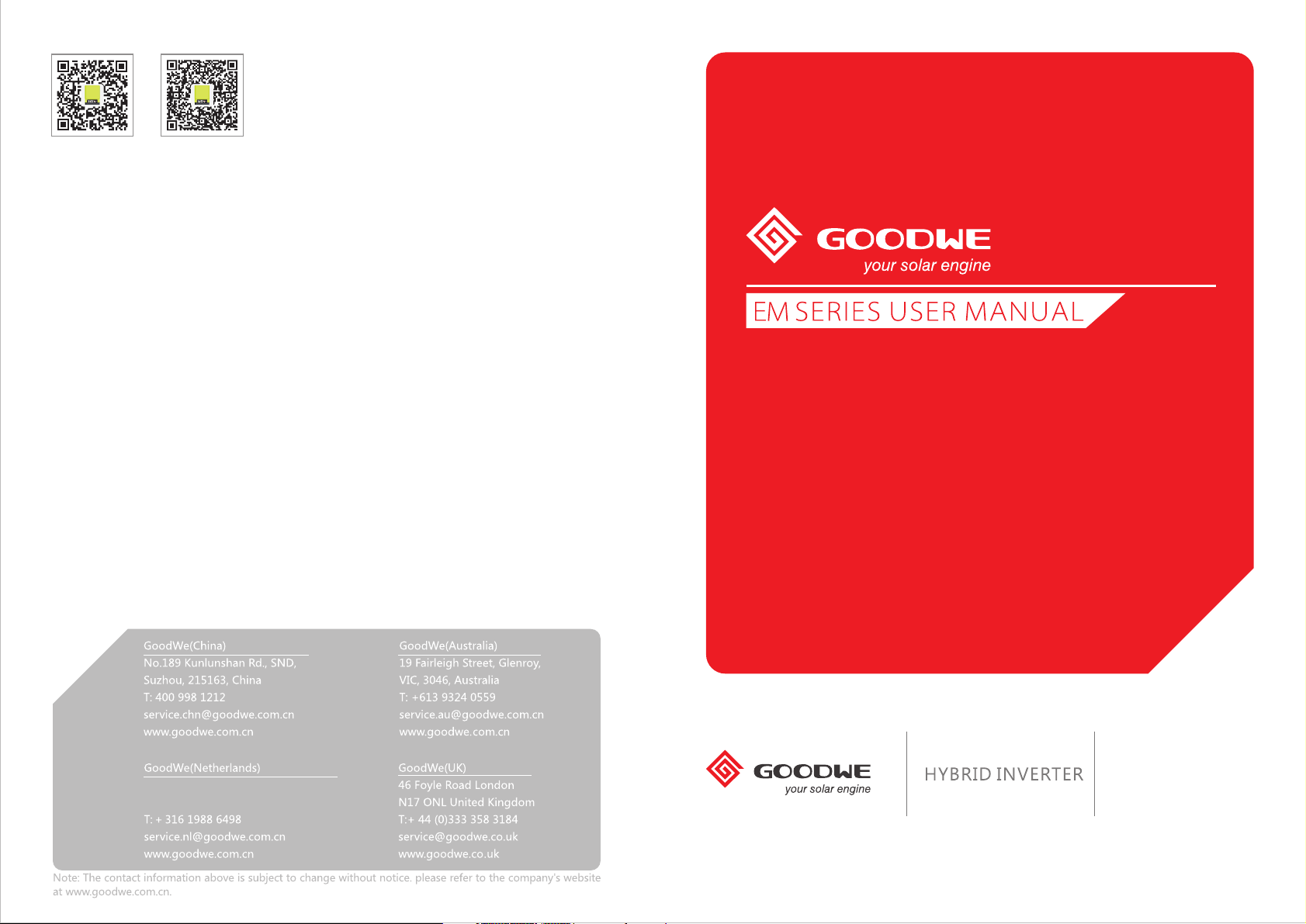
The EM series inverters (hybrid) are bidirectional which apply to PV system with battery to store energy.
Energy produced by the PV system is used to optimize self-consumption; excess energy is used to charge the batteries, and then feed
into the public grid when the PV energy is adequate,
When PV energy output is insufficient to support connected loads, the system automatically discharge energy from the batteries if
battery capacity is abundant. If the battery energy is insufficient to meet own consumption requirements, electricity will be drawn
from the public grid.
EM series inverter is design for both indoor and outdoor use.The
Figure 1-1 Basic hybrid PV system overview
2 Important Safety Warning
Before using the inverter, please read all instructions and cautionary markings on the unit and this manual. Store the manual where
it can be accessed easily.
The EM series inverter of Jiangsu GoodWe Power Supply Technology Co. Ltd. (hereinafter referred to as GoodWe) strictly conforms to
related safety rules in design and test.
Safety regulations relevant to the location shall be followed during installation, operation and maintenance.
Improper operation may have a risk of electric shock or damage to equipment and property.
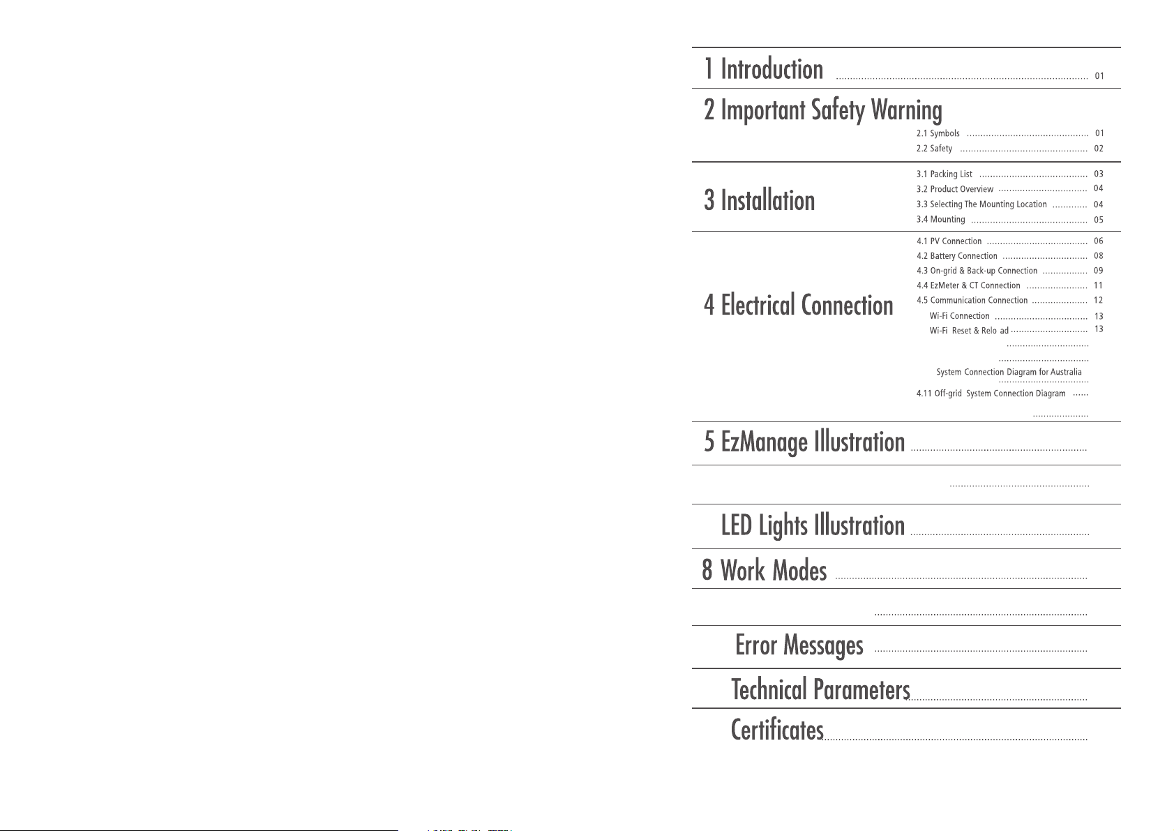
2.1 Symbols
Caution!
Failure to observe a warning indicated in
this manual may result in injury.
Danger of high voltage and electric shock!
Danger of hot surface!
Components of the product can be recycled.
This side up; the package must always be
transported, handled and stored in such a way
that the arrows always point upwards.
No more than six (6) identical packages may
be stacked on each other.
Product should not be disposed as
household waste.
Refer to the operating instructions
Signals danger due to electrical
shock and indicates the time (5
minutes) to allow after the
inverter has been turned off and
disconnected to ensure safety in
any installation operation.
The package/product should be handled
carefully and never be tipped over or slung.
Keep dry; the package/product must be
protected from excessive humidity and must be
stored under cover.
CE Mark
2.2 Safety
● Installation, maintenance and connection of inverters must be performed by qualified personnel, in compliance with local electrical
standards, wiring rules and the requirements of local power authorities and/or companies (for example : AS 4777 and AS/NZS
3000 in Australia).
● To avoid electric shock, DC input and AC output of the inverter must be terminated at least 5 minutes before performing any
installation or maintenance.
● The temperature of some parts of the inverter may exceed 60℃ during operation. To avoid being burnt, do not touch the inverter
during operation. Let it cool before touching it.
● Ensure children are kept away from inverters.
● Do not open the front cover of the inverter. Apart from performing work at the wiring terminal (as instructed in this manual),
touching or changing components without authorization may cause injury to people, damage to inverters and annulment of the
warranty.
● Static electricity may damage electronic components. Appropriate method must be adopted to prevent such damage to the
inverter; otherwise the inverter may be damaged and the warranty annulled.
● Ensure the output voltage of the proposed PV array is lower than the maximum rated input voltage of the inverter; otherwise the
inverter may be damaged and the warranty annulled.
● When exposed to sunlight, the PV array generates dangerous high DC voltage. Please operate according to our instructions, or it
will result in danger to life.
● PV modules should have an IEC61730 class A rating.
● If the equipment is used in a manner not specified by the manufacturer, the protection provided by the equipment may be
impaired.
● Completely isolate the inverter before maintaining. Completely isolate the inverter should :Switch off the DC switch, disconnect
the PV terminal, disconnect the battery terminal, and disconnect the AC terminal.
● Prohibit to insert or pull the AC and DC terminals when the inverter is running.
● In Australia, the inverter internal switching does not maintain the neutral integrity, neutral integrity must be addressed by external
connection arrangements like the example proposed in the diagram 4.10.
● In Australia, the output of backup side in switchbox should be labeled 'main switch UPS supply', the output of normal load side in
switchbox should be labeled 'main switch inverter supply'.
01
02
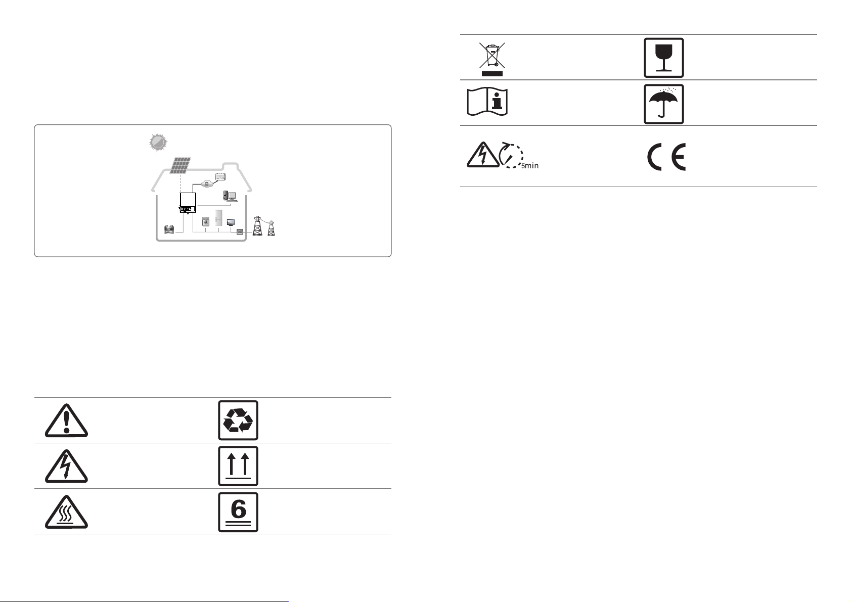
● Don’t connect EM series in the following ways:
①Back-up port should not be connected to grid;
②Back-up port should not be connected in parallel;
③The single PV panel string should not be connected to two or more inverters.
Back-Up
① ② ③
On-Grid
Back-Up
Back-Up
Load
3 Installation
PV PV
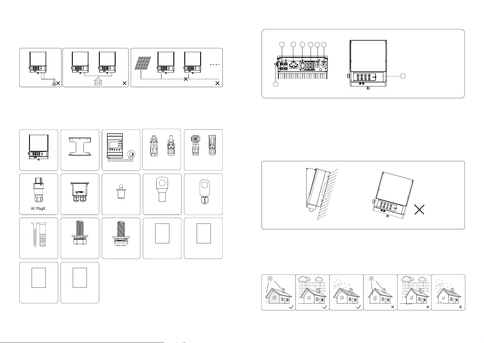
3.2 Product Overview
1 2
7
3
4
1.
5
6
PV input terminals
2. Battery input terminals
3. Wi-Fi Box port
4. Communication port
5. Back-Up port
6. On-Grid port
7. DC Switch (Optional)
8
8. LED Lable
3.1 Packing List
Before installation, please inspect the unit. Be sure that nothing inside the package is damaged. You should have received the
following items inside of package:
or
Negative DC
PE terminal × 1
Configuration
Wi-Fi
Wi-Fi Configuration×1
Inverter×1
2
Expansion Bolts×6
User
manual
Wall-mounted
Bracket×1
Battery cover × 1
Hexagon head
screw × 2
EzManage
Instruction
EzMeter & CT × 1
Waterproof terminal × 2
Pan head screw × 6
or
Positive DC Plug×2
Battery terminal × 2
Instruction
of
Fast
Installation
Quick Installation
Guide×1
Plug×2
3.3 Selecting The Mounting Location
Mounting location should be selected based on the following aspects:
n
at
● The install
dimensions.
● Mount on a solid surface.
● Select a well ventilated place sheltered from direct sun radiation.
● Install vertically or tilted backward by max 15°. The device cannot be installed with a sideways tilt. The connection area must point
downwards. Refer to Figure 3.3-1.
In order to achieve optimal performance, the ambient temperature should be lower than 45 °C.
●
● For the convenience of checking the LED lights and possible maintenance activities, please install the inverter at eye level.
● Inverters should NOT be installed near inflammable and explosive items. Any strong electro-magnetic equipment should be kept
away from installation site.
● Product label and warning symbol shall be clear to read after installation.
● Please avoid direct sunlight, rain exposure, snow lay up when install.
o
i
method and mounting location must be suitable for the inverter's weight and
Max
15°
Figure 3.3-1
User Manual×1
EzManage Instruction ×1
No direct sunlight
No Rain Exposure
No Snow Lay up
Direct Sunlight
Rain Exposure
Snow Lay up
03 04
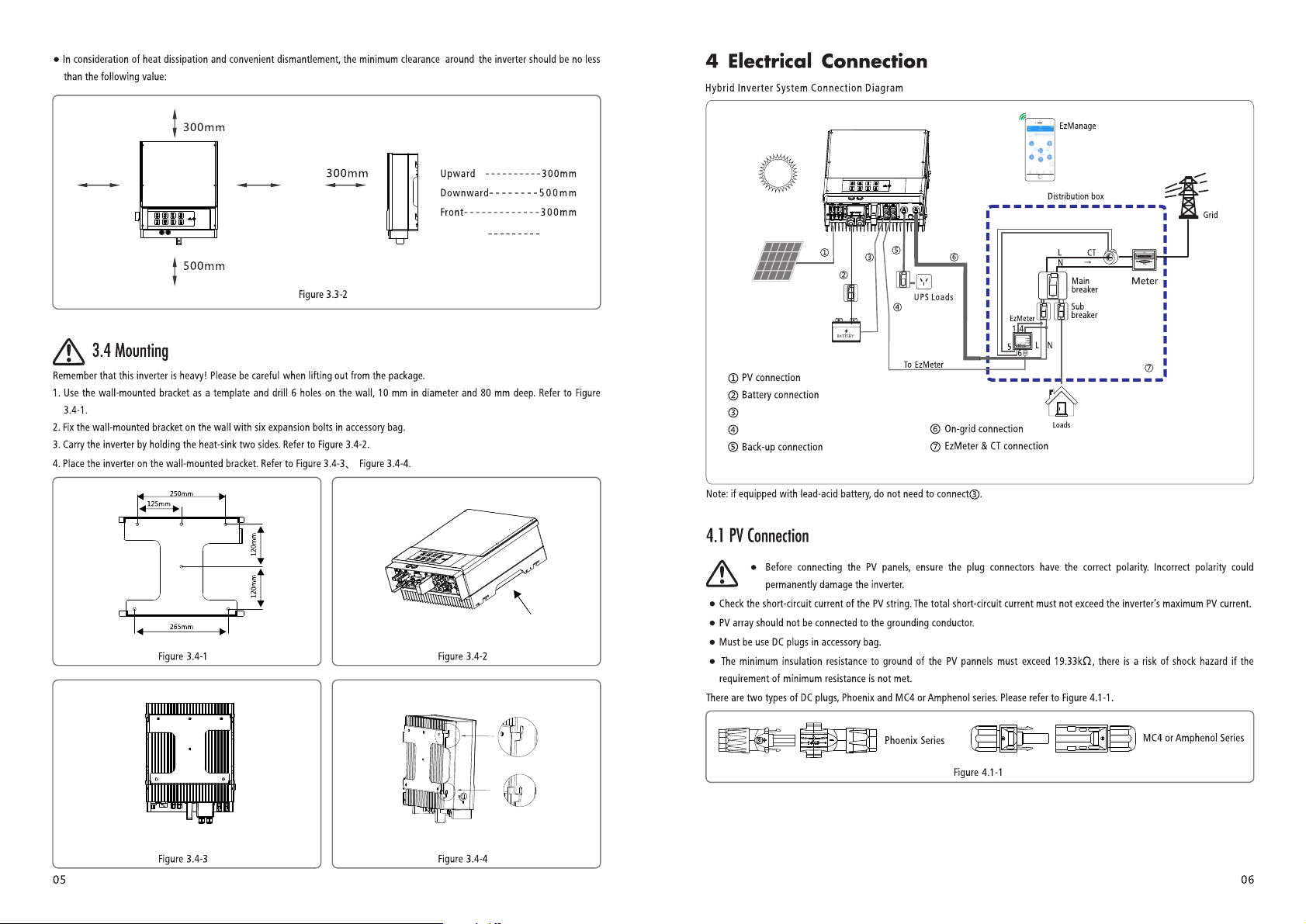
200mm
200mm
Both sides 2 00mm
To Battery communication cable
To EzMeter communication cable
T
o
B
a
ttery
House
Grid
 Loading...