

Goodwe Smart DT Series, GW4000-DT, GW9000-DT, GW8000-DT, GW10KN-DT User Manual
...
app
Smart DT SERIES USER MANUAL
GoodWe(China)
No.189 Kunlunshan Rd.,SND,
Suzhou,215163,China
T: 400 998 1212
service.chn@goodwe.com.cn
www.goodwe.com.cn
GoodWe(Netherlands) GoodWe(UK)
service.nl@goodwe.com.cn
www.goodwe.com.cn
Note: The information above is subject to change without prior notice,details refer to www.goodwe.com.cn.
GoodWe(Australia)
service.au@goodwe.com.cn
www.goodwe.com.cn
enquiries@goodwe.co.uk
www.goodwe.co.uk
SOLAR INVERTER

1 Symbols
........................................................................................................ 01
2 Safety and Warning
................................................................ 01
3 Installation
3.1 Mounting Instruction
3.2 Overview and Packaging
3.3 Inverter Installation
3.4 Electrical Connection
............................ 02
........................ 02
.............................. 04
............................... 05
4 System Operation
................................................ 13
....................... 13
............................................... 18
......................... 18
................ 19
5 Troubleshooting
4.1 LED Lights
4.2 User Interface and Controls
4.3 Error Code
4.4 WiFi Reset & WiFi Reload
4.5 Power limiting function setting
.................................................................... 21
6 Technical Parameters and Block Diagram
7 Maintenance
8 Certificates
6.1 Technical Parameters
6.2 Block Diagram
7.1 Cleaning the Fans
7.2 Checking the DC Switch
7.3 Checking the Electrical Connection
.............................................................................................. 25
................................ 21
........................................... 23
..................................... 24
......................... .. 24
........... 24

1 Symbols
Refer to the operating instructions
Caution! - Failure to observe a warning
indicated in this manual may result in minor
or moderate injury.
Danger of high voltage and electric shock!
Danger of hot surface!
Product should not be disposed as normal
household waste.
Components of the product can be recycled.
This side up - The package must always be
transported, handled and stored in such a
way that the arrows always point upwards.
No more than six (6) identical packages be
stacked on each other.
The package/product should be handled
carefully and never be tipped over or
slung.
Keep Dry – The package/product must be
protected from excessive humidity and
must accordingly be stored under cover.
●Ensure the output voltage of the proposed PV array is lower than the maximum rated input voltage of the inverter; otherwise the
inverter may be damaged and the warranty will be annulled.
●When exposed to sunlight, the PV array will generate very high voltage which will cause potential danger to people. Please strictly
follow the instruction we provided.
●PV modules should have an IEC61730 class A rating.
●If the equipment is used in a manner not specified by the manufacturer, the protection provided by the equipment may be impaired.
●Completely isolate the equipment should : switch off the DC switch, disconnect the DC terminal, and disconnect the AC terminal or
AC breaker.
●Prohibit inserting or pulling the AC and DC terminals when the inverter is working.
●Only DC connectors provided by GoodWe are permitted to use, otherwise the inverter may be damaged and the warranty will be
annulled.
●Person could access to inverter status through mobile phone and computer display please refers to chapter 3.4.4 and 3.4.5. and
error code could be shown not only on inverter LCD display but also mobile phone APP interface.
The inverter can exclude the possibility of DC residual currents to 6mA in the system,Where an external RCD is required in addition
to the built-in RCMU, type A RCD must be used to avoid tripping。
The default photovoltaic module is not grounded.
If there are more than 3 PV strings on input side, an additional fuse installing will be suggested.
Signals danger due to electrical
shock and indicates the time (5
minutes) to allow after the
inverter has been turned off and
disconnected to ensure safety in
any installation operation.
CE Mark
2 Safety and Warning
Smart DT (hereinafter referred to as SDT) series inverter of Jiangsu GoodWe Power Supply Technology Co.,Ltd. ( hereinafter
referred to as GoodWe ) strictly conforms to related safety rules in design and test. As electric and electronic equipment, Safety
Regulation shall be followed during installation and maintenance. Improper operation may bring severe damage to the operator, the
third party and other properties. SDT: Smart Dual-MPPT, Three-Phase).
Installation maintenance and connection of inverters must be performed by qualified personnel,in compliance with local electrical
● ,
standards regulations and there quire ments of local power authorities and /or companies.
,
●
To avoid electric shock, must be terminated AC out put of inverter then terminated DC input disconnected and wait at least 5
minutes before performing any installation or maintenance.
●
The temperature of some parts of the inverter may exceed 60C during operation. To avoid being burnt, do not touch the inverter
during operation. Let it cool before touching it.
●
Keep children away from the inverter.
●
Without permission, open the front cover of the inverter is not allowed. Users should not touch/replace any of the components
except for the DC/AC connectors. GOODWE will not bear any consequences caused by unauthorized actions which will lead to
potential injury to people and damage to inverters.
●
Static electricity may damage electronic components. Appropriate method must be adopted to prevent such damage to theinverter;
otherwise the inverter may be damaged and the warranty will be annulled.
(
O
3 Installation
3.1 Mounting Instruction
● In order to achieve optimal performance, the ambient temperature should be kept lower than 45 °C.
● For the convenience of checking the LCD display and possible maintenance activities, please install the inverter at eye level.
● Inverters should NOT be installed near inflammable or explosive items. Any strong electro-magnetic equipment should be kept
away from installation site.
● Product label and warning symbol shall be clear to read after installation.
● Please do not install inverter under direct sunlight, rain and snow.
Direct Sunlight
Rain Exposure
Snow Lay up
3.2 Overview and Packaging
After opening the package, confirm if it is consistent with specification of inverter you purchased.

3.2.1 Inverter Overview
SDT4~10KW inverter illustration.
②
①
③
④
3.2.2 Package
3.3 Inverter Installation
3.3.1 Selecting the Installation Position
Installation position should be selected based on the following aspects:
⑥
⑤
⑦
⑧
1. PV input terminals
2. Waterproof vent
3. DC Switch(Optional)
4. Wi-Fi&LAN
5. RS485 & GATEWAY
6.
AC output terminal
⑨
7. LED lights
8. LCD display
9. Buttons
● The installation method and mounting location must be suitable for the inverter's weight and dimensions.
● Mount on a solid surface.
● Select a well ventilated place sheltered from direct sun radiation.
●
Install vertically or tilted backward by max 15°. The device cannot be installed with a sideways tilt. The connection area must
point downwards.
Refer to Figure 3.3.1-1.
Figure 3.3.1-1
Inverter×1
AC Junction
Box screw
Antenna×1
Positive DC Plug:SDT4~10KW 2 pairs.
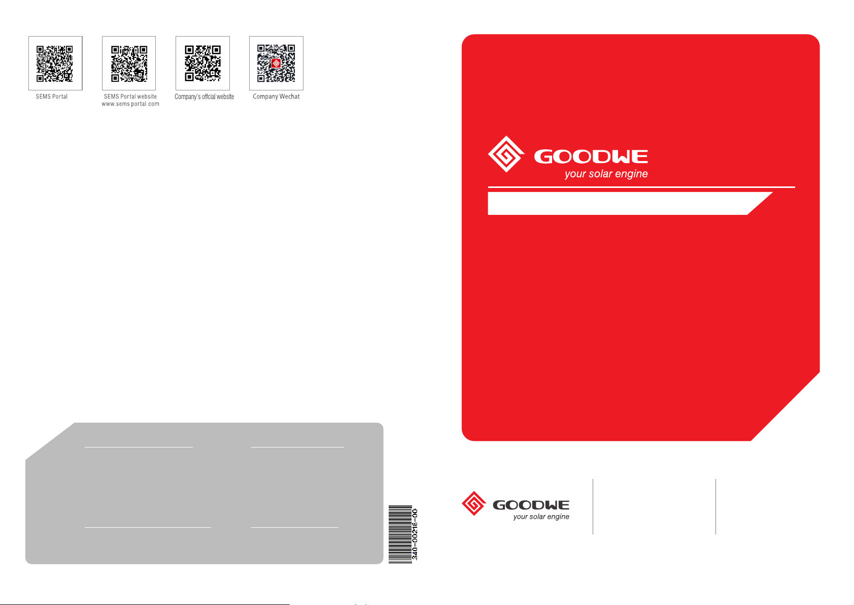
Negative DC Plug:SDT4~10KW 2 pairs.
4PIN terminal: SDT4~10KW: 1pcs for tigo gateway communication
3PIN terminal: SDT4~10KW: 1pcs for RS485 communication
⑤
AC Junction Box :RS485 6pcs; WiFi 12 screw pcs.
⑥
Flat Head Screw: 2pcs(optional).
⑤
Wall-mounted
Bracket×1
AC connector×1
4PIN terminal×1 3PIN terminal×1
Positive DC Plug
Expansion screw×6
①
Negative DC Plug
Flat Head Screw
②
⑥
AC Terminal X6
Fast installation
instructions
User
manual
User manual×1
Quick Installation
Guide×1
● In consideration of heat dissipation and convenient dismantlement, the minimum clearances around the inverter should be no less
than the following value:
The installation position shall not prevent access to the disconnection means.
200mm
500mm 500mm 300mm
500mm
Figure 3.3.1-2
Upward----------200mm
Downward-------500mm
Front--------------300mm
Both sides-------500mm
3.3.2 Mounting Procedure
(1) Use the wall-mounted bracket as a template and drill 6 holes on the wall, 10 mm in diameter and 80 mm deep.
The size of SDT series refer to Figure 3.3.2-1.
(2) Fix the wall mounting bracket on the wall with six expansion bolts in accessory bag.
(3) Hold the inverter by the groove on it.
(4) Place the inverter on the wall-mounted bracket as illustrated in Figure 3.3.2-2、3.3.2-3.
(5)
(6)
457
228.5
refer to Figure 3.3.2-5.
.
refer to Figure 3.3.2-6.
.
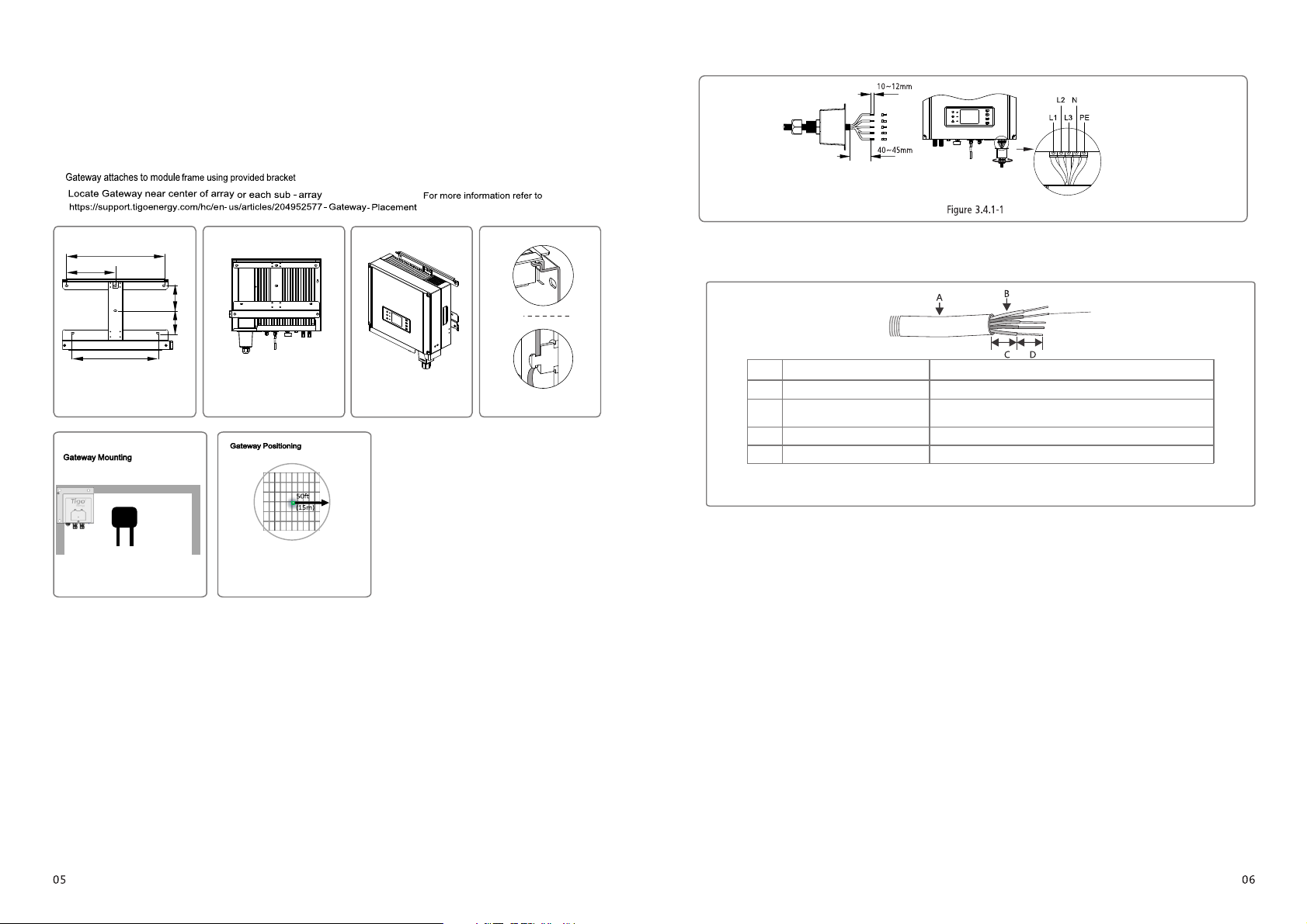
Installation instruction of waterproof coupling series connector please refer to Figure 3.4.1-1.
wire crimpers impose line
Note: TheNlineofGW30K-DTshouldnot beconnected.
AC cable illustration please refer to Figure 3.4.1-2.
fasten screw cap clockwise
Ensure the wire be locked tightly
Live Wire
L1 ----- 1
L2 ----- Live Wire 2
L3 ----- Live Wire 3
N ------ Neutral Wire
PE------ Earth Wire
117.5
104.5
400
Figure 3.3.2-1 Figure 3.3.2-2
Figure 3.3.2-5
Figure 3.3.2-6
Figure 3.3.2-3 Figure 3.3.2-4
3.4 Electrical Connection
3.4.1 Connection to Grid (AC Side Connection)
(1) Check the grid voltage and frequency, select a suitable safety standard from inverter that comply with this requirements.
(2) Add breaker or fuse to AC side, the specification should be more than 1.25 times of rated AC output current.
(3) The PE line of inverter should be connected to the earth, make sure the impedance of neutral wire and earth wire less than 10 ohm.
(4) Disconnect the breaker or fuse between the inverter and the utility.
(5) The integrated leakage current detection device of the inverter can detect external leakage current in real time. When the detected
leakage current exceeds the limit value, inverter will quickly disconnect with the grid. If the leakage current protection device is
installed externally, the action current should be 300mA or higher.
(6) Connect the inverter to the grid as follows:
(7) Fix (Torque: 2~2.5 N.m) the connector of AC cable to the corresponding terminals.
(8) Neutral conductor shall be blue, line conductor shall be black or brown (preferred), protective earth bonding line shall be yellow-green.
(9) The AC line construction shall be such that if the cord should slip in its anchorage, placing a strain on conductors, the
protective earthing conductor will be the last to take the strain. such as the PE line is longer than L and N.
Grade Description
A O.D.
Copper Conductor Material
B
Sectional Area*
C
Wire Length
Bare Wire Length
D
Annealed copper wire
Value
SDT: 4~10kW: 11~23mm
SDT: 4~10kW: 4~10mm²
45mm around
12mm around
Figure 3.4.1-2
 Loading...