

Goodwe GW015K-DT, GW020K-DT, GW017K-DT, GW010K-DT, GW025K-DT User Manual
...
DT/Smart DT SERIES USER MANUAL
350 -0001 4-05
SO LAR INVERT ER
Official Website
Global Service Hotline:+86 4009-281-333
GoodWe(Europe)
Mürwikerstr. 59
24943 Flensburg Germany
T: +49 461 5897 0235
europe@goodwe.com.cn
www.goodwe.de
GoodWe(China)
No.189 Kunlunshan Rd.,SND,
Suzhou, 215163, China
T: +86 512 6239 6771
service@goodwe.com.cn
www.goodwe.com.cn
GoodWe(Australia)
74 Tarana Avenue,
Glenroy VIC 3046, Australia
T: +61 3 9972 9938
australia@goodwe.com.cn
www.goodwe.de
GoodWe(UK)
93 Caversham Place
Sutton Coldfield B73 6HW
T: +44 12 1238 0053
uk@goodwe.com.cn
www.goodwe.com.cn
GoodWe (Netherlands)
Zevenwouden 194 ,
3524 CX Utrecht, the Netherlands
T: +31 6 1988 6498 +31 6 1784 0429
service@goodwe.com.cn
www.goodwe.com.cn
Company Wechat

1 Symbols
2 Safety and Warning
3 Installation
4 System Operation
5 Troubleshooting
6 Technical Parameters and Block Diagram
7 Maintenance
8 Certificates
3.1 M ounti ng Inst ructi on
3.2 O vervi ew and Pac kagin g
3.3 I nvert er Inst allat ion
3.4 E lectr ical Co nnect ion
4.1 LED Lights
4.2 User Interface and Controls
4.3 Error Code
4.4 WiFi Reset & WiFi Reload
. .. ... ..... ..... ..... ..... ..... ..... . ... .... ... ..... .... 01
... ..... ..... ..... ..... .. 02
... ..... ..... ..... ... 02
... ..... ..... ..... ..... .... 03
... .... ... ... ... ..... .... 05
... ..... ..... ..... ..... ..... ...... ..... .... 11
... ..... ..... ..... ... 11
. ... ..... ...... ... ..... ..... ..... ..... . ... 16
... ..... ..... ..... ..... 16
.. ... ..... ..... ..... ..... ..... ...... ..... ..... ..... ..... ..... ..... ..... ..... .. ... ..... .... 01
... ..... ..... ..... ..... ..... ...... ..... ..... ..... ..... ..... ..... .... 17
6.1 Technical Parameters
6.2 Block Diagram
... ..... ..... ..... ..... ..... . 18
... ..... ..... ..... ..... ..... ...... .... 23
... ..... ..... ... .... ..... ..... ...... ..... ..... ..... ..... ..... ..... ..... .... 25... ....
7.1 Cleaning the Fans
7.2 Checking the DC Switch
... ..... ..... ..... ..... ..... ..... 24
... ..... ..... ..... ..... .. 25

Caution! - Failure to observe a warning
indicated in this manual may result in minor
or moderate injury.
Danger of high voltage and electric shock!
Danger of hot surface!
Product should not be disposed as normal
household waste.
CE Mark
Components of the product can be recycled.
This side up - The package must always be
transported, handled and stored in such a
way that the arrows always point upwards.
No more than six (6) identical packages be
stacked on each other.
The package/product should be handled
carefully and never be tipped over or
slung.
Keep Dry – The package/product must be
protected from excessive humidity and
must accordingly be stored under cover.
Signals danger due to electrical shock and indicates the time (5 minutes) to allow after the
inverter has been turned off and disconnected to ensure safety in any installation operation.
1 Symbols
DT/ Smart DT (hereinafter referred to as SDT) series inverter of Jiangsu GoodWe Power Supply Technology Co.,Ltd. ( hereinafter
referred to as GoodWe ) strictly conforms to related safety rules in design and test. As electric and electronic equipment, Safety
Regulation shall be followed during installation and maintenance. Improper operation may bring severe damage to the operator, the
third party and other properties. (DT: Dual-MPPT, Three-Phase, covering 09kW/10kW/12kW/15kW/17kW/20kW/25kW; SDT: Smart
Dual-MPPT, Three-Phase, covering 4kW/5kW/6kW.)
●Installation, maintenance and connection of inverters must be performed by qualified personnel, in compliance with local electrical
standards, regulations and the requirements of local power authorities and/or companies.
●To avoid electric shock, DC input and AC output of the inverter must be terminated at least 5 minutes before performing any
installation or maintenance.
O
●The temperature of some parts of the inverter may exceed 60 C during operation. To avoid being burnt, do not touch the inverter
during operation. Let it cool before touching it.
● Keep children away from the inverter.
●Without permission, open the front cover of the inverter is not allowed. Users should not touch/replace any of the components
except for the DC/AC connectors. GOODWE will not bear any consequences caused by unauthorized actions which will lead to
potential injury to people and damage to inverters.
●Static electricity may damage electronic components. Appropriate method must be adopted to prevent such damage to the inverter;
otherwise the inverter may be damaged and the warranty will be annulled.
●Ensure the output voltage of the proposed PV array is lower than the maximum rated input voltage of the inverter; otherwise the
inverter may be damaged and the warranty will be annulled.
01 02
2 Safety and Warning
3 Installation
3.1 Mounting Instruction
● In order to achieve optimal performance, the ambient temperature should be kept lower than 45 °C.
● For the convenience of checking the LCD display and possible maintenance activities, please install the inverter at eye level.
● Inverters should NOT be installed near inflammable or explosive items. Any strong electro-magnetic equipment should be kept
away from installation site.
● Product label and warning symbol shall be clear to read after installation.
● Please do not install inverter under direct sunlight, rain and snow.
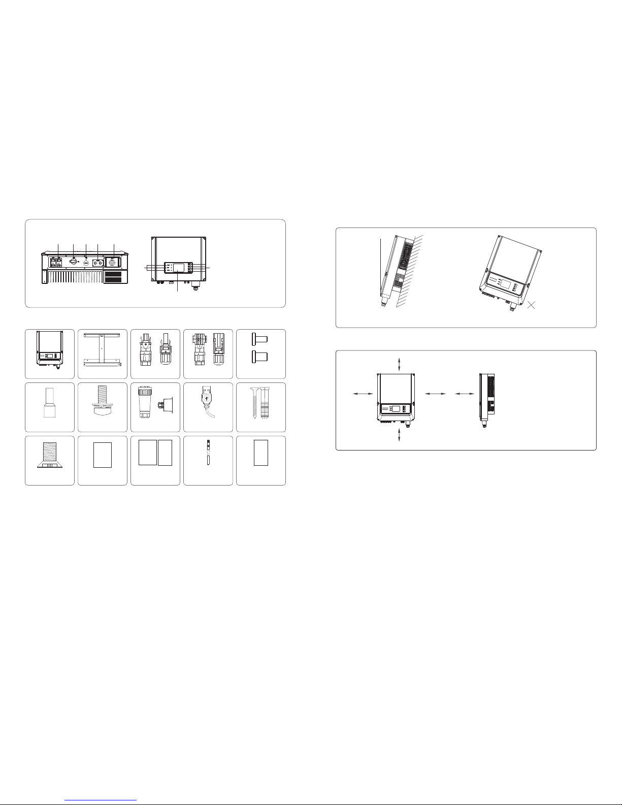
3.2 Overview and Packaging
After opening the package, confirm if it is consistent with specification of inverter you purchased.
3.2.1 Inverter Overview
① ② ③ ④ ⑤
⑥
⑦
⑧
DT Series inverter illustration.
1. PV input terminals
2. DC Switch (Optional)
3. USB port
4. RS485 port or
WiFi antenna port
5. AC output terminal
6. LCD display
7. LED lights
8. Buttons
●When exposed to sunlight, the PV array will generate very high voltage which will cause potential danger to people. Please strictly
follow the instruction we provided.
●PV modules should have an IEC61730 class A rating.
●If the equipment is used in a manner not specified by the manufacturer, the protection provided by the equipment may be impaired.
●Completely isolate the equipment should : switch off the DC switch, disconnect the DC terminal, and disconnect the AC terminal
or AC breaker.
●Prohibit inserting or pulling the AC and DC terminals when the inverter is working.
●Person could access to inverter status through mobile phone and computer display please refers to chapter 3.4.4 and 3.4.5.
Direct Sunlight
Rain Exposure
Snow Lay up
03 04
(1) Use the wall-mounted bracket as a template and drill 6 holes on the wall, 10 mm in diameter and 80 mm deep. The inverter sizes
of DT series please refer to Figure 3.3.2-1, and the size of SDT series refer to Figure 3.3.2-2.
(2) Fix the wall mounting bracket on the wall with six expansion bolts in accessory bag.
(3) Hold the inverter by the groove on it, (DT models please refer to Figure 3.3.2-3, and SDT models refer to Figure 3.3.2-4.)
(4) Place the inverter on the wall-mounted bracket as illustrated in Figure 3.3.2-5、3.3.2-6、3.3.2-7.
3.3.2 Mounting Procedure
Upward------ ----200mm
Downward-------500mm
Front--------------300mm
Both sides-------500mm
Figure 3.3.1-2
200 mm
500 mm
500 mm 500 mm 300 mm
● In consideration of heat dissipation and convenient dismantlement, the minimum clearances around the inverter should be no less
than the following value:
Figure 3.3.1-1
3.3 Inverter Installation
3.3.1 Selecting the Installation Position
Installation position should be selected based on the following aspects:
● The installation method and mounting location must be suitable for the inverter's weight and dimensions.
● Mount on a solid surface.
● Select a well ventilated place sheltered from direct sun radiation.
*Positive DC Plug: 09~12kW 4 pairs; 15~25kW 6 pairs; 4~6kW 2 pairs.
*Negative DC Plug: 09~12kW 4 pairs; 15~25kW 6 pairs; 4~6kW 2 pairs.
*DC Connector Protecting Cover: 09~25kW 2 pairs; 4~6kW none.
WiFi Connection
Guide×1
(WiFi model only)
Expansion screw×6
Flat Head Screw×5
User manual×1
DC connector
protecting cover*
AC Terminal X6
AC Junction Box
screw X5
AC connector×1
or
USB data cable×1
3.2.2 Package
Inv erter×1
Wall-mounted
Bracket×1
Positive DC Plug*orNegative DC Plug*
or
User
manual
Warranty card×1
Quick Installation
Guide×1
Warranty
card
Fast installation
instructions
① ② ③ ④ ⑤
⑥
⑦
⑧
SDT Series inverter illustration.
1. PV input terminals
2. DC Switch (Optional)
3. USB port
4. RS485 port or
WiFi antenna port
5. AC output terminal
6. LCD display
7. LED lights
8. Buttons
●
point downwards.
Install vertically or tilted backward by max 15°. The device can not be installed with a sideways tilt. The connection area must
Refer to Figure 3.3.1-1.
WiFi Connection
Guide
Max
15°
Antenna×1
(WiFi model only)

05 06
There are two AC connector brands for inverter,---VACONN Series and Waterproof Coupling Series, please refer to Figure 3.4.1-1.
Installation instruction of VACONN series connector please refer to Figure3.4.1-2.
Figure 3.4.1-1
VACONN Series
Waterproof Coupling Series
10m m
Inverter
Fastening five screws
to ensure each screw head
is not exceeding the surface
fasten screw cap clockwise
Figure 3.4.1-2
Pin1 ---- Live Wire 1 in
Pin3 ---- Live Wire 2 Pin4 ---- Live Wire 3
Pin5----- Earth Wire
P 2 ---- Neutral Wire
3.4 Electrical Connection
3.4.1 Connection to Grid (AC Side Connection)
(1) Check the grid voltage and frequency, select a suitable safety standard from inverter that comply with this requirements.
(2) Add breaker or fuse to AC side, the specification should be more than 1.25 times of rated AC output current.
(3) The PE line of inverter should be connected to the earth, make sure the impedance of neutral wire and earth wire less
than 10 ohm.
(4) Disconnect the breaker or fuse between the inverter and the utility.
(5) Connect the inverter to the grid as follows:
Installation instruction of waterproof coupling series connector please refer to Figure 3.4.1-3.
AC cable illustration please refer to Figure 3.4.1-4.
wire crimpers impose line
L1 ----- 1
L2 ----- Live Wire 2
L3 ----- Live Wire 3
N ------ Neutral Wire
PE------ Earth Wire
Live Wire
Figure 3.4.1-3
10~12mm
fasten screw cap clockwise
Value
DT: 18~25mm; SDT: 11~20mm
DT: 4~10mm²; SDT: 4~8mm²
12mm around
Grade Description
A O.D.
B Conductor Material Sectional Area
C Bare Wire Length
*
Figure 3.4.1-4
A
B
C
Tighten the screws
Figure 3.3.2-1
Figure 3.3.2-5 Figure 3.3.2-6 Figure 3.3.2-7
Figure 3.3.2-3
177163.5
400
457
228.5
Figure 3.3.2-2
457
228.5
400
117.5
104.5
Figure 3.3.2-4
Model
GW010K-DT
GW012K-DT
GW015K-DT
GW009K-DT
GW017K-DT
GW020K-DT
GW025K-DT
Conductor Material Sectional Area
2
4~10mm
2
4~10mm
2
4~10mm
2
4~10mm
2
4~10mm
2
6~10mm
2
6~10mm
*Value of Conductor Material Sectional Area refers to the following table
 Loading...