

Goodwe EzLogger Pro SERIES User Manual

340-00027-00
EzLogger Pro
Monitoring Data Logger
EzLogger Pro SERIES USER MANUAL
GOODWE (Australia)
19 Faireleigh Street, VIC,
3046, Australia
Tel: +61 3 9324 0559 (after-sales service)
sales@goodwe.com.cn
service.au@goodwe.com.cn
GOODWE (United Kingdom)
46 Foyle Road London N17 0NL
United Kingdom
Tel: 44 (0)333 358 3184
enquiries@goodwe.co.uk
service@goodwe.co.uk
Tel: +31 6 1988 6498 (after-sales service)
Note: The above contact details are subject to change without notice. Please visit our company's
official website www.goodwe.com.cn for details.
Tel: 400-998-1212 (after-sales service)
Company Website Company WeChat
GOODWE (China)
189 Kunlunshan Rd, SND,
Suzhou, China
GOODWE (Netherlands)
Zevenwouden 194,
3524 CX Utrecht, the Netherlands
sales@goodwe.com.cn
service.nl@goodwe.com.cn
sales@goodwe.com.cn
service.chn@goodwe.com.cn

5.3 ..........................................................................................................Program Upgrade
Table of Contents
Table of Contents
01
Chapter I: Safety Precautions
.....................................................................................................
1.2 Schematic Symbols ..........................................................................................................
1.1 Safety Instructions ............................................................................................................
01
01
02
............................................................................................
Chapter II: Product Introduction
2.2 Appearance Description ................................................................................................
2.3 Description of LED Indicators ..........................................................................................
2.1 Product Introduction .......................................................................................................
02
02
05
07
Chapter III: Equipment Installation
.......................................................................................
3.1 Packaging Information ..................................................................................................
3.2 Equipment Installation ..................................................................................................
07
08
Chapter VI: Data Upload and Function Configuration For Wi-Fi EzLogger Pro
...........................................................................................
28
6.1 ...................................................................................How to use Wi-Fi EzLogger Pro
28
6.2 Using ProMate to configure Wi-Fi EzLogger Pro ...................................................
29
4.1 Port Description ...............................................................................................................
4.2 Connection to the Inverter ..........................................................................................
4.3 Connection to the Environmental Monitor and Meter ......................................
4.4 Connection to the Computer ......................................................................................
4.5 Connection to the Ripple Control Receiver ............................................................
4.6 Connection to DRED .......................................................................................................
Chapter IV: Electrical Connection
..........................................................................................
10
10
13
14
14
16
11
5.1 How to Use LAN EzLogger Pro .................................................................................
Chapter : LAN EzLogger Pro Data Upload and Function ConfigurationV
...............................................................................................
17
17
5.2 ......................................................................................EzLogger Pro Configuration
18
27

Table of Contents
9.1 Certification Mark ............................................................................................................
Chapter IX : Certification and Warranty
..........................................................................
9.4 Warranty Conditions ......................................................................................................
9.5 Disclaimer ...........................................................................................................................
37
37
37
37
9.2 Warranty Period ................................................................................................................
9.3 Warranty Certificate ........................................................................................................
37
37
Chapter VII : Website Monitoring
.................................................................................. 30
7.1 Register A New User and Add A Power Station......................................................
30
7.2 View Power Station Information .. ................................................. ..............................
33
.............................................................................. 36
Chapter VIII : Technical Specifications
Chapter I: Safety Precautions
Chapter I: Safety Precautions
1.1 Safety Instructions
EzLogger Pro produced by Jiangsu Power Supply Technology Co., Ltd. (hereinafter GoodWe
“GoodWe”) is designed and tested in strict accordance with the relevant safety regulations,
however, as an electrical and electronic device, the following safety instructions shall be followed at
the time of installation and maintenance, improper operation will cause personal injury and property
damage to the operator and third party.
1. Prevent children from approaching EzLogger Pro.
2. Do not open the upper cover, unauthorized touching or replacement of components may cause
personal injury and damage to EzLogger Pro, in this case, GoodWe will not be liable for such injury
or damage or quality warranty.
3. Static electricity may damage electronic components, so appropriate measures shall be taken to
prevent static electricity.
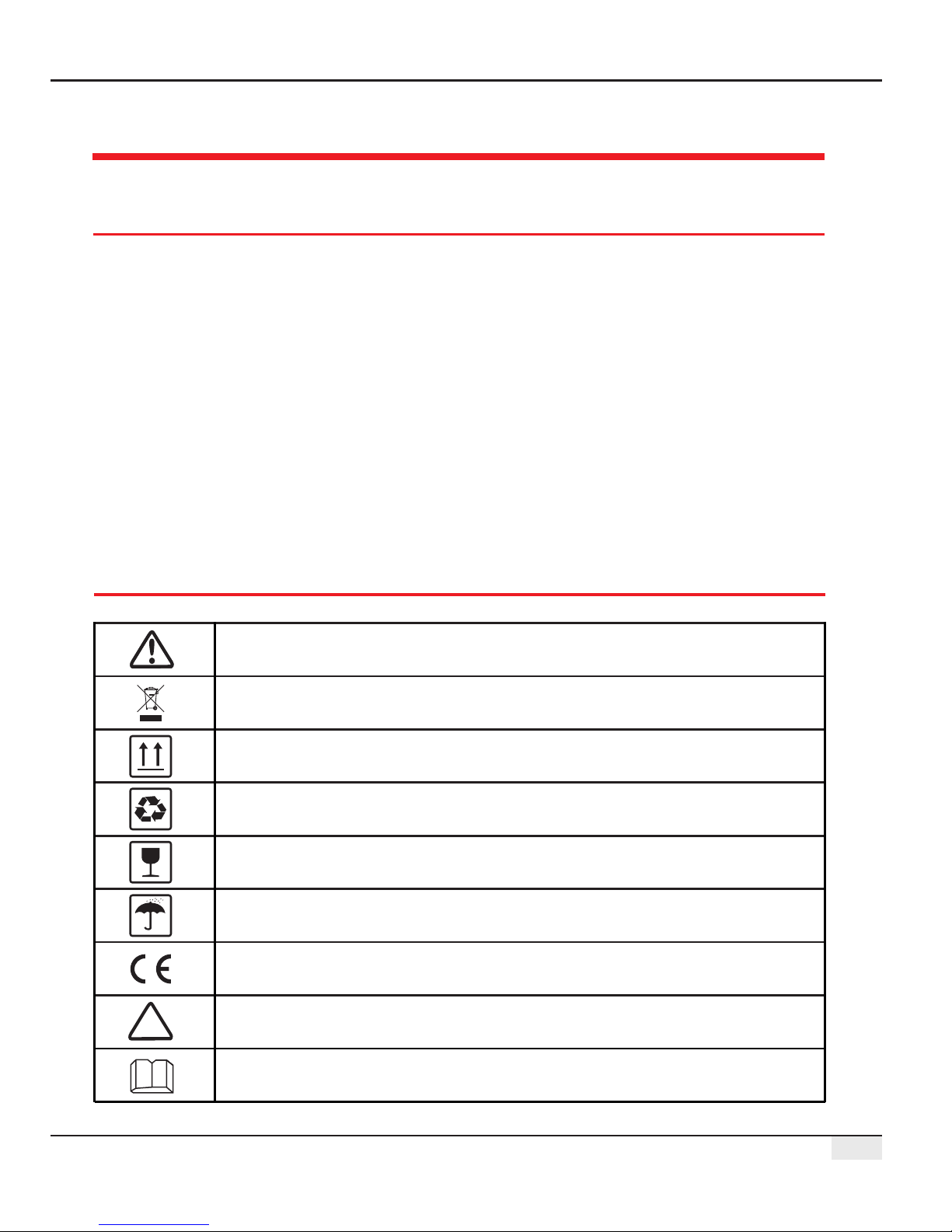
1.2 Schematic Symbols
01
Minor or moderate injury may be caused
It shall not be disposed of as ordinary waste, a special route is required for recycling
Keep upright, and do not tilt or put upside down
Recyclable
Fragile! Handle with care
Keep away from moisture
CE mark
Points of attention
Explanation
Chapter II: Product Introduction
02
Chapter II: Product Introduction
2.1 Product Introduction
EzLogger Pro is a dedicated device for the photovoltaic power generation system monitoring and
management platform, which achieves interface aggregation, data acquisition, data storage, centralized
monitoring, centralized maintenance and other functions for the inverters, environmental monitor, watt-
hour meter and other devices in the photovoltaic power generation system.
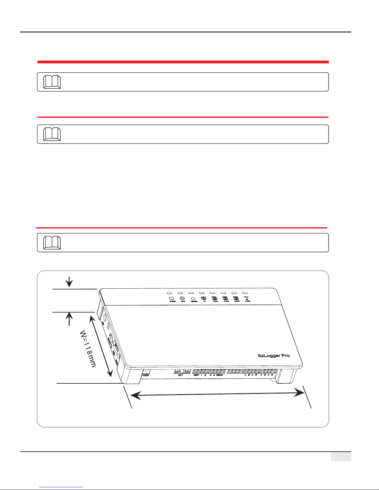
2.2 Appearance Description
Introduce the appearance and function of EzLogger Pro.
Introduce the appearance, specifications and ports of EzLogger Pro.
Introduce the main functions of EzLogger Pro.
Figure 2.2-1 External View of EzLogger Pro
L=190mm
H=37mm
03
Front of the box
Side of the box
2.2 Appearance Description
USB
Micro SD
ANT
Reload
1
2
3
4
Wi-Fi or GPRS antenna connector
SD memory card slot
USB slot
Factory reset button
5
Buzzer sound hole
No.
Port
Port Description
Sound alarm
Figure 2.2-3 Side View of EzLogger Pro Box
Figure 2.2-2 Front View of EzLogger Pro Box
W=118mm
L=190mm
ANT port only can use in Ezlogger Pro with Wi-Fi and Ezlogger Pro with GPRS.

1. SIM card slot
04
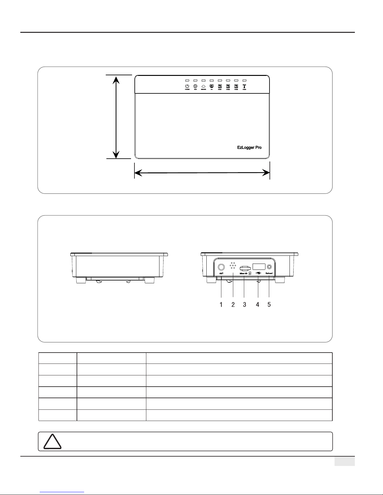
Back of the box
1. Wall mounting hole 2. Rail clip 3. Cooling vents
Top surface of the box
2.2 Appearance Description
1
2
3
Figure 2.2-4 Back View of EzLogger Pro Box
1
Figure 2.2-5 Top View of EzLogger Pro Box
SIM card slot only can use in the EzLogger Pro with GPRS.

05
Bottom surface of the box
1
2
3
4
5
6
7
8
No.
2.3 Description of LED Indicators
8
7
6
5
4 321
Figure 2.2-6 Bottom View of EzLogger Pro Box
2.3 Description of LED Indicators
Introduce the meaning of the LED indicators.
The LED indicators are as follows:
Figure 2.3-1 Explanatory Drawing of LED Indicators

06
2.3 Description of LED Indicators
Description of the LED indicators is as follows:
Blue light On
Blue light Off
Blue light flashes (1s
On/Off alternately)
Blue light continue On or
Off
Blue light flashes (1s
On/Off alternately)
Blue light continue On
Blue light Off
Blue light On
Blue light Off
Blue light On
Blue light flashes (1s
On/Off alternately)
Blue light flashes (1s
On and 3s Off alternately)
Blue light Off
POWER
RUN
SERVER
PC
COM1
Power supply is normal
No power supply
EzLogger Pro is running properly
EzLogger Pro is not running properly
EzLogger Pro is properly connected to the external network server
EzLogger Pro is properly connected to the router, but not
connected to the external network server
EzLogger Pro network is not connected
EzLogger Pro is connected to the computer software ProMate
EzLogger Pro is not connected to the computer software ProMate
Number of inverters actually acquired by EzLogger Pro is equal to
the parameter setting
Number of inverters actually acquired by EzLogger Pro is less than
the parameter setting
Number of inverters to be acquired according to EzLogger Pro
the parameter setting is not set
No inverter data acquired by EzLogger Pro
Port
Status
Status Description
COM2
Blue light On
Number of inverters actually acquired by EzLogger Pro is equal to
the parameter setting
Blue light flashes (1s
On/Off alternately)
Number of inverters actually acquired by EzLogger Pro is less than
to the parameter setting
Blue light flashes (1s On
and 3s Off alternately)
Number of inverters to be acquired according to EzLogger Pro
parameter setting is not set
Blue light Off
No inverter data acquired by EzLogger Pro
COM3
Blue light On
Number of inverters actually acquired by EzLogger Pro is equal to that
to the parameter setting
Blue light flashes (1s
On/Off alternately)
Number of inverters actually acquired by EzLogger Pro is less than
the parameter setting
Blue light flashes (1s On
and 3s Off alternately)
Number of inverters to be acquired according to EzLogger Pro
parameter setting is not set
Blue light Off
No inverter data acquired by EzLogger Pro
COM4
Blue light On
Communication of external environmental monitor and other
devices is normal
Blue light Off
No external environmental monitor and other devices
07
Chapter III: Equipment Installation
Chapter III: Equipment Installation
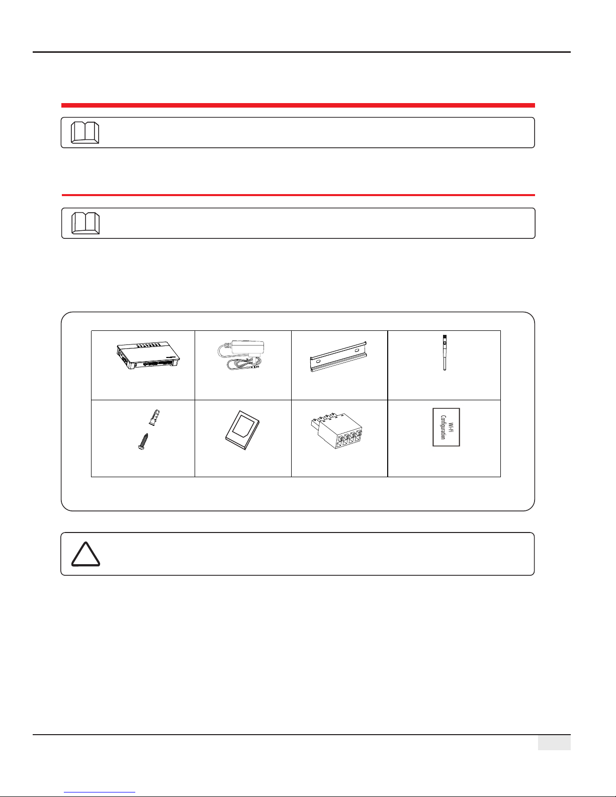
3.1 Packaging Information
EzLogger Pro x1
Power adapter x1
Guide rail x1
Expansion screw x2
User manual x1
.....
..
.
...
.
.
.......
..
.
.
..
.
..
...
Wiring terminal x4
Introduce the packaging information and installation process of EzLogger Pro.
After opening the EzLogger Pro package, please check whether the accessories are
complete and there is any apparent damage. If there is any damage or certain items are
missing, please contact your dealer.
Delivery diagram of accessories:
Introduce the packaged accessories of EzLogger Pro.
Figure 3.1-1 Delivery Diagram of EzLogger Pro Packaged Accessories
Power adapter models will be determined according to the safety
regulations of export destination countries.
Wi-Fi Configuration x 1
(Wi-Fi model only)
(Wi-Fi/GPRS model only)
Antenna x 1
08
3.2 Equipment Installation
3.2.2 Install EzLogger Pro
There are three installation methods for EzLogger Pro, namely, table surface mounting, wall
mounting and rail mounting.
The following points shall be considered when you select the installation location:
1. The ingress protection rating of EzLogger Pro is IP20, so it has no waterproof performance and is
for indoor use only.
2. The installation method and location shall be suitable for the weight and size of EzLogger Pro.
3. The installation location shall be well-ventilated away from direct sunlight, and ensure the
ambient temperature is within the range of -20℃ ~ 60℃.
3.2 Equipment Installation
3.2.1 Choose the installation location
Introduction the installation process of EzLogger Pro.
Please select the table surface mounting method for EzLogger Pro so as not avoid damage
to EzLogger Pro due to falling. Do not put EzLogger Pro in a location where it touches
cables easily so as to avoid signal interruption due to cable touching.
Installation method 2: Wall mounting
Steps:
1. Drill two circular holes in the wall. The distance between the two circular holes is
70mm, the hole diameter is 8mm, and the screw head protrudes 4mm.
2. Hang the wall mounting holes on the back of EzLogger Pro onto the screws.
Installation method 1: T mountingable surface
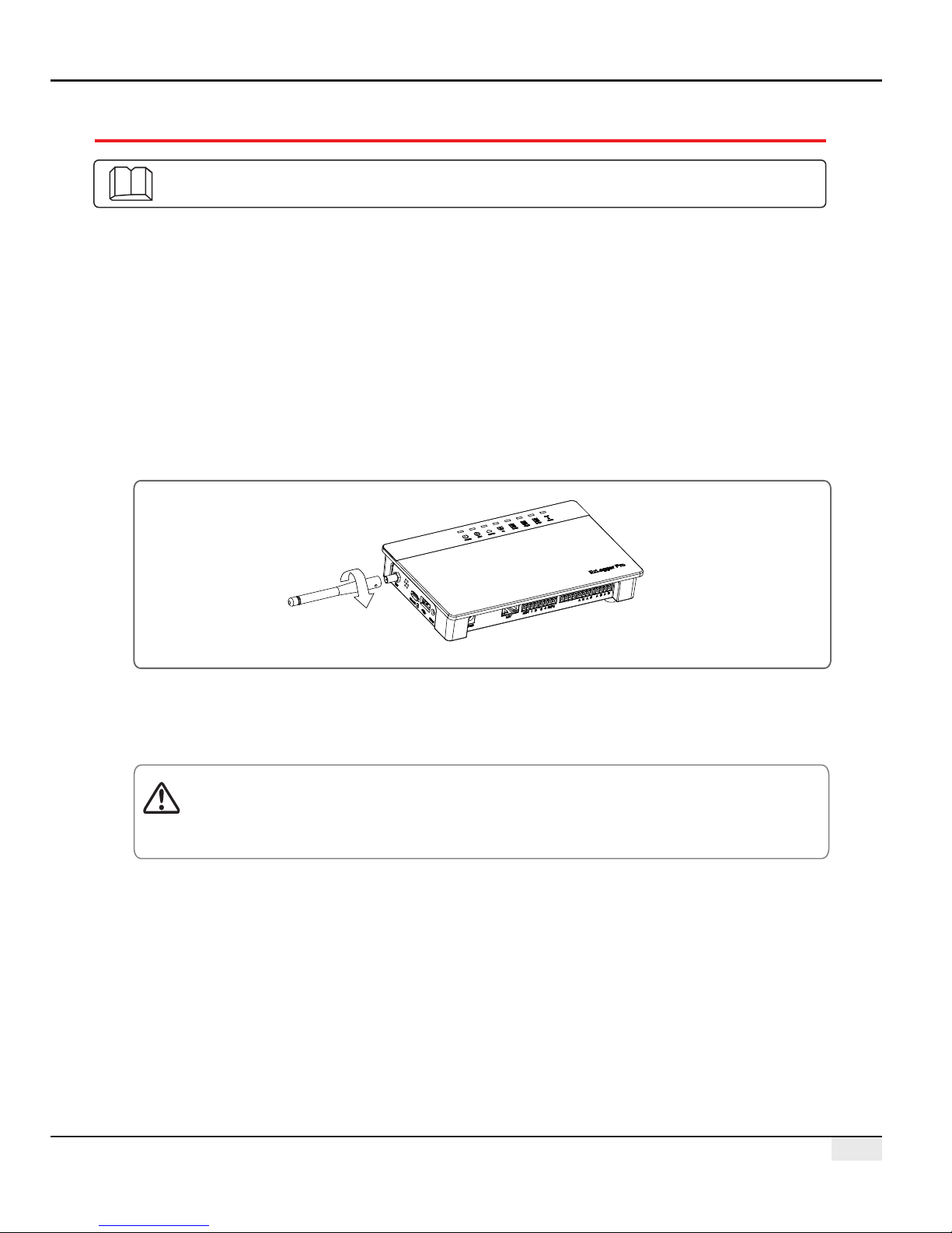
Install the EzLogger Pro ( .antenna to Wi-Fi/GPRS model only)

09
3.2 Equipment Installation
2. Install the guide rail on the wall.
3. Install EzLogger Pro on the guide rail.
Installation method 3: Rail mounting
Steps:
1. Drill two circular holes in the wall, the distance between the two circular holes is 100mm,
the hole diameter is 8mm, and the hole depth is 40mm.
100mm
=8mm
D=40mm
Figure 3.2.2-2 Schematic Diagram of Rail Mounting
Figure 3.2.2-3 Schematic Diagram of Installation of Ezlogger Pro onto Guide Rail
Figure 3.2.2-1 Schematic Diagram of Wall Mounting of EzLogger Pro
70mm
 Loading...