

Page 1

ES Series User Manual
HYBRID PV
INVERTER
350-00035-T0
Page 2

1
Table of Contents
1. Introduction....................................................................................................2
2. Important Safety Warning..............................................................................2
2.1 Symbols................................................................................................3
2.2 Safety....................................................................................................3
3. Installation.....................................................................................................5
3.1 Packing List..........................................................................................5
3.2 Product Overview.................................................................................6
3.3 Selecting The Mounting Location.........................................................6
3.4 Mounting..............................................................................................8
4. Electrical Connection......................................................................................9
4.1 AC Output Connection.........................................................................9
4.2 PV Connection....................................................................................11
4.3 Battery Connection.............................................................................13
4.4 RS485 Communication Connection....................................................15
4.5 WiFi Communication Connection......................................................17
4.6 USB Communication Connection.......................................................17
5. LED Lights Illustration..................................................................................18
6. Error Messages..............................................................................................18
7. Specifications................................................................................................19
8. Certificates....................................................................................................21
Page 3
2
1. Introduction
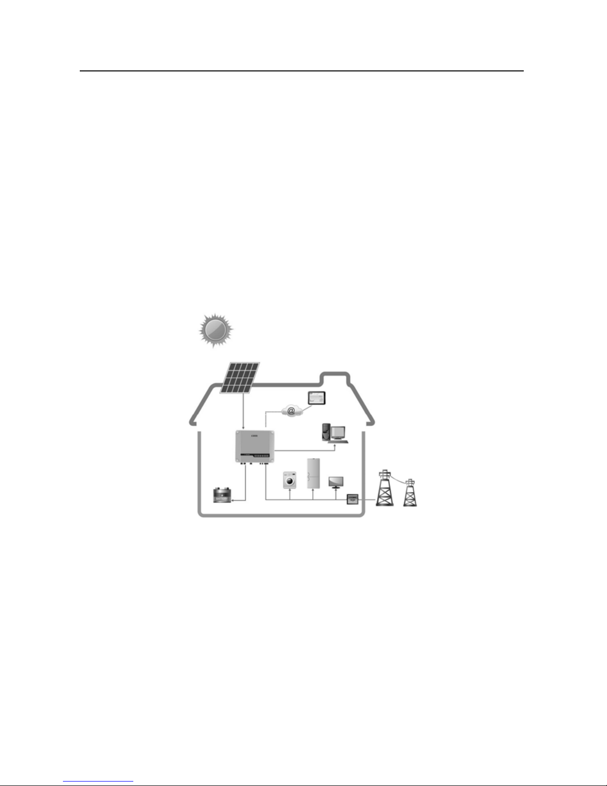
GoodWe ES series inverters (hybrid) are bidirectional which apply to PV system
with battery to store energy.
Energy produced by the PV system is used to optimize self-consumption; excess
energy is used to charge the batteries, and then fed into the public grid when the
PV energy is adequate,
When PV energy output is insufficient to support connected loads, the system
automatically get energy from the batteries if battery capacity is abundant. If the
battery capacity is insufficient to meet own consumption requirements, load get
electricity from the public grid.
GoodWe ES series inverter is design for both indoor and outdoor use.
Figure 1-1 Basic hybrid PV system overview
2. Important Safety Warning
Before using the inverter, please read all instructions and cautionary markings on
the unit and this manual. Store the manual where it can be accessed easily.
The ES series inverter of Jiangsu GoodWe Power Supply Technology Co. Ltd.
(hereinafter referred to as GoodWe) strictly conforms to related safety rules in
design and test.
Safety regulations relevant to the location shall be followed during installation,
Page 4
operatio
Improp
e
propert
y
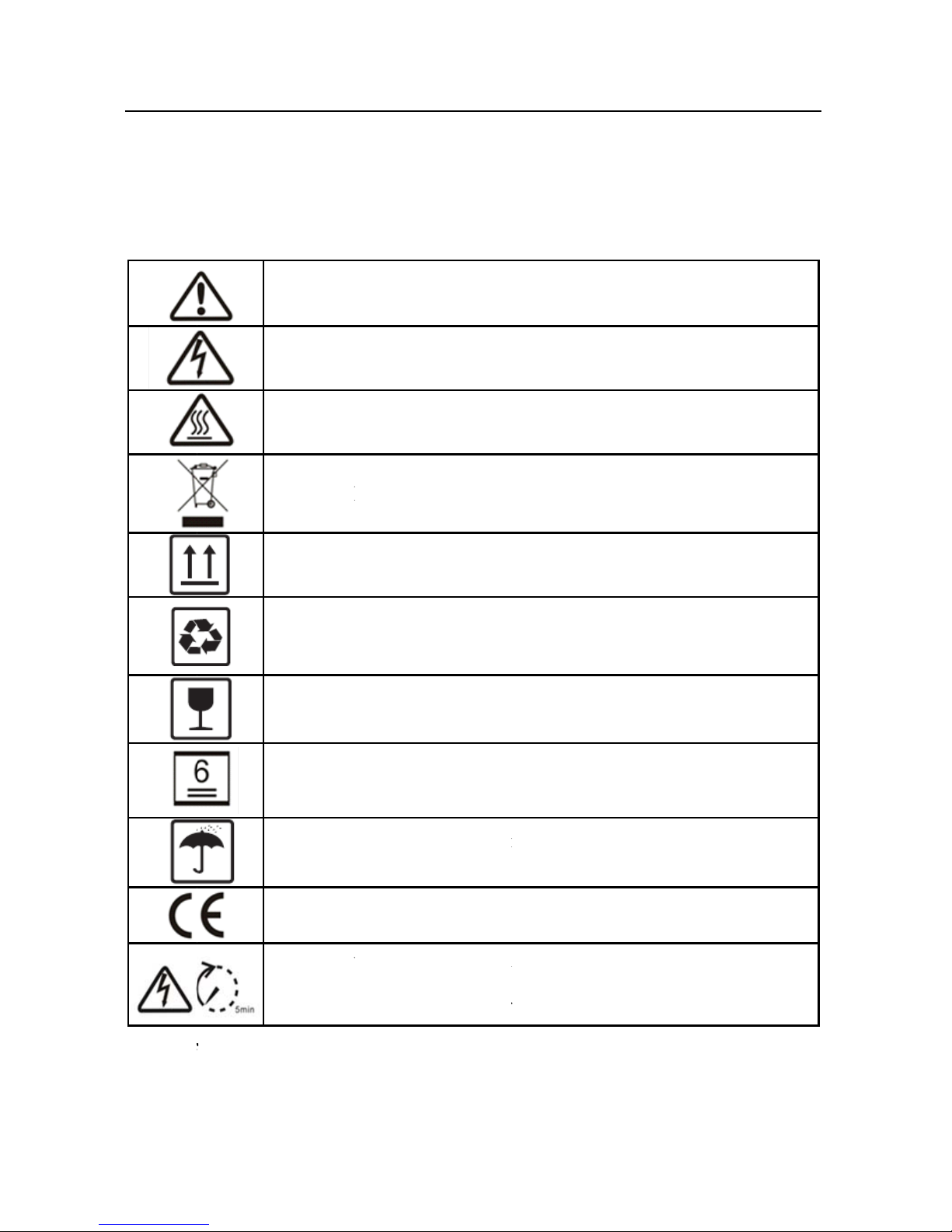
2.1 S
ym
2.2 Sa
f
z Ins
n and maintenanc
e
r operation may h
a
.
bols
Caution!
manual
m
Danger o
f
Danger o
f
Product s
h
This side
and store
d
Compon
e
Fragile; t
h
never be
t
No more
other.
Keep dr
y
excessiv
e
CE Mark
Residual
v
maintena
n
capacitor
ety
tallation, mainten
a
.
ve a risk of electri
c
- Failure to obs
e
ay result in injury
.
high voltage and
hot surface!
ould not be dispo
up; the package
m
in such a way th
a
nts of the product
e package/produ
c
ipped over or slun
than 6 identical
p
; the package/p
r
humidity and mu
s
oltage exists in t
h
ce, at least 5
m
in the inverter to
fu
nce and connectio
n
shock or damage
rve a warning i
n
electric shock!
sed as household
w
ust always be tran
s
t the arrows alway
can be recycled.
t should be handl
e
g.
ackages may be
s
oduct must be
t be stored under
c
e inverter; before
c
inutes must be
a
lly discharge.
of inverters mus
t
3
to equipment and
dicated in this
aste.
ported, handled
s point upwards.
d carefully and
tacked on each
protected from
over.
ommencing any
llowed for the
be performed by
Page 5

4
qualified personnel, in compliance with local electrical standards,
regulations and the requirements of local power authorities and/or
companies.
z To avoid electric shock, DC input and AC output of the inverter must be
terminated at least 5 minutes before performing any installation or
maintenance.
z The temperature of some parts of the inverter may exceed 60℃ during
operation. To avoid being burnt, do not touch the inverter during operation.
Let it cool before touching it.
z Ensure children are kept away from inverters.
z Do not open the front cover of the inverter. Apart from performing work at
the wiring terminal (as instructed in this manual), touching or changing
components without authorization may cause injury to people, damage to
inverters and annulment of the warranty.
z Static electricity may damage electronic components. Appropriate method
must be adopted to prevent such damage to the inverter; otherwise the
inverter may be damaged and the warranty annulled.
z Ensure the output voltage of the proposed PV array is lower than the
maximum rated input voltage of the inverter; otherwise the inverter may be
damaged and the warranty annulled.
z PV modules should have an IEC61730 classA rating. If the maximum AC
mains operating voltage is higher than the PV array maximum system
voltage, PV modules should have a maximum system voltage rating based
upon the AC mains voltage.
z If the equipment is used in a manner not specified by the manufacturer, the
protection provided by the equipment may be impaired.
z Completely isolate the inverter should : Switch off the DC switch,
disconnect the PV terminal, disconnect the battery terminal, and disconnect
the AC terminal.
z Completely isolate the inverter before maintaining. Not to enter other areas
of the inverter when maintaining!
z Prohibit to insert or pull the AC and DC terminals when the inverter is
running
z Electrical Installation & Maintenance shall be conducted by licensed
Page 6
5
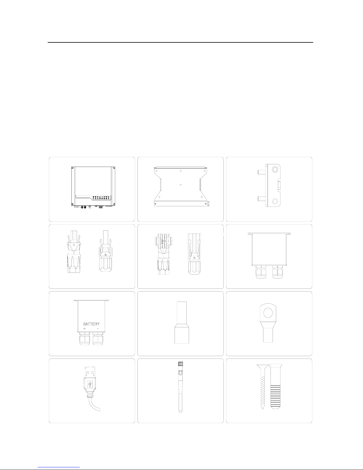
USB data cable x1
battery terminal x2AC terminal x6battery cover x1
AC cover x1
negative PV plug x2positive PV plug x2
lock plate x1wall-mounted bracket x1inverter x1
or or
antenna x1
expansion bolt x6
electrician .
z Machine shipping to Australia shall comply with Australia National Wiring
Rules.
3. Installation
3.1 Packing List
Before installation, please inspect the unit. Be sure that nothing inside the
package is damaged. You should have received the following items inside of
package:
Page 7
6
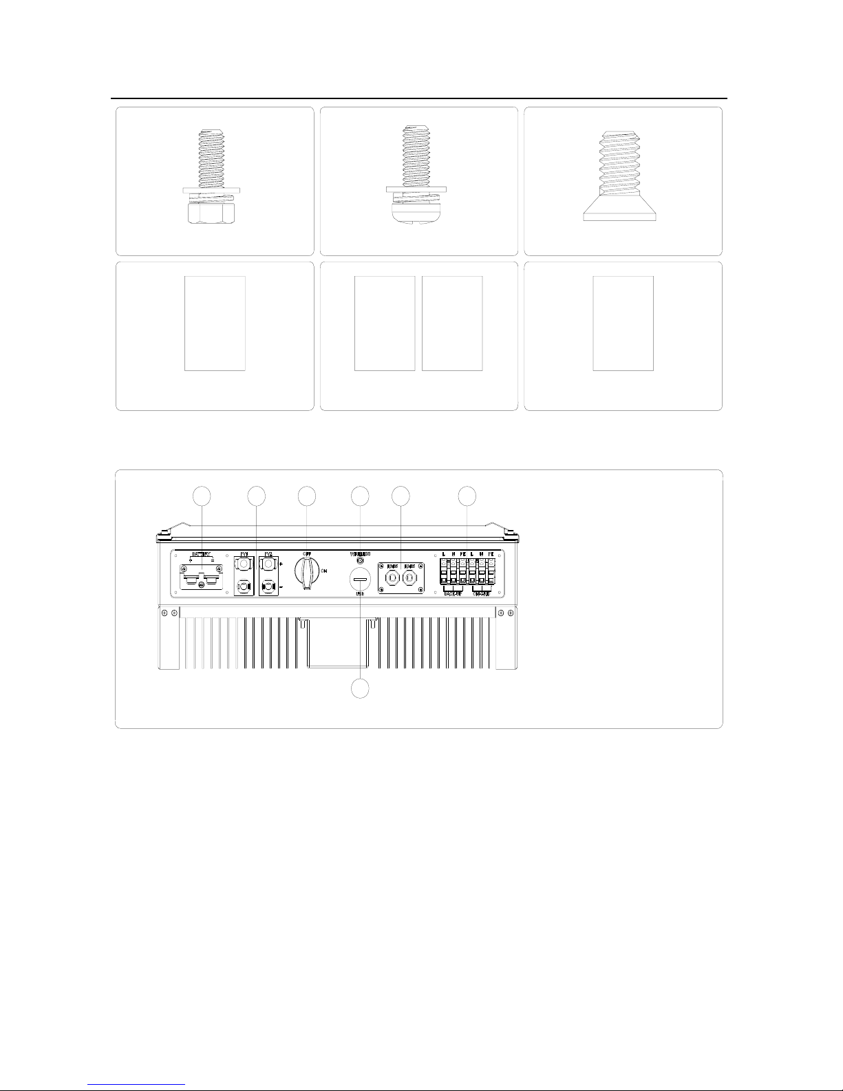
user manual
fast
installation
WiFi fast installation x1user manual x1
flat head screw x5pan head screw x8hexagon head screw x2
warranty
Card
warranty card x1
WiFi f ast
installation
fast installation x1
3.2 Product Overview
Figure 3.2-1
12346 7
5
1. Battery input ports
2. PV input ports
3. DC switch (optional)
4. Wireless port
5. USB port
6. RS485 ports
7. AC output ports
3.3 Selecting The Mounting Location
Mounting location should be selected based on the following aspects:
z The installation method and mounting location must be suitable for the
inverter's weight and dimensions.
z Mount on a solid surface.
z Select a well ventilated place sheltered from direct sun radiation.
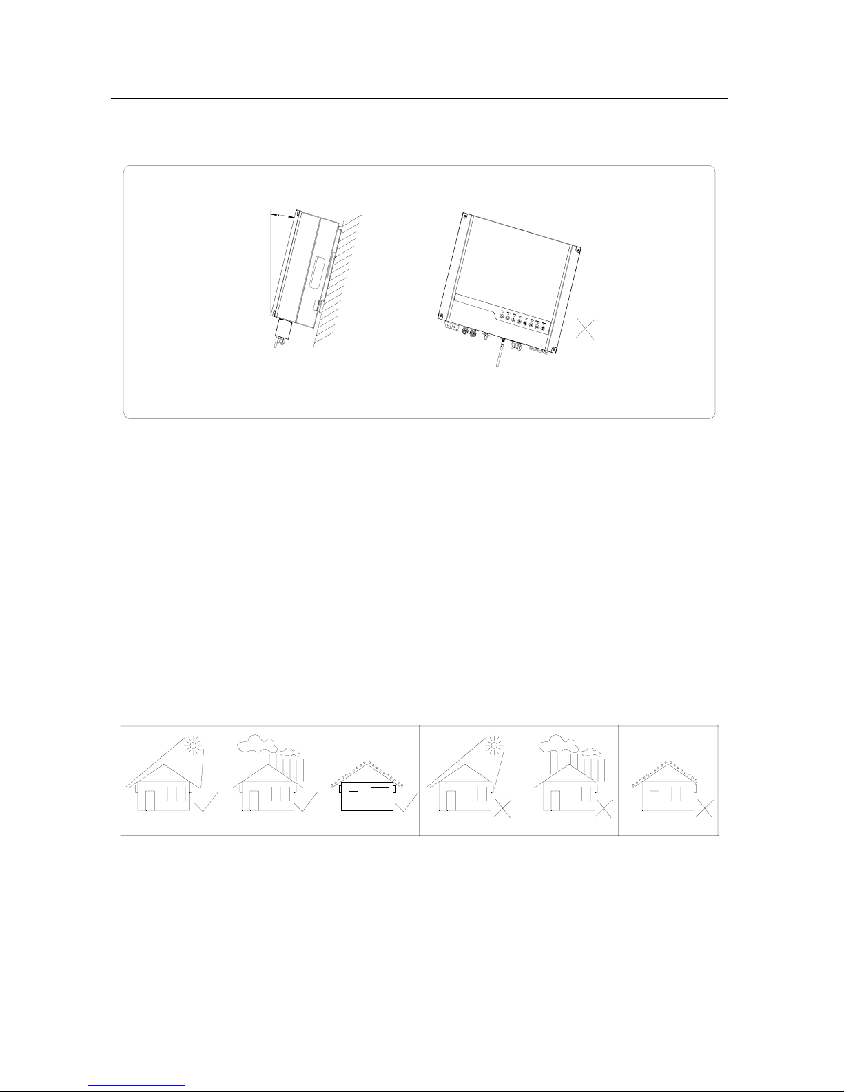
z Install vertically or tilted backward by max 15°. The device cannot be
Page 8
7
installed with a sideways tilt. The connection area must point downwards.
Refer to Figure 3.3-1.
1
5
°
Figure 3.3-1
z In order to achieve optimal performance, the ambient temperature should
be lower than 45 °C.
z For the convenience of checking the LED lights and possible maintenance
activities, please install the inverter at eye level.
z Inverters should NOT be installed near inflammable and explosive items.
Any strong electro-magnetic equipment should be kept away from
installation site.
z Product label and warning symbol shall be clear to read after installation.
z Please avoiding direct sunlight, rain exposure, snow lay up when installing.
direct sunlight
rain exposure snow lay up
Figure 3.3-2
no direct sunlight
norain exposure no snow lay up
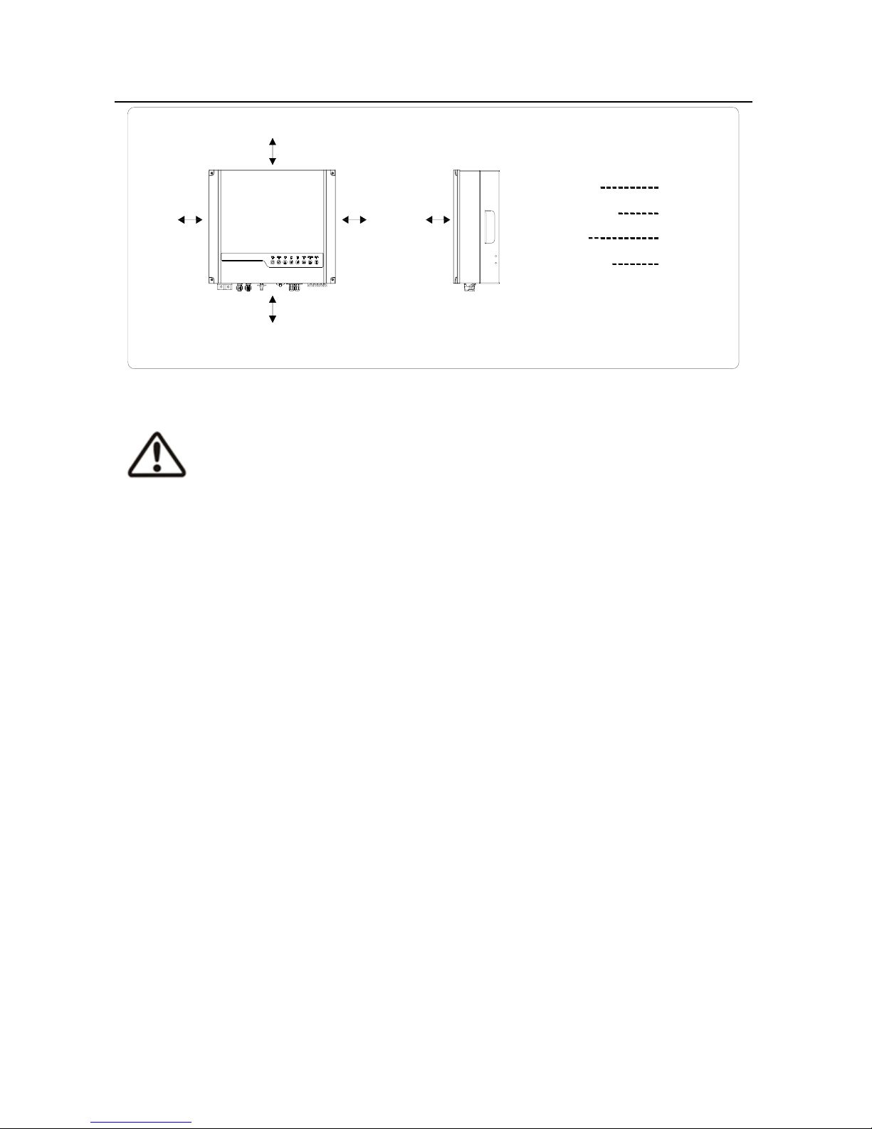
z In consideration of heat dissipation and convenient dismantlement, the
minimum clearances around the inverter should be no less than the following
value:
Page 9
8
500mm 500mm
300mm
300mm
500mm
upward
300mm
downward
500mm
front
300mm
both sides
500mm
Figure 3.3-3
3.4 Mounting
Remember that this inverter is heavy! Please be carefully when lifting out from
the package.
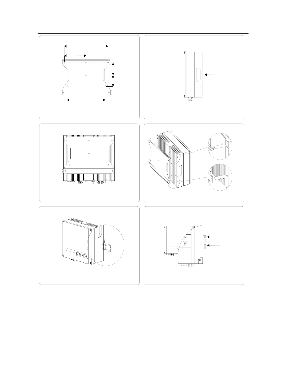
1. Use the wall-mounted bracket as a template and drill 6 holes on
the wall, 10 mm in diameter and 80 mm deep. Refer to Figure
3.4-1.
2. Fix the wall mounting bracket on the wall with six expansion bolts
in accessory bag.
3. Carry the inverter by holding the handles. Refer to Figure 3.4-2.
4. Place the inverter on the wall-mounted bracket. Refer to Figure
3.4-3、 Figure 3.4-4.
5. Fix the inverter with the lock plate in accessory bag. Refer to
Figure 3.4-5.
6. Use flat head screw in accessory bag and a padlock to fix the lock
plate on the wall-mounted bracket. Refer to Figure 3.4-6.
Page 10
9
457mm
229mm
117mm
105mm
400mm
Figure 3.4-1
Figure 3.4-2
Figure 3.4-3 Figure 3.4-4
a
b
detail a
detail b
Figure 3.4-5 Figure 3.4-6
flat head screw
paklock
4. Electrical Connection
4.1 AC Output Connection
Before connecting to Grid and Load, please install a separate AC breaker
(250VAC/30A)between inverter and Grid. This will ensure the inverter can be
Page 11
10
securely disconnected during maintenance.
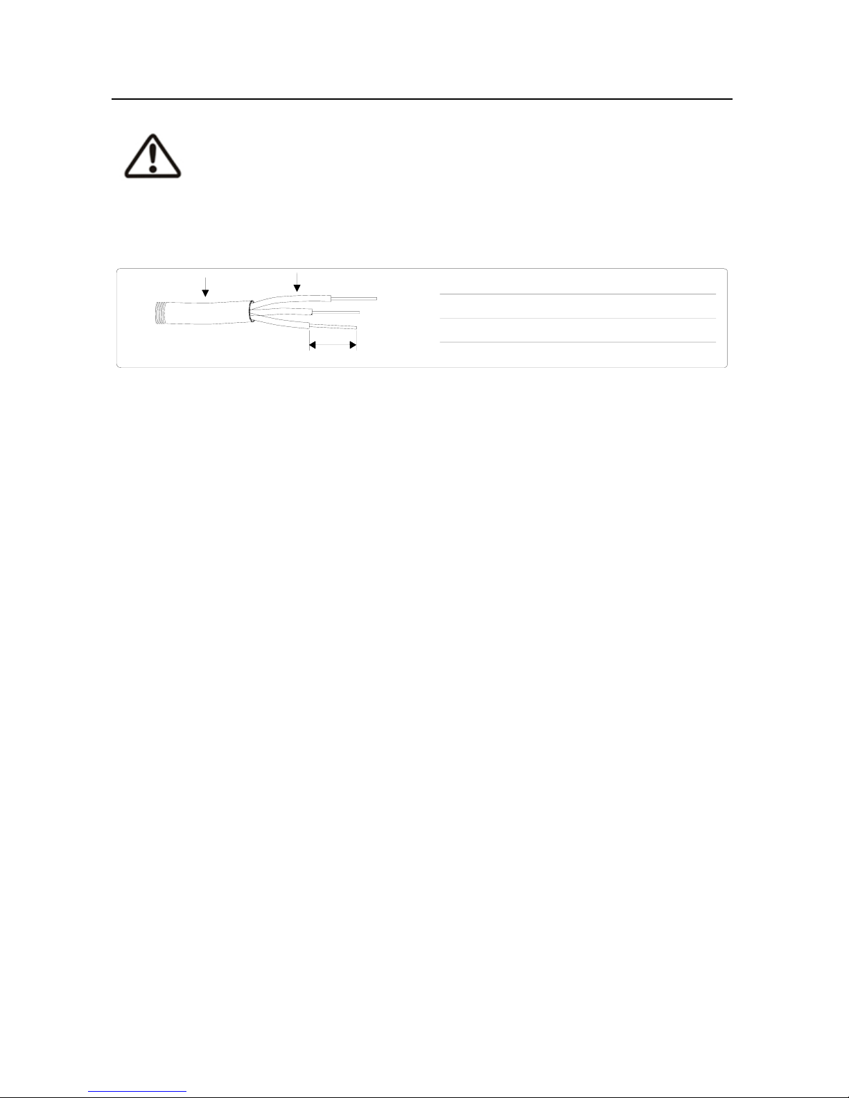
It's very important for system safety and efficient operation to use appropriate
cable for AC connection. To reduce risk of injury, please use the proper
recommended cable size. Refer to Figure 4.1-1.
Description Size
A External diameter of the wire
10mm-12mm
B Sectional area of conducting materials
3mm -4mm
C Length of bare wire
Approx.10mm
22
Figure 4.1-1
A
B
C
Please follow below steps to implement AC connection:
1. Check the grid voltage and frequency at the connection point of
the inverter. It should meet GoodWe product Spec.
2. Measure the impedance between neutral cable and earth cable,
make sure it is not excess than 10ohm.
3. Disconnect AC breaker between inverter and Grid.
4. Disconnect screw cap from insulator.
5. Disconnect waterproof ring from insulator.
6. Put the cable through the components in this order: screw cap,
waterproof ring, insulator, AC cover and AC terminal. Refer to
Figure 4.1-2.
7. Compress the terminal head by professional tool and screw down
screw cap slight. Refer to Figure 4.1-3、 Figure 4.1-4.
8. Insert AC terminals into the corresponding holes and fasten them
by screwdriver, then fasten AC cover with pan head screws in
accessory bag. Refer to Figure 4.1-5、 Figure 4.1-6 、 Figure 4.1-7.
9. Screw down screw cap again.
Page 12
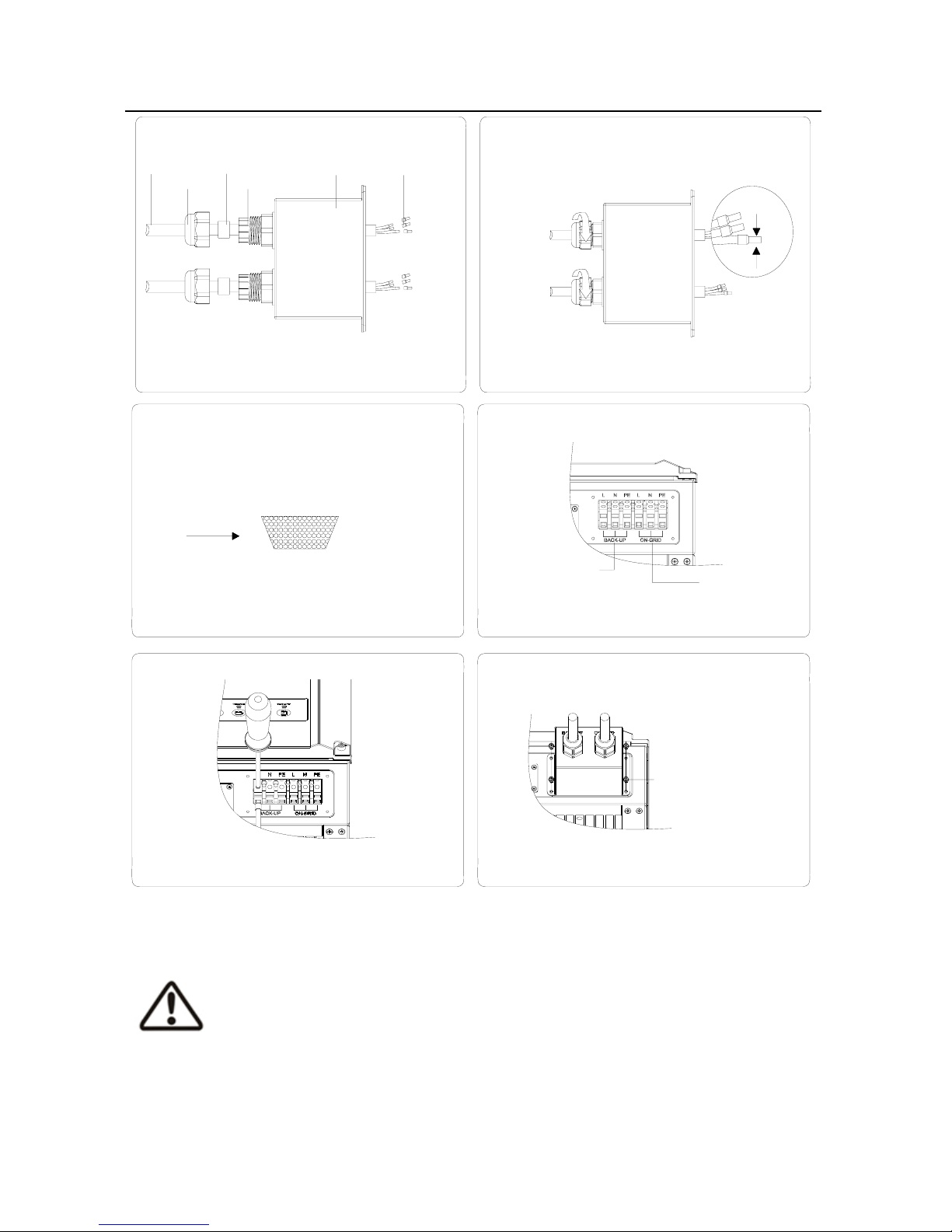
11
cable
Figure 4.1-2 Figure 4.1-3
waterproof ring
AC cover
AC terminal
screw cap
insulator
crimp
Figure 4.1-4 Figure 4.1-5
cable core section after crimp
Figure 4.1-6 Figure 4.1-7
L----line N----neutral PE----earth
back-up
terminal
grid terminal
pan head screw
4.2 PV Connection
z Before connecting the PV panels, ensure the plug connectors have the correct
polarity. Incorrect polarity could permanently damage the inverter.
Page 13
12
z Check the short-circuit current of the PV string. The total short-circuit current
must not exceed the inverter’s maximum PV current.
z PV array should not be connected to the grounding conductor.
z Must be use PV plugs in accessory bag.
z The minimum array insulation resistance to ground that system designer or
installer must meet when selecting the PV panel and system design, based on
the minimum value that the design of the PV functional grounding in the
inverter was based on. The minimum value of the total resistance 19.33kΩ
that the system must meet. There is a risk of shock hazard if the total
minimum resistance requirement is not met.
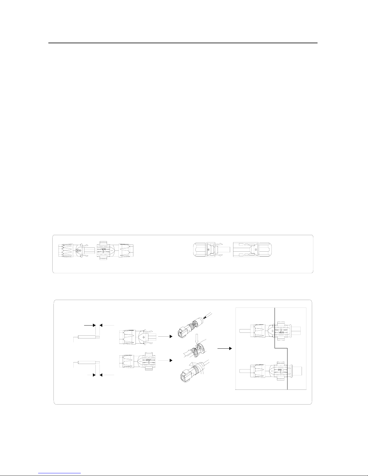
There are two types of PV plugs----sunclix series and MC4 series. Refer to
Figure 4.2-1.
Figure 4.2-1
sunclix series MC4 series
The installation method of sunclix series Refer to Figure 4.2-2.
inverter side
Figure 4.2-2
7mm
7mm
2.5~4mm
2.5~4mm
2
2
The installation method of MC4 series Refer to Figure 4.2-3.
Page 14
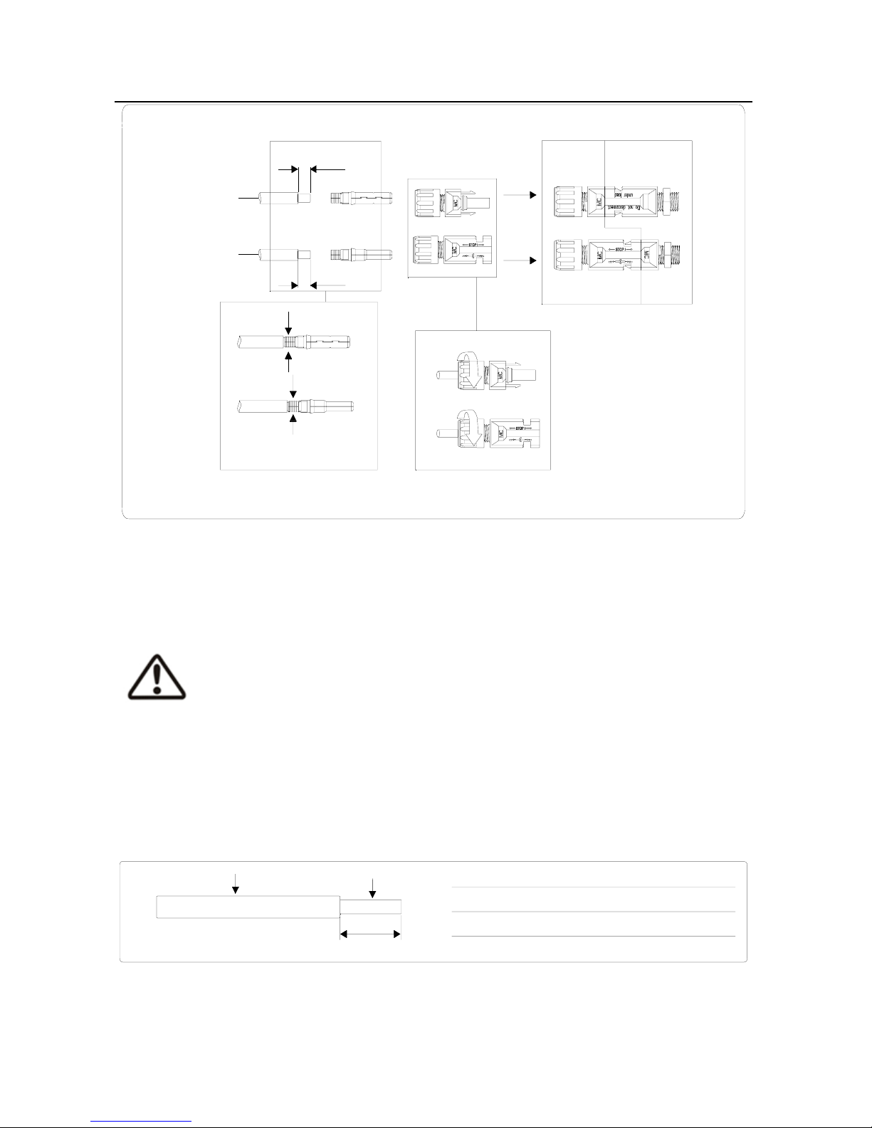
13
inverter side
compress by
professional tool
2.5~4mm
2
2.5~4mm
2
7mm
7mm
Figure 4.2-3
4.3 Battery Connection
Before connecting to battery, please install a separate DC breaker (60A for
GW3648D-ES and 120A for GW5048D-ES) between inverter and battery. This
will ensure the inverter can be securely disconnected during maintenance.
z Be aware of electric shock and chemical hazards!
z It is a normal phenomenon that electric arc occurs when connecting battery
to the inverter without use a DC breaker.
z It's very important for system safety and efficient operation to use
appropriate cable for battery connection. To reduce risk of injury, please use
the proper recommended cable size. Refer to Figure 4.3-1.
Description Size
A External diameter of the wire
10mm-12mm
B Sectional area of conducting materials
20mm -25mm
C Length of bare wire
Approx.10mm
22
Figure 4.3-1
A
B
C
z Before connecting to battery, please install a separate DC breaker (60A for
GW3648D-ES and 120A for GW5048D-ES) between inverter and battery.
Page 15

14
This will ensure the inverter can be securely disconnected during
maintenance.
z Suggestion: The battery be installed indoor, details please refer to battery
manufacture’s user manual.
z Suggestion: The battery be installed with a distance to each other, details
please refer to battery manufacture’s user manual.
z About the number of cells used, it will be dicided by customer’s choice, the
choice comply with the followed requirement: the total voltage is 48V, the
max capacity is 500Ah.
Please follow below steps to implement battery connection:
1. Check the nominal voltage of batteries. The nominal input voltage
should meet GoodWe product Spec.
2. Disconnect DC breaker between inverter and battery.
3. Disconnect screw cap from insulator.
4. Disconnect waterproof ring from insulator.
5. Put the cable through the components in this order: screw cap,
waterproof ring, insulator, battery cover and battery terminal.
Refer to Figure 4.3-2.
6. Compress the terminal head by professional tool and screw down
screw cap slight. Refer to Figure 4.3-3、 Figure 4.3-4.
7. Put battery terminals into the corresponding holes and fasten them
by screwdriver and spanner, then fasten battery cover with pan
head screws in accessory bag. Refer to Figure 4.3-5、 Figure 4.3-6 、
Figure 4.3-7.
8. Screw down screw cap again.
Page 16
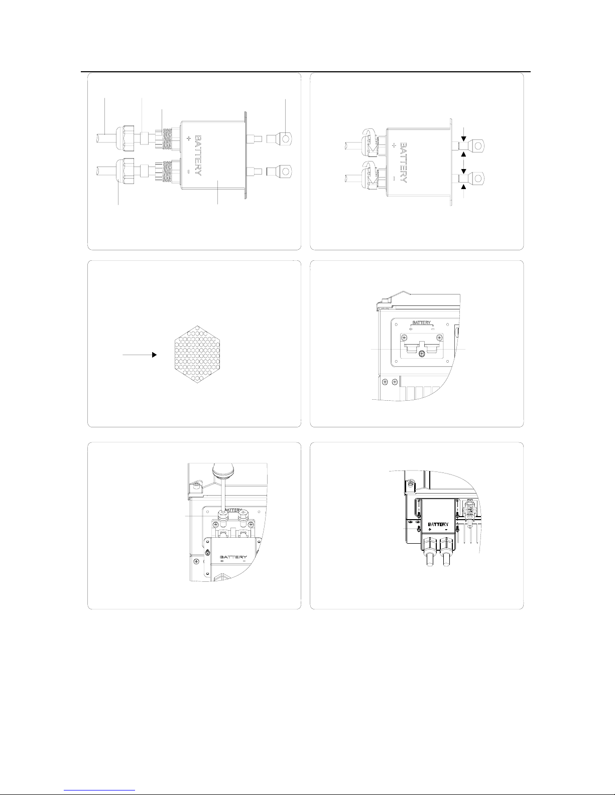
15
cable
Figure 4.3-2 Figure 4.3-3
waterproof ring
battery cover
battery terminal
screw cap
insulator
crimp
Figure 4.3-4 Figure 4.3-5
cable core section after crimp
+ ----red cable
- ----black cable
positive
terminal
negative
terminal
Figure 4.3-6 Figure 4.3-7
hexagon head screw
pan head screw
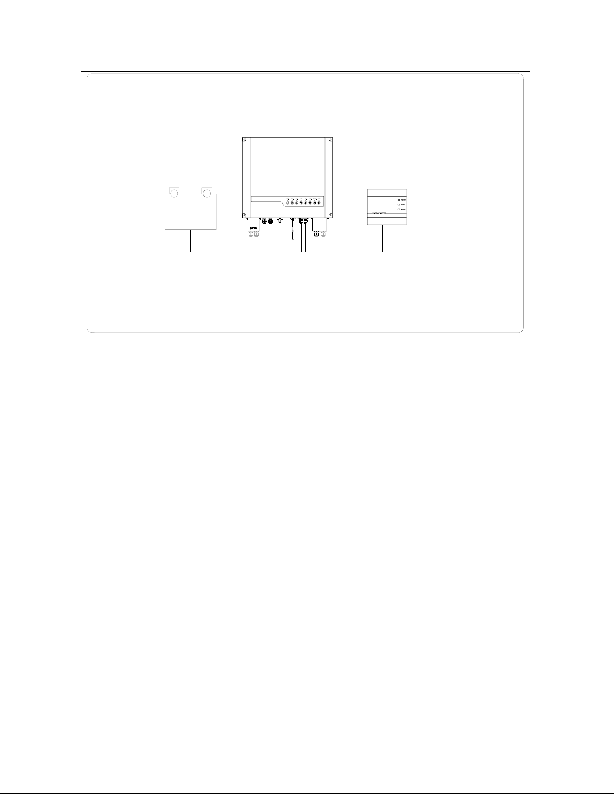
4.4 RS485 Communication Connection
An RS485 interface is used for Li-ion and EzMeter communication. The cable
length should not exceed 800m.The connection method of RS485 refer to Figure
4.4-1.
Page 17
16
+
-
battery
Figure 4.4-1
EzMeter
RS485RS485
(Li-Ion)
EzMeter is a equipment for energy measurement developed by GoodWe
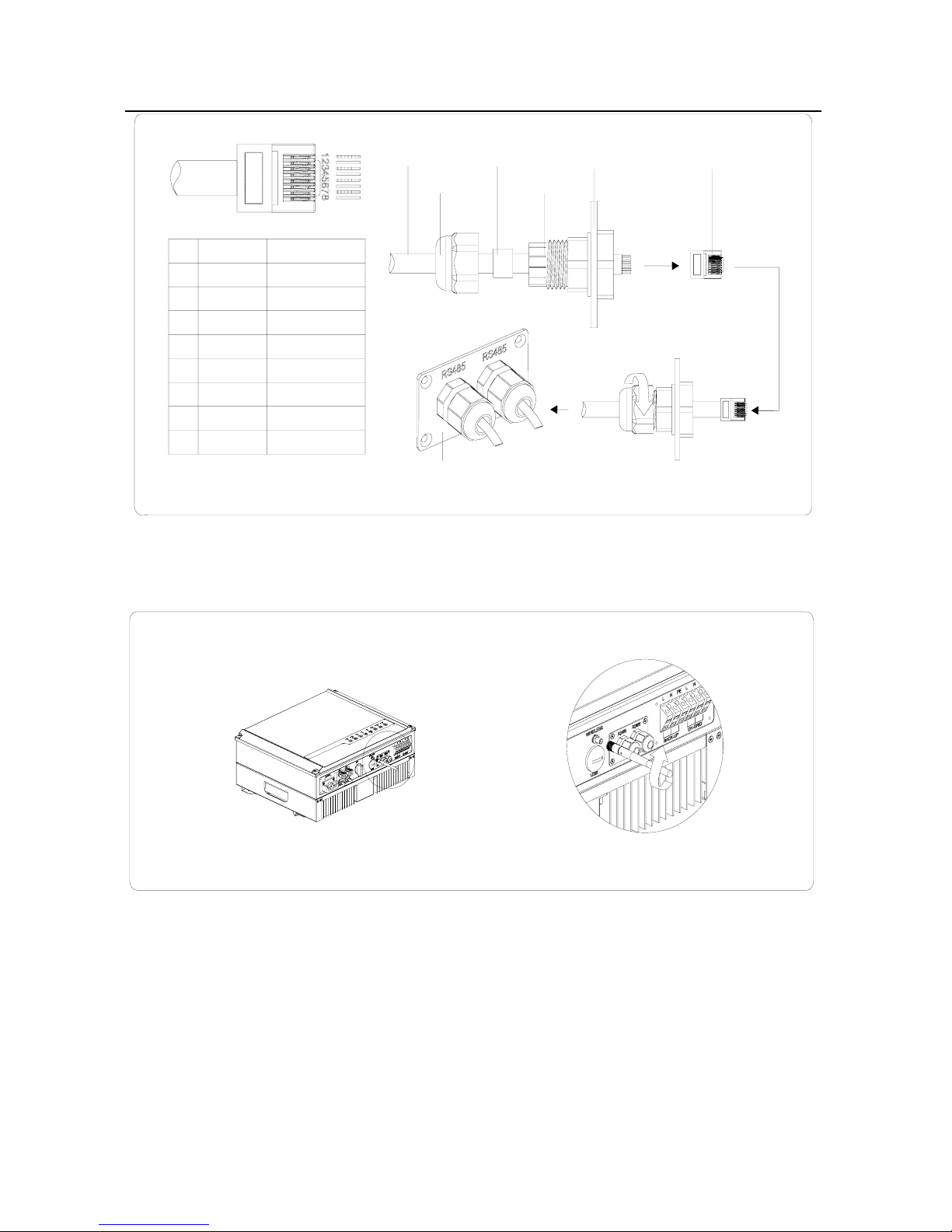
Please follow below steps to implement RS485 connection:
1. Remove RS485 waterproof assembly from inverter.
2. Disconnect screw cap from insulator.
3. Disconnect waterproof ring from insulator.
4. Put the cable through the components in this order: screw cap,
waterproof ring, insulator, RS485 cover. Refer to Figure 4.4-2.
5. Put cable cores insert into the corresponding slots and compress
the crystal head by professional tool, then screw down screw cap
slight. Refer to Figure 4.4-2.
6. Put crystal head insert into the corresponding inner slots of
inverter.
7. Fasten RS485 waterproof assembly to inverter.
8. Screw down screw cap again.
Page 18
17
cable waterproof ring
RS485 cover
crystal head
screw cap
insulator
Figure 4.4-2
PIN
1
2
3
4
5
6
7
8
RESERVED
RX_RS485B
RX_RS485A
TX_RS485B
TX_RS485A
FunctionColor
orange/white
orange
green/white
blue
blue/white
green
brown/white
brown
RS485 waterproof assembly
RESERVED
RESERVED
RESERVED
4.5 WiFi Communication Connection
Install the antenna to inverter. Refer to Figure 4.5-1.
Figure 4.5-1
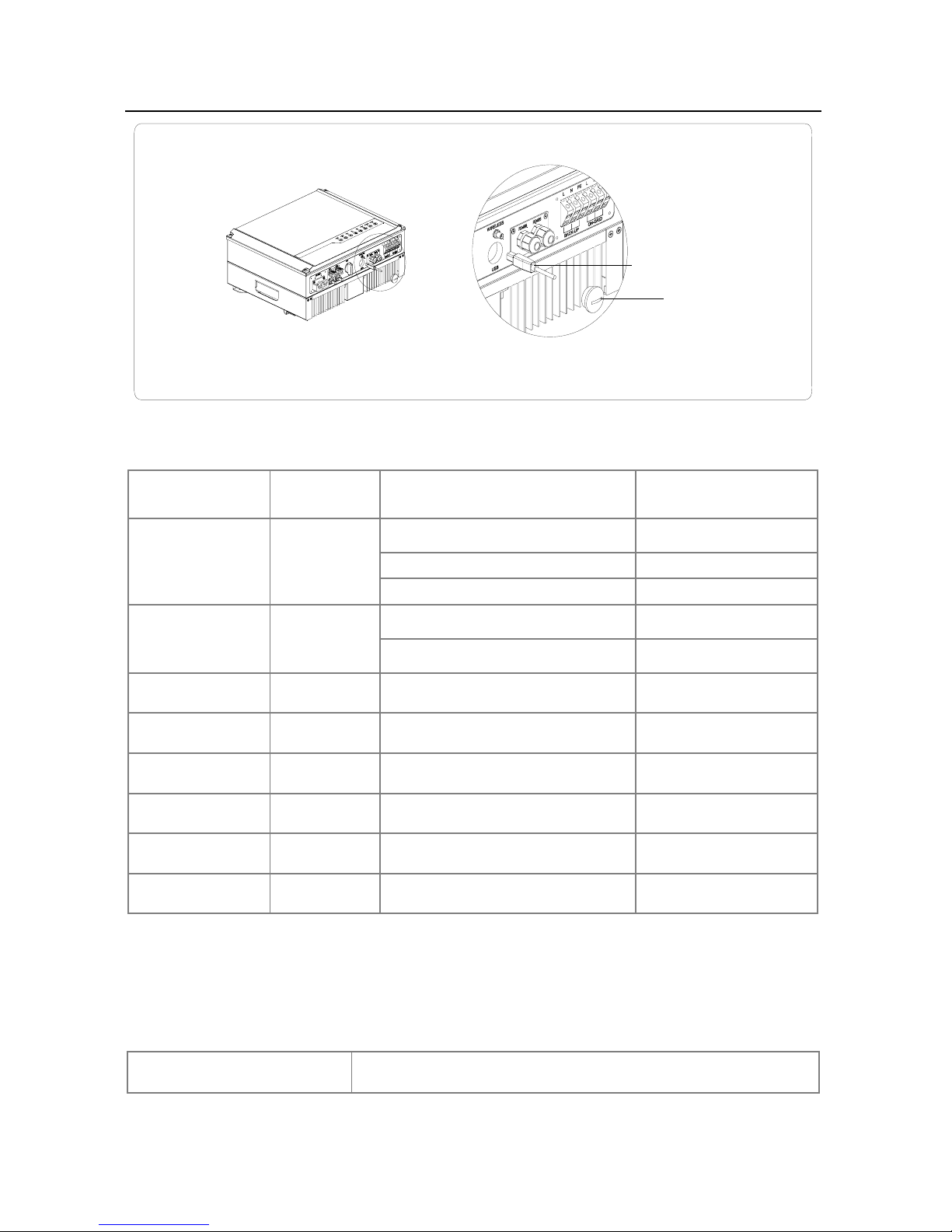
4.6 USB Communication Connection
The USB communication is used for firmware update only!
Please follow below Figure 4.6-1 to implement USB connection:
Page 19
18
Figure 4.6-1
open USB cover
insert USB data cable
5. LED Lights Illustration
Inverter Status LED Color Inverter Status Note LED Display Status
Wifi Yellow
WIFI link NG
Blink 1s on 1s off
WIFI link OK,Internet NG Blink 2.5s on 2.5s off
WIFI link OK,Internet OK Constant on
Normal Green
Normal
Constant on
Checking
Blink 0.5s on 0.5soff
Fault Red
Fault
Constant on
Sale Green
Generate to grid
Constant on
Buy Yellow
Consumption from grid
Constant on
Charge Green
Battery Charging
Constant on
Discharge Green
Battery Discharging
Constant on
Battery Low Red
Battery Low / Bad / Disconnect Blink 0.5s on 0.5soff
6. Error Messages
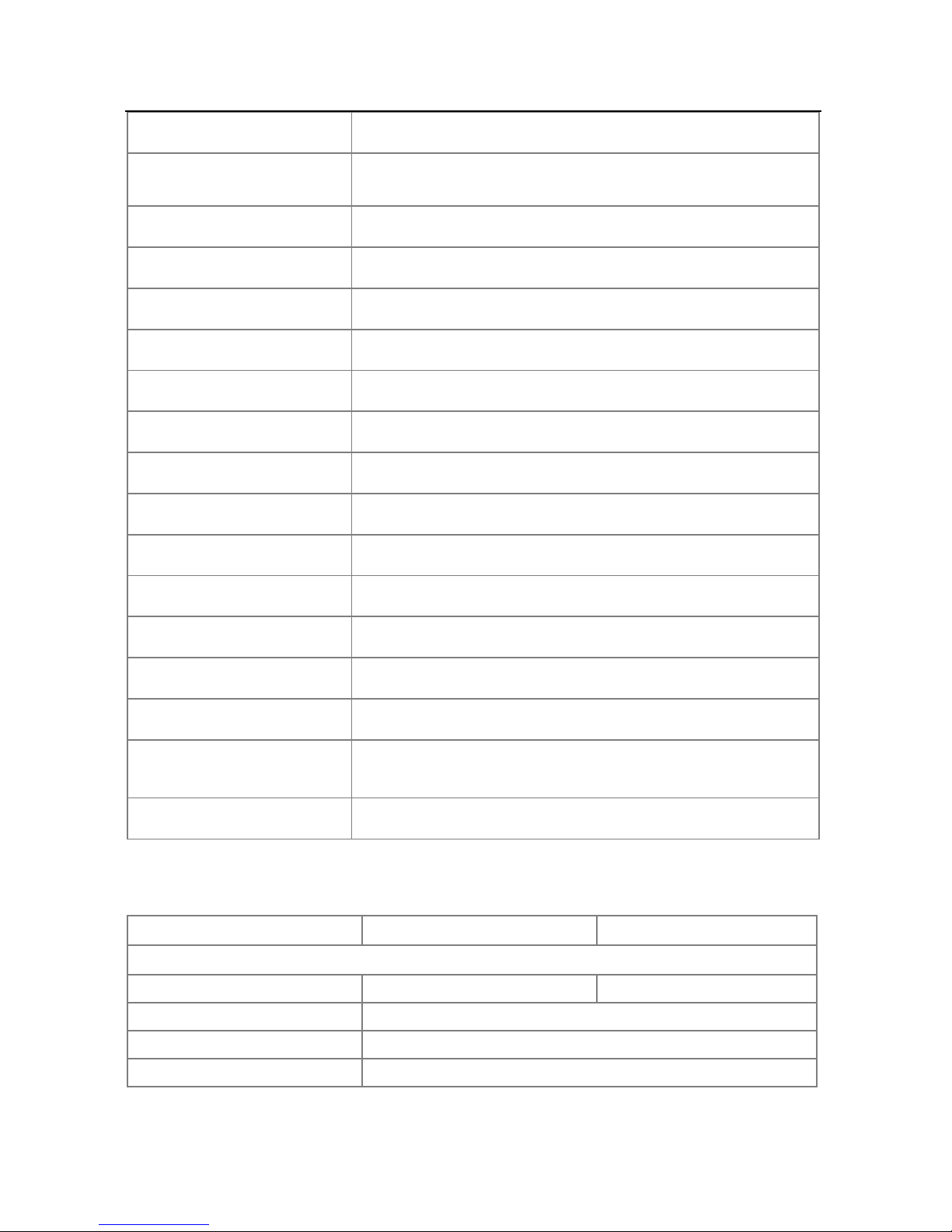
An error message will be displayed on the Monitor if a fault occurs.
Table 6-1 Description of Error Message
Error message Description
Page 20
19
Utility Loss Grid disconnected
Fac Failure Grid frequency no longer within permissible range
Consistent Failure Machine parameter consistent fault
Device Failure Device internal fault
PV Over Voltage Overvoltage at DC input
Over Temperature Overtemperature on the case
Isolation Failure Ground insulation impedance is too low
Ground I Failure Overhigh ground leakage current
Relay-Check Failure Relay self-checking failure
DC Injection High Overhigh DC injection
EEPROM R/W Failure Memory chip failure
SCI Failure Internal communication failure
DC Bus High Overhigh BUS voltage
Ref 2.5V Failure 2.5V reference voltage failure
AC HCT Failure Output current sensor failure
GFCI Failure Detection circuit of ground leakage current failure
Vac Failure Grid voltage no longer within permissible range
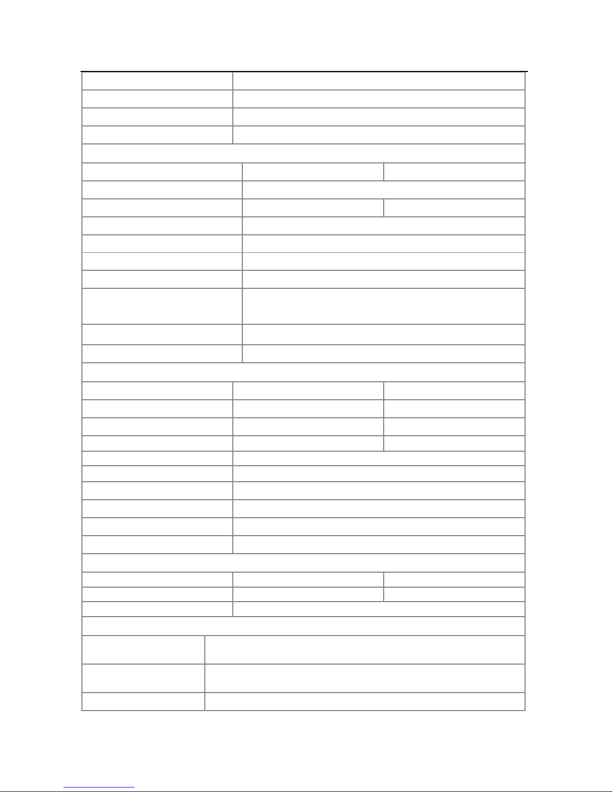
7. Specifications
Model name GW5048D-ES GW3648D-ES
Solar
Max. DC power(W) 5400 4200
Max. DC voltage (V) 580
MPPT voltage range (V) 125~550
Starting voltage (V) 125
Page 21
20
Max. DC current (A) 15/15
No. of DC connectors 2
No. of MPPTs 2(can parallel)
DC connector SUNCLIX / MC4 (Optional)
Battery
Battery Type
Lead-acid or Li-Ion Lead-acid or Li-Ion
Battery voltage range (Vdc)
40-60
MAX Discharge power (W)
4600 2300
Charge current (A)
5-50 A continuous, programmable
Battery capacity (Ah)
100~500Ah(depending requirement)
Charging curve
3-stage adaptive with maintenance
Charging voltage
57V
Battery temperature
compensation
included(Li-Ion)
Battery voltage sense
integrated
Current shunt integrated
AC Output Data
Norminal AC power(W)
4600 3600
Max. AC power(W) 4600 3600
Peak power(Back-up)(W) 1.5x Pnom, 10sec 1.5x Pnom, 10sec
Max. AC current(A)
20 16
Norminal AC output 50/60Hz; 230Vac
AC output range 45~55Hz/55~65Hz; 180~270Vac
AC output (Back-up) 230Vac ±2%, 50Hz ±0.2%, THDv<3%(linear load)
THDi
<1.5%
Power factor 0.9 leading~0.9 lagging
Grid connection Single phase
Efficiency
Max. efficiency 97.6% 97.6%
Euro efficiency 97.0% 97.0%
MPPT adaptation efficiency >99.5%
Protection
Residual current
monitoring unit Integrated
Anti-islanding
protection Integrated
DC switch(PV) Integrated
Page 22
21
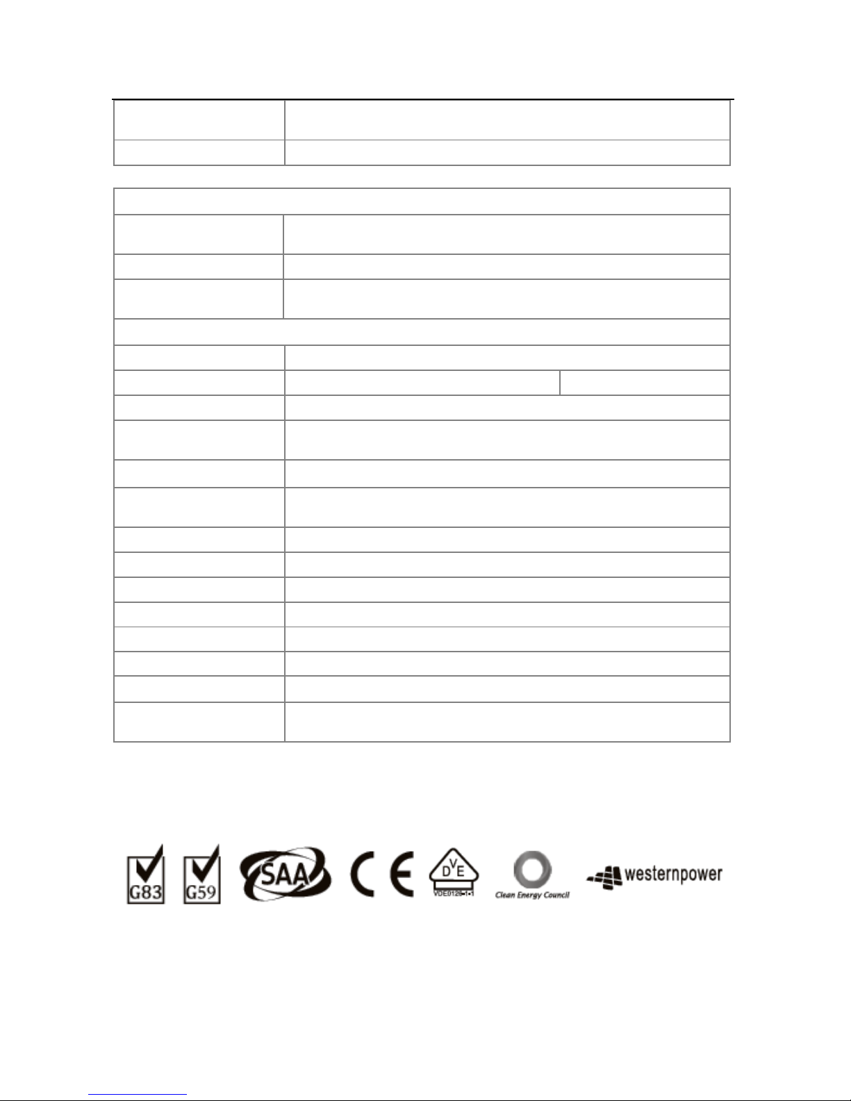
AC over current
protection Integrated
Insulation monitoring Integrated
Certifications&Standards
Grid regulation
VDE4105, VDE 0126-1-1+A1, G83/2, G59/2, AS4777.2/.3,
IEC62109-2
Safety IEC62109-1&-2, AS3100, IEC62040-1
EMC
EN61000-6-1, EN61000-6-2, EN61000-6-3, EN61000-6-4,
EN61000-3-11, EN61000-3-12
General Data
Dimensions (WxHxD) 516*440*184mm
Weight (kg)
30 28
Mounting Wall bracket
Ambient temperature
range
-20~60°C(>45°C derating)
Relative humidity 0~95%
Max. operating
altitude 2000m
Protection degree IP65
Topology Transformerless
Standby losses(W) <8
Cooling Nature convection
Noise emision(dB) <25
Display LED light & APP
Communication
USB2.0; RS485;WIFI;CAN
Standard
warranty(years) 5/10/15/20/25( optional)
8. Certificates
Page 23

GoodWe (Europe)
Mürwikerstr. 59
24943 Flensburg Germany
T: 0049 461 5897 0235
F: 0049 461 5897 0235
www.goodwe.de
GoodWe (Australia)
74 Tarana Avenue,
Glenroy VIC 3046, Australia
T: +61 3 9972 9938
www.goodwe.de
GoodWe (UK)
93 Caversham Place
Sutton Coldfield B73 6HW
www.goodwe.com.cn
GoodWe (China)
No.189 Kunlunshan Rd., SND,
Suzhou, 215163, China
T: +86 512 6239 6771
F: +86 512 6239 7972
www.goodwe.com.cn
 Loading...