

Page 1
SS/DS SERIES USER MANUAL
350 -0000 6-04
SO L AR IN VE RT E R
Official website
Company Wechat
Global Service Hotline:+86 4009-281-333
GoodWe(Europe)
Mürwikerstr. 59
24943 Flensburg Germany
T: +49 461 5897 0235
[email protected]
www.goodwe.de
GoodWe(China)
No.189 Kunlunshan Rd., SND,
Suzhou, 215163, China
T: +86 512 6239 6771
[email protected]
www.goodwe.com.cn
GoodWe(Australia)
74 Tarana Avenue,
Glenroy VIC 3046, Australia
T: +61 3 9972 9938
[email protected]
www.goodwe.de
GoodWe(UK)
93 Caversham Place
Sutton Coldfield B73 6HW
T:+44 12 1238 0053
[email protected]
www.goodwe.com.cn
GoodWe(Netherlands)
Zevenwouden 194 ,
3524 CX Utrecht, the Netherlands
T: +31 6 1988 6498 +31 6 1784 0429
[email protected]
www.goodwe.com.cn
Page 2

1 Symbols
2 Safety
3 Installation
4 System Operation
5 Troubleshooting
6 Technical Parameters
7 Certificates
3.1 Mounting Instructions
3.2 Inverter Overview and Package
3.3 Inverter Installation
3.4 Electrical Connection
4.1 I ndica tor Lig hts
4.2 U ser Int erfac e and Use o f the Dis play
4.3 E rror Co de
4.4 Wi Fi Reset a nd Relo ad to
Fact ory Set ting
... ..... ..... ..... ..... .... 02
... ..... ..... .. 02
... ..... ..... ..... ..... ..... .. 03
... ..... ..... ..... ..... ..... 04
... ..... ..... ..... ..... ..... .... 09
... . 09
... .. ...... ..... ..... ..... ..... ..... . ... . 12
... ..... ..... ..... ..... ..... ...... ..... ..... ..... ..... ..... ..... ..... ..... ..... . 01
... ..... ..... ..... ..... ..... ...... ..... 1 5
... ..... ..... ..... ..... ..... ...... ..... ..... ..... ..... ..... ..... ..... ... 18
... ..... ..... ..... ..... ..... ...... ..... ..... ..... ..... .. 13
... ..... ..... ..... ..... ..... ..... 13
... ..... ..... ..... ..... ..... ...... ..... ..... ..... ..... ..... ..... ..... ..... ..... ..... ... 01
Page 3
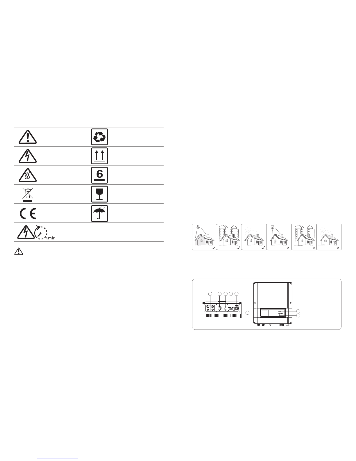
Caution!
Failure to observe a warning indicated in
this manual may result in injury.
Danger of high voltage and electric shock!
Produ ct shoul d not be dispose d as
household waste.
1 Symbols
The SS/DS series inverter of Jiangsu GoodWe Power Supply Technology Co. Ltd. (hereinafter referred to as GoodWe) strictly conforms
to related safety rules in design and test. Safety regulations relevant to the location shall be followed during installation,
commissioning, operation and maintenance. Improper operation may have a risk of electric shock or damage to equipment and
property.(SS: Single-MPPT,Single-Phase; DS: Dual-MPPT, Single-Phase)
● Installation, maintenance and connection of inverters must be performed by qualified personnel, in compliance with local electrical
standards, regulations and the requirements of local power authorities and/or companies.
● To avoid electric shock, DC input and AC output of the inverter must be terminated at least 5 minutes before performing any
installation or maintenance.
O
● The temperature of some parts of the inverter may exceed 60 C during operation. To avoid being burnt, do not touch the inverter
during operation. Let it cool before touching it.
● Ensure children are kept away from inverter.
● Do not open the front cover of the inverter. Apart from performing work at the wiring terminal (as instructed in this manual),
touching or changing components without authorization may cause injury to people, damage to inverters and annulment of the
warranty.
● Static electricity may damage electronic components. Appropriate method must be adopted to prevent such damage to the
inverter; otherwise the inverter may be damaged and the warranty annulled.
01
2 Safety
3 Installation
3.1 Mounting Instruction
●
● For the convenience of checking the LCD display and possible maintenance activities, please install the inverter at eye level.
●Inverters should NOT be installed near inflammable and explosive items. Any strong electro-magnetic equipment should be kept
away from installation site.
● Product label and warning symbol shall be clear to read after installation.
● Please install inverter in the place where is not exposed to direct sunlight, rain and snow.
In order to achieve optimal performance, the ambient temperature should be lower than 45 °C.
Check the scope of delivery for completeness and any visible damage.
02
1 2
3
4
5
7
6
8
1. PV input terminals
2. DC Switch (Optional)
3. USB port
4. RS485 port or
WiFi antenna port
5. AC output terminal
6. LCD display
7. Indicator lights
8. Button
Danger of hot surface!
Components of the product can be recycled.
CE Mark
This side up; the package must always be
transported, handled and stored in such a way
that the arrows always point upwards.
No more than six (6) identical packages may
be stacked on each other.
Keep dr y; the pac kage/produ ct must be
protected from excessive humidity and must be
stored under cover.
Signals danger due to electrical shock and indicates the time (5 minutes) to allow after the
inverter has been turned off and disconnected to ensure safety in any installation operation.
●
inverter may be damaged and the warranty annulled.
● When exposed to sunlight, the PV array generates dangerous high DC voltage. Please operate according to our instructions, or it
will result in danger to life.
● PV modules should have an IEC61730 class A rating.
● If the equipment is used in a manner not specified by the manufacturer, the protection provided by the equipment may be
impaired.
● Completely isolate the equipment should :switch off the DC switch, disconnect the DC terminal, and disconnect the AC terminal
or AC breaker.
● Prohibit inserting or pulling the AC and DC terminals when the inverter is electrified.
Ensure the output voltage of the proposed PV array is lower than the maximum rated input voltage of the inverter; otherwise the
3.2 Inverter Overview and Package
3.2.1 Inverter Overview
The pa ckage/pro duct shou ld be ha ndled
carefully and never be tipped over or slung.
Page 4
320 mm
310 mm
160 mm
130 mm
Figure 3.3.2-2 Figure 3.3.2-3
03 04
260 mm
260 mm
Figure 3.3.2-1
140 mm
115 mm
130 mm
130 mm
160 mm
155 mm
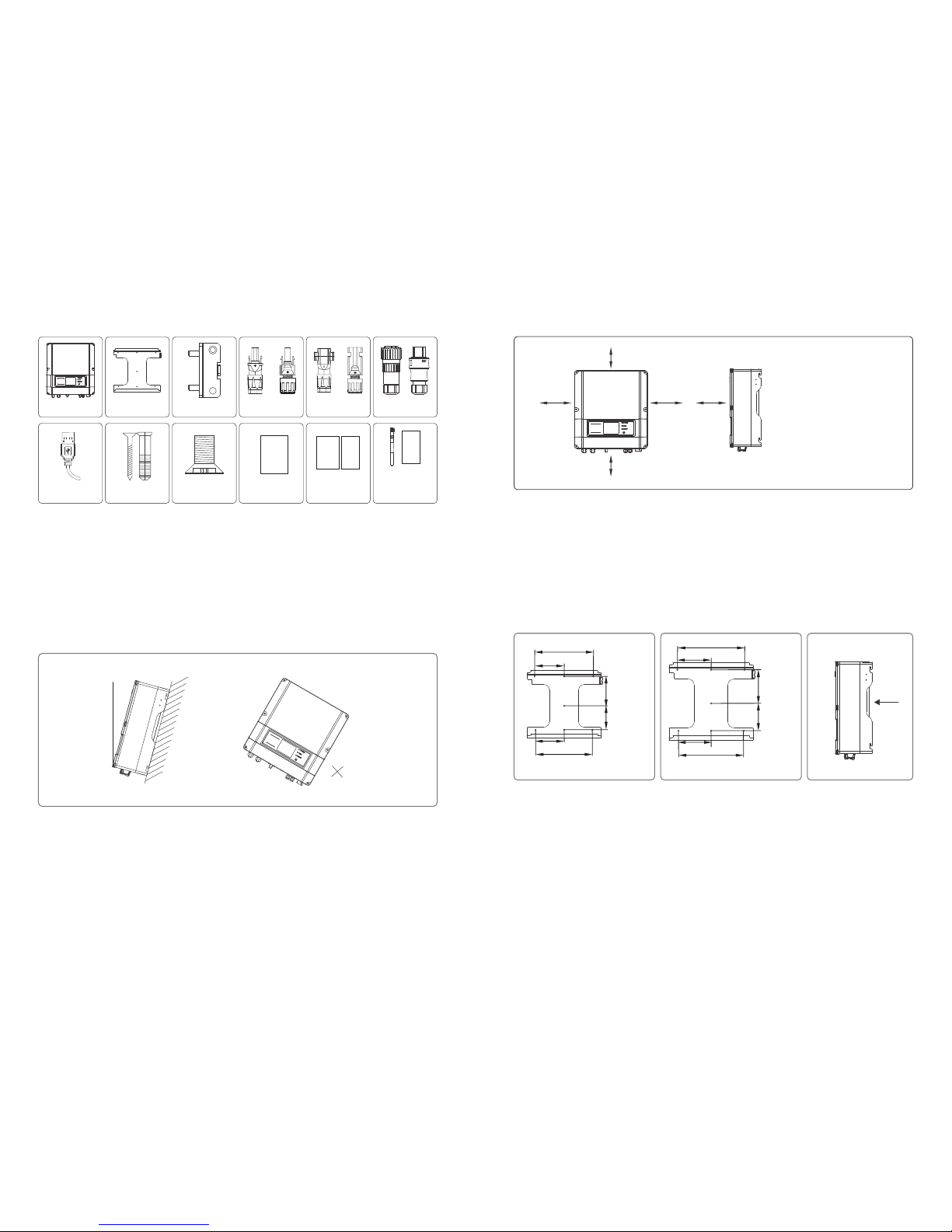
3.2.2 Package
Wall-mounted
Bracket×1
Lock Plate×1
Positive DC Plug×2*
Negative DC
Plug×2*
AC Plug×1
USB Data Cable×1
Expansion Bolts×7
Flat Head Screw×5
User Manual×1
Warranty card×1
Quick Installation
Guide×1
Antenna×1
WiFi Connection
Guide×1
(WiFi model only)
or
Inverter×1
*For GW1500-SS、GW2000-SS the number is 1.
or or
To allow dissipation of heat, and for convenience of dismantling, clearances around the inverter must be at least:
Groove
3.3.1 Selecting the installation location
The following must be considered when selecting the best location for an inverter:
●The mo unt and i nstal latio n metho d must be a pprop riate f or the in verte r's wei ght and d imens ions.
●The lo catio n must be w ell ven tilat ed and sh elter ed from d irect s unlig ht.
●The inver ter mu st be i nstal led ve rtica l or wi th a ba ckward tilt l ess th an 15° . No sid eways tilt i s allo wed. The c onnec tion
are a must po int dow nwards . Ref er to Figu re 3.3. 1-1.
Upwa rd --- --- ----3 00mm
Dow nward- -- --- -- 500m m
Fron t---- ---- ---- -3 00mm
Bot h sides ---- --- --200 mm
Figure 3.3.1-1
200 mm 300 mm
3.3 Inverter Installation
MAX
15°
3.3.2 Mounting Procedure
(1) Use the wall-mounted bracket as a template and drill 7 holes in the wall, 10 mm in diameter and 80 mm deep. The inverter size of
1500W, 2000W, 3000W models can be referred to Figure 3.3.2-1, and the size of other models is as Figure3.3.2-2.
(2) Fix the wall mounting bracket on the wall using the expansion bolts in the accessories bag.
(3) Hold the inverter by the groove on the heat sink as Figure 3.3.2-3.
(4) Place the inverter on the wall-mounted bracket as illustrated in Figure3.3.2-4, 3.3.2-5, 3.3.2-6.
(5) Insert the lock plate pegs into the two holes in the heat-sink, then fix the inverter with a padlock and screw M3x8 as Figure
3.3.2-7, 3.3.2-8.
300 mm
500 mm
200 mm
Figure 3.3.1-2
User
manual
Warranty
Card
Instruction of
Fast Installation
WiFi connection
configuration
Page 5
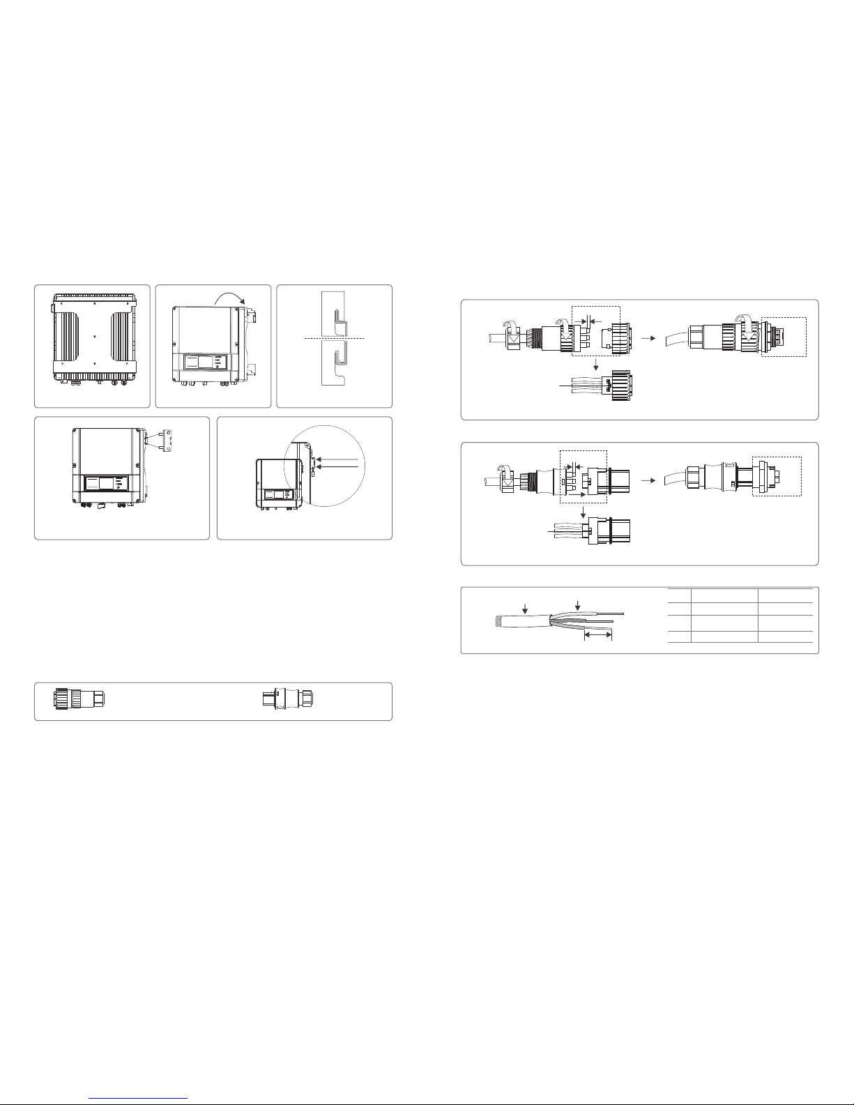
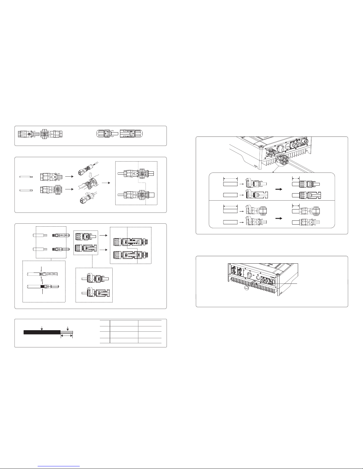
There are two AC connector brands for inverter, VACONN and WIELAND. As is Figure 3.4.1-1
Grade Description
A O.D.
B
C Bare Wire Length
Figure 3.4.1-4
A
B
C
3.4.2 DC Side Connection
10m m
fasten screw cap clockwise
Fastening three screws
to ensure each screw head
is not exceeding the surface
Figure 3.4.1-1
10m m
Inv erter
fasten screw cap clockwise
Cable specification of AC side is showed as Figure 3.4.1-4.
(1)
damage the unit.
(2)The open circuit voltage of the PV strings cannot exceed the maximum input voltage of the inverter.
(3)Only DC connectors provided by us are permitted to use.
(4)The positive and negative pole is forbid to connect PE wire (Ground wire), otherwise, it will damage the unit.
(5)Don't connect positive or negative pole of PV string to PE wire. Otherwise, it will cause damage to inverter.
Before connecting the PV strings, please ensure the plug connectors have the correct polarity. Incorrect polarity could permanently
Installation instruction of WIELAND series is referred to Figure 3.4.1-3.
VACONN Series WIELAND Series
Installation instruction of VACONN series is referred to Figure 3.4.1-2.
Figure 3.4.1-2
Figure 3.4.1-3
05 06
A
B
C
Inv erter
3.4 Electrical Connection
3.4.1 Connection to grid (AC side Connection)
(1) Check the grid voltage and frequency if it can comply with the required voltage and frequency of inverter connection.
(2) It is suggested that the breaker or fuse will be added in the AC side, its current should be over 1.25 times of rated current.
(3) Measure the impedance of neutral wire and ground wire to make sure it’s less than 10 ohm.
(4) Disconnect the breaker or fuse between the inverter and the utility.
(5) Connect the inverter to the grid as follows:
Figure 3.3.2-7 Figure 3.3.2-8
Scr ew M3x8
Loc k
Figure 3.3.2-4 Figure 3.3.2-5 Figure 3.3.2-6
fasten screw cap clockwise
Fastening three screws
to ensure each screw head
is not exceeding the surface
Conductor Material
Sectional Area
Value
10~12mm
2
2.5~4mm
10mm around
Page 6
Grade Description
A O.D.
B
C Bare Wire Length
Conductor Material
Sectional Area
Value
4~5mm
2
2.5~4mm
7mm around
SUNCLIX Series
MC4 Series
Figure 3.4.2-1
0807
3.4.3 USB Communication
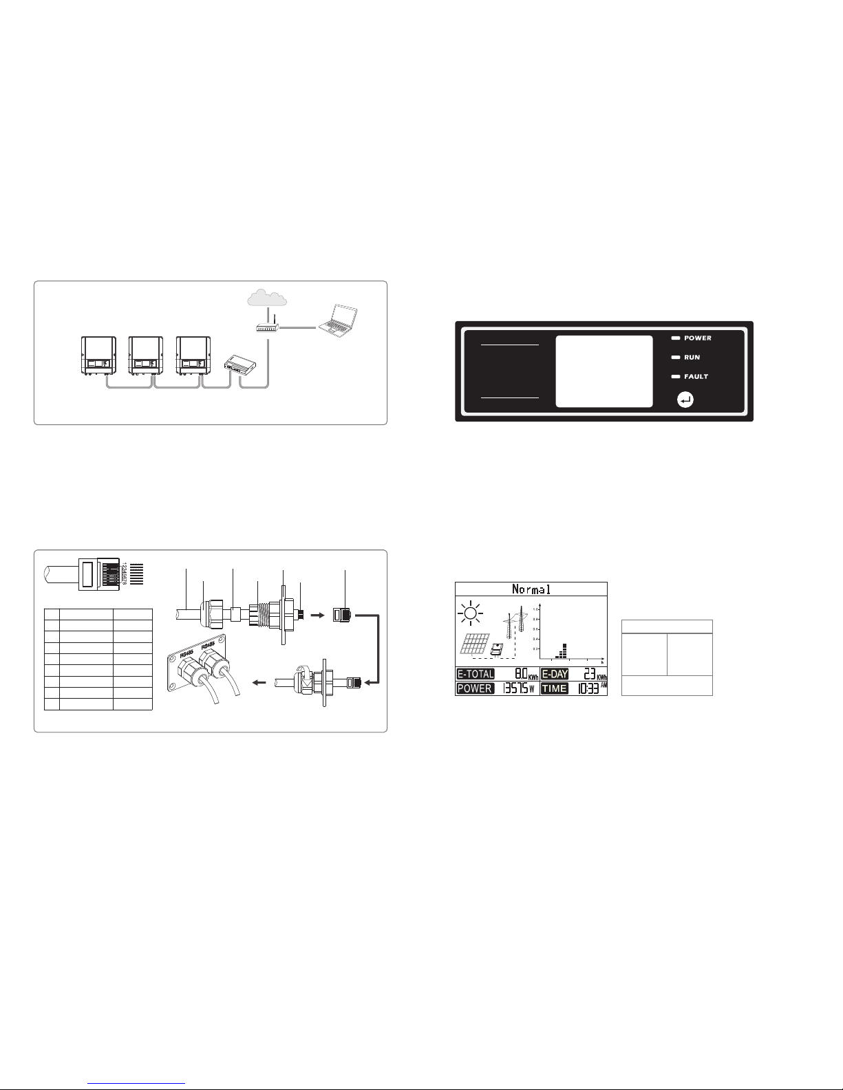
USB cable should be connected as Figure 3.4.3-1
2.Insert the USB data cable
Figure 3.4.3-1
1.Open the USB cover
3.4.4 RS485 Communication
This function is only applied to inverters with RS485.
The RS485 interface is used to connect EzLogger, and the maximum total length of all connecting cables should not exceed 800m.
RS485 connection is referred to 3.4.4-1.
If you need USB monitoring solution, please download EzExplorer software at www.goodwe.com.cn.
For the better protection of internal inverter from water and dust, both pairs of DC connectors provided in the accessory bag should
connect to inverter. If there is only one string, the unused pair should connect to the inverter and also the exposed wire should be
compressed, whose length is at least 15 mm outside the inverter. Refer to the Figure 3.4.2-5.
Figure 3.4.2-5
cable without
copper core compressed
30mm
30mm
15mm
15mm
Positive connector
Negative connector
Figure 3.4.2-3
There are two types of DC connectors, SUNCLIX and MC4 series. Refer to Figure 3.4.2-1.
Installation instruction of SUNCLIX is referred to Figure 3.4.2-2.
Installation instruction of MC4 is referred to Figure 3.4.2-3.
Negative connector
Positive connector
Figure 3.4.2-2
DC Cable specification is showed as Figure 3.4.2-4.
Figure 3.4.2-4
A
B
C
Special tools are used to stitching
Inv erter
Inv erter
cable without
copper core compressed
Page 7
09 10
4.2 User interface and use of the display
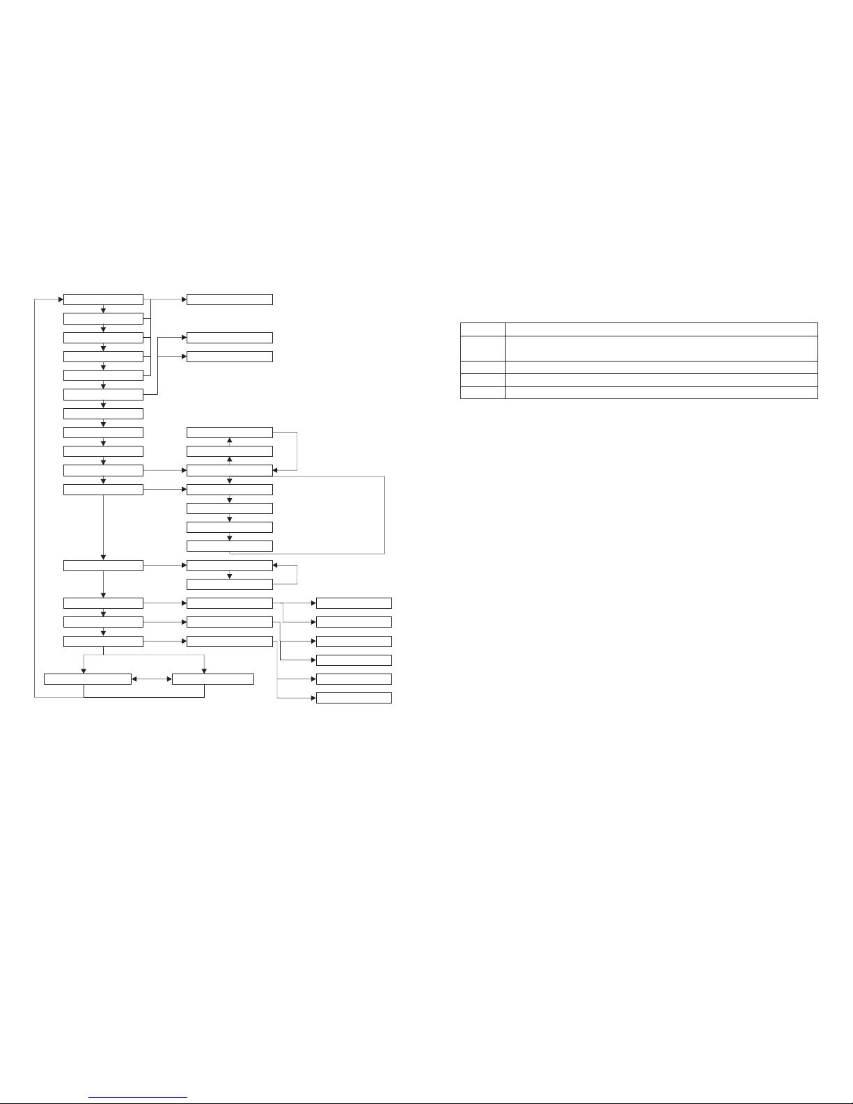
(1) A schematic of the display screen is shown as below:
(2) Display area
Area①---Working status information
● This area displays the status information. “Waiting” indicates the inverter is standby for power generation; “Checking **S”
(checking time is based on safety, and varies from country to country) indicates the inverter is self-checking, counting down and
preparing for power generation. “Normal” indicates the inverter is generating power. If any condition of the system is abnormal,
the screen will display an error message. Refer to Table 4.3.
●Through key operation, the screen can display different information such as operation parameters and power generation status in
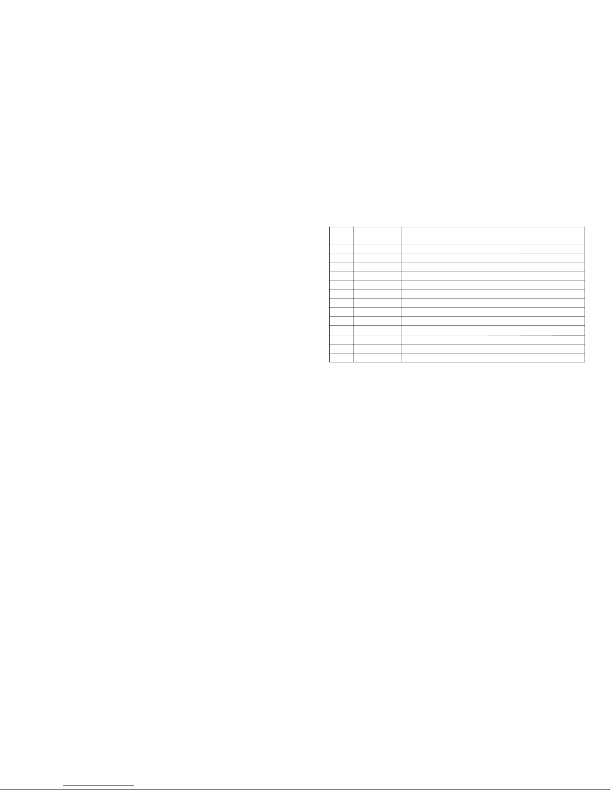
this area. There are two levels of menus, and the flow chart of first level menu is shown below:
Area①
Area② Area③
Area④
Display area is divided as follows:
18126
Indicator lights in Yellow/Green/Red correspondently refer to POWER/RUN/FAULT.
Yellow: Light on indicates the inverter is electrified. For WiFi models, Light flashes on 0.5sec off 0.5sec indicates the WiFi module
doesn’t connect to the WiFi router; Light flashed on 2.5sec off 2.5sec indicates the WiFi module connect to the WiFi router
but cannot receive data from Web Server; Always on indicates communication between Web Server is ok.
Green: Light on indicates the inverter is feeding power. Light off indicates the inverter is not generating power at the moment.
Red: Light on indicates abnormal conditions, while light off indicates normal condition.
4 System Operation
4.1 Indicator Lights
RS485 Communication
Board
Crystal Head
Tighten the screw
in clockwise direction
PIN
Color of the wire
Function
TX_RS485A
TX_RS485B
RX_RS485A
GND
GND
RX_RS485B
Reserved
Reserved
Orange and white
Orange
Green and white
Blue
Blue and white
Green
Brown and white
Brown
1
2
3
4
5
6
7
8
Screw cap
Single hole
seal ring
The insulator
Cables
Figure 3.4.4-2
RS485 waterproof assembly
(2) Connect the inverter to EzLogger with RS485 cable, and EzLogger to switch or router with CAT5E STP cable.
(1)Connection procedure:
●Remove the waterproof kit of RS485 cover with screwdriver.
●Remove the screw cap of the cable gland.
●Remove the one-hole sealing ring.
●Put the RS485 cable through the components in this order: screw cap, one-hole sealing ring, insulation body and sheet metal parts.
●Compress 8 cores of cable into the corresponding interface of crystal head. Refer to Figure 3.4.4-2.
●Connect the compressed crystal head to the communication interface of inverter.
●Fasten the RS485 waterproof kit to inverter.
●Fasten the screw cap of the cable gland.
3.4.5 WiFi Communication
The WiFi communication function is only applied to WiFi models, the detailed configuration instruction can be referred to WiFi
Configuration in the accessory box.
After configuration, please browse http://www.goodwe-power.com to create PV station.
INV ERTER INV ERTER INV ERTER
RS4 85
EzL ogger
RS4 85RS4 85
PCRou ter
Int ernet
Figure 3.4.4-1
Reset
Reload
POWER
LINK
SPEED
RS485
USB
RCR
EzLogger
Cables
Set Safety Country :
If display shows 'Configure Safety', then long press (2S) the key to enter the second level menu. Short press to browse the safety
country available. Choose suitable safety country according to the location of installation. The inverter will store the chosen language
after 20 seconds of no operation.
Page 8
First Level Meum
Status Display
Vpv=325.5V/319.4V
Ipv=7.4A/7.6A
Vac=229.5V
Iac=15.0A
Frequency=50.00Hz
Error Code History
Model Name
Ver. V1.00
Set Language
Set Time
Set Protocol
Zigbee ID Reset
WiFi Reset
WiFi Reload
Lock
No Error
ECode01 110822 01:01
Language:English
Sprache: Deutsch
2000-00-00 00 :00
2000-00-00 00 :00
……
2000-00-00 00 :00
.VS. Monitor Device
.VS. WebServer
ID Resetting...
WiFi Reset ing...
WiFi Reloading...
Jezyk: Angielski
t
ID Reset Failed
ID Reset Successful
WiFi Reset Failed
WiFi Reset OK
WiFi Reload Failed
WiFi Reload OK
Shadow Optimized OFF
Shadow Optimized ON
Short press
Long
press 2s
Waiting 25s
●Menu display can be controlled by pressing the key, and holding the key for a while will enter into the submenu.
Area ②:
●The electrical connection status on DC side and the AC side are represented by dashed lines and full lines. Flashing dashed line on
DC side indicates PV panel is feeding power to the inverter. Nothing shows on AC side means grid is not available.
Full line on AC side means grid is available, but the inverter is not generating power at the moment. Flashing dashed line on AC side
indicates the inverter is feeding power to the grid network.
Area ③:
●Histogram is used to represent the hourly average power generation from 4 a.m. to 8 p.m. for the day. The average power at full
column represents the nominal power of system.
Short press
Short press
Short press
Short press
Short press
Short press
Short press
Short press
Short press
Short press
Short press
Short press
Short press
Short press
or
Short press Short press
Long
press 2s
Long
press 2s
Long
press 2s
Long
press 2s
Long
press 2s
Long
press 2s
Long
press 2s
Sencond Level Meum
Short press
Long press 2s
Short press
Waiting 25s
Waiting 25s
Long
press 2s
Short press to set the third number
Short press to set the fourth number
Short press to set the last number
Short press
Area ④:
● This area shows total power generation, daily power generation, and the power generated at present and time information,
described as follow:
Par t
E-TO TAL
E-D AY
POW ER
TIM E
Description
Power generated for the day
Present power generation of the system
Current system time
Gross power generated from the first use of the inverter. The initial unit is “kWh”; when power generation
exceeds 9999.9kWh, the unit changes to “MWh”.
(3) Use of the display
There are 2 modes of button operation: Short press and long press.
(4) Use of the display and LCD display
The display allows accessing the configuration of the basic parameters. All the language, time and country settings can be
configured by buttons. The menu, shown in the LCD display area has two levels of menu. Short and long key presses will take you
between menus and through each menu. Items in the first level menu that have no second level are locked. For these items, when
the key is pressed for two seconds, the LCD will display the word “Lock” followed by data relating to the first level menu item. The
locked menu can only be unlocked under system mode switching, fault occurrence or key operation.
In all levels of menu, if no action is taken for 20 seconds, the backlight of the LCD display will switch off, the display will
automatically revert to the first item of the first level menu, and any modifications made to the data will be stored into internal
memory.
(5) Menu Introduction
●When the PV panel is feeding power to the inverter, the screen shows the first-level menu.
●The initial display is the first item of the first level menu, and the interface displays the current status of the system. It shows
“Waiting” in the initial state; it shows “Normal” during power generation mode; if there is something wrong with the system, an
error message is shown. Please refer to Table 4.3.
View PV voltage, PV current, grid voltage, current and frequency:
●Short press the key to enter the Vpv menu which displays the PV voltage in “V”.
●Short press the key to enter the Ipv menu which displays the PV current in “A”.
●Short press the key to enter the Vac menu which displays the grid voltage in “V”.
●Short press the key once more to enter the Iac menu which displays the grid current in “A”.
●Short press the key once more to enter the Frequency menu which displays the grid frequency in “Hz”.
●View Error code
Short press the key once more to enter the Error Code History menu.
Long press (2S) the key to enter the second level menu of error detection. The last three inverter error records will be shown by
short pressing the key in this second level menu. The records include error codes (ECodeXX) and error times (110316 15:30). Error
codes and their related faults can be found in Table 4.3.
●View model name and software version:
From the Error Code History item in the first level menu, short press the key once to see Model Name.
Short press the key once more to enter the software version menu which shows the current software version used.
Settings:
●Set language:
Short press the button to enter the Set Language menu. Long press (2S) the key to enter the second level menu. Short press to
browse the languages available. The inverter will store the chosen language after 20 seconds of no operation.
Page 9
11 12
4.3 Error code
An error message will be displayed on the LCD if a fault occurs.
Error message
SPI Failure
EEPROM R/W Failure
Fac Failure
Relay-Check Failure
DC Injection High
Isolation Failure
Vac Failure
PV Over Voltage
Over Temperature
DC Bus High
Ground I Failure
Utility Loss
AC HCT Failure
GFCI Failure
Description
Internal communication failure
Eeprom device failure
Grid frequency out of permissible range
Relay self-checking failure
Overhigh DC current injection
Ground insulation impedance is too low
Grid voltage out of permissible range
Overvoltage at DC input
Over temperature on the case
Overhigh BUS voltage
Overhigh ground residual current
Utility is unavailable
Output current sensor failure
Detection circuit of ground residual current failure
Error Code
01
02
03
07
13
14
15
17
19
21
22
23
31
32
4.4 WiFi Reset & WiFi Reload
The two functions are only available for WiFi model inverters.
WiFi reload function is used to change the WiFi configuration to default value. Please configure the WiFi again as 3.4.5 after using
the function.
Press the key until the LCD displays “WiFi Reset”, then long press (2S) until the LCD displays “WiFi Resetting…”. Stop pressing and
wait for the screen showing “WiFi Reset Successful” or “WiFi Reset Failed”.
Press the key until the LCD displays “WiFi Reload”, then long press (2S) until the LCD displays “WiFi Reloading…”. Stop pressing
and wait for the screen showing “WiFi Reload Successful” or “WiFi Reload Failed”.
●Set time:
From the first level Set Language menu, short press the key to enter the Set Time menu.
Long press (2S) the key to enter the second level menu. The initial display is “2000-00-00 00:00”, in which the first four numbers
represent the year (e.g. 2000~2099); the fifth and sixth numbers represent the month (e.g. 01~12); the seventh and the eighth
numbers represent the date (e.g. 01~31). The remaining numbers represent the time.
Short press to increase the number in current location, and long press to move the cursor to next position. The inverter will store
the time after 20 seconds without any key operation, and the LCD will automatically return to the main menu and the backlight
will switch off.
●Set protocol:
The function is only used for service personnel, set wrong protocol could lead to communication failure.
From the first level Set Time menu, short press the key once to enters set protocol display menu. Press the key for 2S to enter
submenu. The circulatory submenu including two protocols can be found. The protocol can be chosen by short pressing the key. The
inverter will store the chosen protocol without any action within 25S and LCD display will automatically return to main menu when
the backlight is off.
●MPPT function for Shadow:
The default setting for shadow optimizer is disabled.
Please enable shadow optimizer when there is shadow on PV panel. The function could help the system generate more power
under shadow condition.
Please do not enable the function when there's no shadow on panel. Otherwise it could lead to generate less power.
Press the key until enter Shadow Optimize menu. When it shows “Shadow Optimized Off”, it means the MPPT function for shadow
is switched off. Press the key 2S to enable the function. If it shows “Shadow Optimized On” it means the shadow optimizer is on.
Press the key 2S to disable the function.
●70% Rated power limit
The function could only be available for inverter in German. It could only be used by network operator. Otherwise it will cause the
PV plant generated reduced.
Press the key until enter 70% rated power menu. If it shows “70% Rated Enable” it means the function to limit the inverter
working under 70% rated output is switched off. Pressing key 2S will switch this function on. If it shows “Recover Rated Power” it
means inverter is working under 70% of rated output power. Press key 2S will recover inverter to 100% of its rated output power.
(6) Operation of Display when commissioning.
When the input voltage reaches the inverter turn-on voltage, the LCD starts to work, the yellow light is on and the LCD displays
“Waiting”. More information will be displayed within a few seconds. If the inverter is connected to the grid, “Checking 30” will be
displayed and a countdown will commence from 30 seconds. When it shows “00S” you will hear the relay triggered 4 times. The LCD
will then display “Normal”. The instant power output will be shown at the left bottom of the LCD.
Page 10
13 14
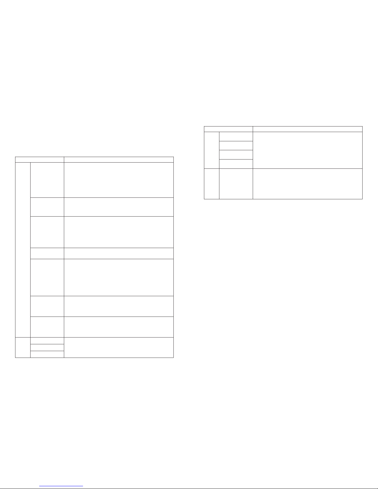
5 Troubleshooting
In mos t situatio ns, the inverter re quires ver y little m aintenance. Ho wever, if the in verter is not working properly, plea se try the
follow ing troubles hooting solu tions:
●When a problem o ccurs, the red (fault) LE D indicato r on the fr ont panel w ill light u p and the LC D screen wi ll display the type
of fault . The followin g table lists er ror messages a nd the solutio ns for associa ted faults.
Dis play
Troub lesho oting
Sys tem
fai lure
Iso latio n Failur e
1.Disc onnect DC sw itch, take off D C connector, Chec k the impeda nce between PV (+)
& PV (-) to ea rth.
2.If im pedance is l ess than 100 kΩ, please chec k the insula tion of PV str ing wiring t o
the eart h.
3.If imp edance is larg er than 100 kΩ, please c ontact local s ervice offic e.
4.Take off AC con nector, m easure the impedanc e be tween neutral and PE. If it is
larger t han 10 kΩ, please c heck AC wiring.
Gro und I Fail ure
1.Disconnect DC switch, check the insulation of PV string wiring to earth.
2.Reconnect the DC switch again.
3.If the problem still exits, please call the local service office.
Vac Fai lure
1.Disc onnect the DC switch, ta king off AC con nector, measurin g the volta ge between
line and neu tral in connect or, make sure i f it con forms to the g rid-connec ted
specif ication of inv erter.
2.If it do es not, please che ck grid wiring .
3.If it does, pl ease conn ect AC conn ector, reconnec t DC swi tch, invert er will connect
grid aut omatically. If the pr oblem still ex its, please call th e local servic e office.
Fac Fai lure
1.The PV Inv erter will aut omatically r estart if the Fac re turns to norma l.
2.If the p roblem still e xits, please call t he local servi ce office.
Invert er
failur e
1.Disconnect the DC switch, take off DC connector, check PV string voltage, make sure if
it exceeds the input voltage in inverter specification.
2.If it does, please reconfigurate PV panel string.
3.If the problem still exits, please call the local service office.
1.Please check if installation position conforms to the specification.
2.Try to lower the surrounding temperature.
3.Move the inverter to vents or alter the installation position.
4.If the problem still exits, please call the local service office.
1.Disconnect the DC connector.
2.Reconnect the DC connector.
3.If the problem still exits, please call the local service office.
PV Ov er Voltag e
Ove r Tempe ratur e
Relay- Check Failure
DC Injec tion High
EEPROM R /W Failure
Uti lity Lo ss
1.Disc onnect t he DC switch, taking o ff AC co nnector, meas ure the voltage between
line and n eutral n conne ctor, make s ure if it co nforms t o the grid-con nected
specif ication of inv erter.
2.If it doe s not, please check i f the distribut ion swi tch is connecte d and the gri d is
normal .
3.If it does, reconn ect AC con nector and DC connecto r; If th e pr oblem still exits,
please c all the local se rvice office.
1.Disconnect the DC switch, take off DC connector, measure the voltage of PV string.
2.Plug in DC connector, and reconnect DC switch.
3.If the voltage is less than 125V, please check the PV string configuration.
4.If the voltage is higher than 125V and still no display, please contact local service
office.
Note: When su nlight is insufficie nt, the PV In verter may continuous ly start u p and shut down automa tically du e to insuff icient
power generate d by the PV panels, w hich wo uld not lead to inver ter dam age. If the prob lem stil l exits, please call th e local
servic e office.
SCI Fa ilure
SPI Fa ilure
DC Bu s High
GFC I Failur e
No di splay
1.Disconnect the DC connector.
2.Reconnect the DC connector.
3.If the problem still exits, please call the local service office.
Invert er
failur e
Dis play Troub lesho oting
Page 11
15 16
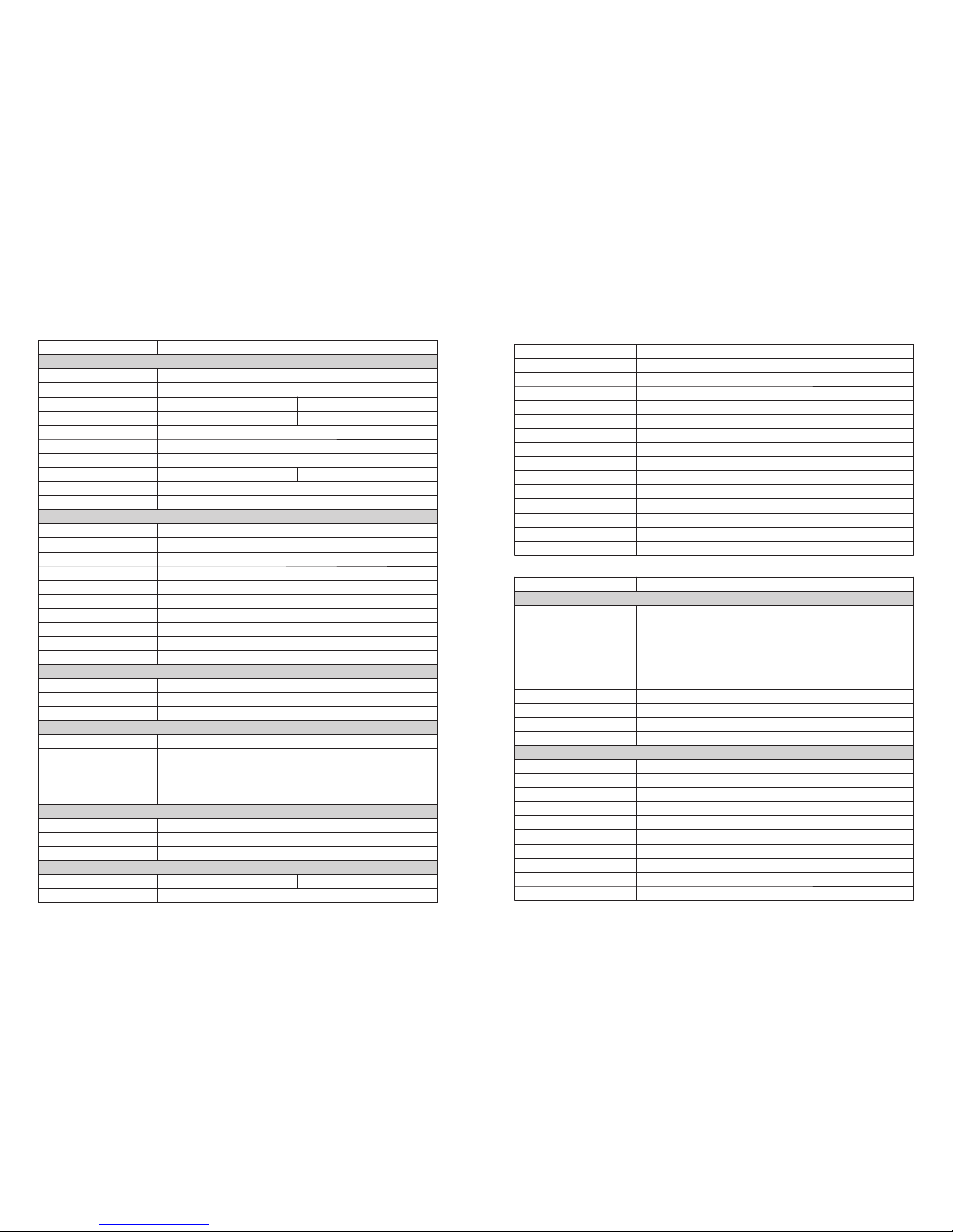
6 Technical Parameters
Model
>99.5%
Integrated
Integrated
Integrated(optional)
Integrated
Integrated
VDE-AR-N 4105, AS4777.2&.3, RD1699, G83/2, IEC62109-2, VDE0126-1-1+A1, EN50438
According to IEC62109-1&-2, AS3100
EN 61000-6-1, EN 61000-6-2, EN 61000-6-3, EN 61000-6-4, EN 61000-3-2, EN 61000-3-3
Category Ⅱ
SUNCLIX / MC4 (optional)
50/60Hz; 230Vac
45~55Hz/55~65Hz; 180~270Vac
<1%
0.9 leading~0.9 lagging
Single Phase
Category Ⅲ
GW1500-SS
1800
450
12
21
1
1500
1650
8
18.5
97. 0%
>96 %
12
GW2000-SS
2300
500
125~450
125
15
21
1
1
2000
2000
10
18.5
97. 0%
>96 %
12
GW3000-SS
3200
500
18
23
2
3000
3000
15
26.5
97. 0%
>96 .5%
13
GW3600-SS
4200
580
20
30
2
3600
4000
16
37
97. 8%
>97 .4%
18
GW4000-SS
4600
580
125~550
125
20
30
2
1
4000
4400
22
37
97. 8%
>97 .4%
18
GW4600-SS
5400
580
20
30
2
4600
5100
25
43
97. 8%
>97 .4%
18
355 *380* 134mm 390 *417* 142mm
Model
*
*
DC input Data
Max. DC power(W)
Max. DC voltage (V)
MPPT voltage range (V)
Starting voltage (V)
Max. DC current (A)
DC overcurrent protection(A)
No. of DC connectors
No. of MPPTs
DC overvoltage category
DC connector
AC Output Data
Norminal AC power(W)
Max. AC power(W)
Max. AC current(A)
AC overcurrent protection(A)
Norminal AC output
AC output range
THDi
Power factor
Grid connection
AC overvoltage category
Efficiency
Max. efficiency
Euro efficiency
MPPT adaptation efficiency
Protection
Residual current monitoring unit
Anti-islanding protection
DC switch
AC over current protection
Insulation monitoring
Certifications&Standards
Grid regulation
Safety
EMC
General Data
Dimensions (WxHxD)
Weight (kg)
Mounting
Ambient temperature range
Relative humidity
Moisture location category
Max. operating altitude
Protection degree
Environment category
External environment pollution degree
Topology
Night power consumption(W)
Cooling
Noise emision(dB)
Display
Communication
Standard warranty(years)
DC input Data
Max. DC power(W)
Max. DC voltage (V)
MPPT voltage range (V)
Starting voltage (V)
Max. DC current (A)
DC overcurrent protection(A)
No. of DC connectors
No. of MPPTs
DC overvoltage category
DC connector
AC Output Data
Norminal AC power(W)
Max. AC power(W)
Max. AC current(A)
AC overcurrent protection(A)
Norminal AC output
AC output range
THDi
Power factor
Grid connection
AC overvoltage category
Wall Mounting
-25~60°C (>45°C derating)
0~95%
4K4H
2000m
IP65
Outdoor & indoor
Grade1、2、3
Transformerless
<1
Natural Convection
<25
4.0'' LCD
USB2.0;RS485 or WiFi
5/10/15/20/25(optional)
GW4 600-D S
540 0
15/ 15
21
460 0
510 0
25
43
GW4200-DS
4600
580
125~550
125
15/15
21
2
2(can parallel)
Category Ⅱ
SUNCLIX / MC4 (optional)
4200
4400
21
43
50/60Hz; 230Vac
45~55Hz/55~65Hz; 180~270Vac
<1.5%
0.9 Leading~0.9 Lagging
Single phase
Category Ⅲ
GW3600-DS
3800
10/10
21
3600
3600
18
35
Page 12
17
IEC62109-1&-2, AS3100
EN 61000-6-1,EN 61000-6-2,EN 61000-6-3,EN 61000-6-4, EN 61000-3-11, EN 61000-3-12
7 Certificates
59
VDE0126-1-1
产
品
金
伏
太
光
阳
能
认
阳
证
太
VDE-AR-N 4105 62109-2 EN50438 NRS097-2-1 RD1699 MEA&PE A
GW3 600-D S GW4 200-D S GW4 600-D S
Model
Integrated
Integrated
Integrated(optional)
Integrated
Integrated
97. 6%
>97 %
97. 8%
>97 .4%
>99 .5%
97. 8%
>97 .4%
Note
Overvo ltage catego ry definitio n
Catego ry I : applie s to equipme nt connected to a circuit w here measur es have been t aken to reduce transient o vervoltage t o a
low leve l.
Catego ry II : app lies to equ ipment not permanentl y connecte d to the in stallation . Examp les are ap pliances, port able tools and
other pl ug-connect ed equipment ;
Catego ry III: applie s to fixed equip ment downstr eam of and inclu ding, the main dis tribution bo ard. Examples ar e switchgear
and othe r equipment in a n industrial i nstallatio n;
Catego ry IV: applies t o equipment pe rmanently co nnected at the o rigin of an inst allation (up stream of the mai n distributi on
board) . Exampl e are electric ity meters, prima ry overcurre nt protectio n equipment an d other equipm ent connecte d
direct ly to outdoor op en lines.
Enviro nment catego ry definitio n
Outdoo r : the ambi ent air temper ature is -20~5 0°C, Relative hu midity range i s 4 % to 100 %, applied t o PD3
Indoor u ncondition ed: the ambient ai r temperatur e is -20~50°C, Re lative humid ity range is 5 % to 95% ,applied to PD 3
Indoor c onditioned : the ambi ent air temper ature is 0~40° C, Relative humi dity range is 5 % to 8 5%,applied t o PD2
Pollutio n degree defi nition
Pollutio n degree 1: No pol lution or only d ry, non-con ductive poll ution occurs. The pollu tion has no infl uence.
Pollutio n degree 2: Norm ally only non- conductive p ollution occ urs. Occasional ly, however, a tempo rary conduct ivity caused b y
conden sation must be e xpected.
Pollutio n degree 3: Cond uctive pollu tion occurs, or, dry, non-condu ctive pollut ion occurs whi ch becomes con ductive due to
conden sation which i s expected.
Pollutio n degree 4: Persi stent conduc tive polluti on occurs, for exam ple, the pollution c ause by conduc tive dust, rain a nd snow.
18
*
lis ted in th e table.
It is r ecomm ended t hat the t otal pe ak powe r of PV str ings sh ould no t excee d 130% of m aximu m DC power o f inver ter
Efficiency
Max. efficiency
Euro efficiency
MPPT adaptation efficiency
Protection
Residual current monitoring unit
Anti-islanding protection
DC switch
AC over current protection
Insulation monitoring
Certifications&Standards
Grid regulation
Safety
EMC
General Data
Dimensions (WxHxD)
Weight (kg)
Mounting
Ambient temperature range
Relative humidity
Moisture location category
Max. operating altitude
Protection degree
Environment category
External environment pollution degree
Topology
Night power consumption(W)
Cooling
Noise emision(dB)
Display
Communication
Standard warranty(years)
390*417*165mm
20
Wall Mounting
-25~60°C (>45°C derating)
0~95%
4K4H
2000m
IP65
Outdoor & indoor
Grade1、2、3
Transformerless
<1
Natural Convection
<25
4.0'' LCD
USB2.0;RS485 or WiFi
5/10/15/20/25(optional)
Moistu re
parame ters
Lev el
Temperatu re Range
Humidi ty Range
3K3
0~+ 40℃
5%~ 85%
4K2
-33 ~+4 0℃
15% ~10 0%
4K4 H
-20 ~ +55 °C
4%~ 100 %
Moistu re location ca tegory defin ition
VDE-AR-N 4105,
AS4777.2&.3,
RD1699, IEC62109-2,
VDE0126-1-1+A1, EN50438
VDE-AR-N 4105,
AS4777.2&.3, RD1699,
G59/2, IEC62109-2,
VDE0126-1-1+A1, EN50438
VDE-AR-N 4105,
AS4777.2&.3, MEA, PEA
RD1699, G59/2, IEC62109-2,
VDE0126-1-1+A1, EN50438,
 Loading...