

Page 1
PV Master APP SEMS Portal APP SEMS Portal website
www.semsportal.com
LinkedIn Company's
offical website
JIANGSU GOODWE POWER SUPPLY TECHNOLOGY CO.,LTD
No. 90 Zijin Rd., New District, Suzhou, 215011, China
www.goodwe.com
[email protected]
BT SERIES USER MANUAL
AC-COUPLED BATTERY STORAGE RETORFIT
340-00330-00
Page 2
TABLE OF CONTENTS
INTRODUCTION
1.1 OPERATION MODES INTRODUCTION
1.2 SAFETY & WARNINGS
1.3 PRODUCT OVERVIEW
INSTALLATION INSTRUCTIONS
2.1 UNACCEPTABLE INSTALLATIONS
2.2 PACKING LIST
2.3 MOUNTING
2.3.1 SELECT MOUNTING LOCATION
2.3.2 MOUNTING
2.4 ELECTRICAL WIRING CONNECTION
2.4.1 BATTERY CONNECTION
2.4.2 ON-GRID & BACK-UP CONNECTION
2.4.3 SMART METER & CT CONNECTION
2.5 DRED & EARTH FAULT ALARM
2.5.1 DRED CONNECTION
2.5.2 EARTH FAULT ALARM
MANUAL OPERATION
01
02
04
05
05
06
06
07
08
08
09
12
13
13
14
3.1 WI-FI CONFIGURATION & WI-FI RELOAD
3.2 GEI AUTO-TEST INSTRUCTION
3.3 CEI AUTO-TEST FUNCTION
OTHERS
4.1 ERROR MESSAGE AND TROUBLESHOOTING
4.2 DISCLAIMER
4.3 TECHNICAL PARAMETERS AND CERTIFICATES
4.4 WARINING QUICK CHECK LIST
17
18
18
19
25
26
28
Page 3
01 INTRODUCTION
GoodWe BT series bi-directional inverter is designed for both indoor and outdoor use, which could be
used with or without existing grid-tied inverter systems to store energy with batteries.
Energy produced from grid-tied inverters shall be used to optimize self-consumption, then charge
battery, exceed power from grid-tied system could export to grid. Loads will be supported in priority by
grid-tied system, then battery power, exceed consumption power will be drained from grid.
Note:
The introduction describes a general behavior of ET system.
The operation mode can be adjusted on GoodWe PV Master
APP depends on the system layout. Below are the general
operation modes for BT system:
01
1.2 SAFETY & WARNING
The BT series inverter of Jiangsu GoodWe Power Supply Technology Co., Ltd. (hereinafter called as
GoodWe) strictly comply with related safety rules for product design and testing. Please read and follow
all the instructions and cautions on the inverter or user manual during installation, operation or mainte-
nance, as any improper operation might cause personal or property damage.
•
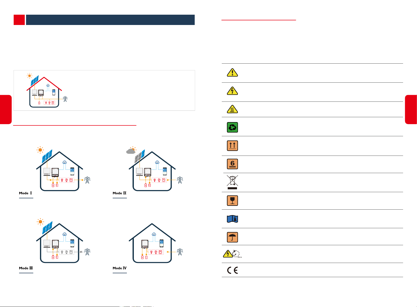
SYMBOLS EXPLANTION
Caution!
Failing to observe a warning indicated in this manual may result in injury.
Danger of high voltage and electric shock!
Danger of hot surface!
02
1.1 OPERATION MODES INTRODUCTION
BT system normally has the following operation modes based on your configuration and layout
conditions.
Energy from grid-tied inverters optimize loads, then
charge battery, exceed power export to grid.
When grid power fails, battery will discharge to support
Back-Up Loads.
When energy from grid-tied inverters is weak, battery
discharge to support loads in priority, together with grid.
Battery could be charged by grid, and charge time/power
could be set flexibly on PV Master APP.
Components of the product can be recycled.
This side up! The package must always be transported, handled and stored in such a
way that the arrows always point upwards.
No more than six (6) identical packages being stacked on each other.
Product should not be disposed as household waste.
The package/product should be handled carefully and never be tipped over or slung.
Refer to the operating instructions.
Keep dry! The package/product must be protected from excessive humidity and must
be stored under cover.
Inverter will be touchable or operable after minimum 5 minutes of being turned off or
totally disconnected, in case of any electrical shock or injury.
CE Mark
Page 4

•
SAFETY WARNING
Any installation and operation on inverter must be performed by qualified electricians, in compliance
with standards, wiring rules or requirements of local grid authorities or companies (like AS 4777 and
AS/NZS 3000 in Australia).
Prohibit to insert or pull the AC and DC terminals when the inverter is running.
Before any wiring connection or electrical operation on inverter, all DC and AC power must be
disconnected from inverter for at least 5 minutes to make sure inverter is totally isolated to avoid
electric shock.
The temperature of inverter surface might exceed 60℃ during working, so please make sure it
is cooled down before touching it, and make sure the inverter is untouchable for children
1.3 PRODUCT OVERVIEW
FAULT
BLINK1 = OVERLOAD OF BACK-UP
BLINK4 = CT WIRING FAULT
OFF = NO FAULT
OUTPUT / REDUCE LOAD
WiFi
BLINK 1 = WiFi SYSTEM RESETTING
BLINK 2 = WiFi NOT CONNECT TO ROUTER
BLINK 4 = WiFi SERVER PROBLEM
OFF = WiFi NOT ACTIVE
ON = FAULT HAS OCCURRED
OFF = BMS AND METER COMMUNICATION FAIL
ON = WiFi CONNECTED / ACTIVE
METER COMMUNICATION FAIL
ENERGY
COM
BLINK 1 = METER COMMUNICATION OK,
BLINK 2 = BMS COMMUNICATION OK,
BLINK 2 = SUPPLYING ENERGY TO GRID / SELLING
OFF = GRID NOT CONNECTED OR SYSTEM NOT OPERATING
ON = BMS AND METER COMMUNICATION OK
BMS COMMUNICATION FAILI
GRID
BLINK = GRID IS ACTIVE BUT NOT CONNECTED
OFF = GRID IS NOT ACTIVE
ON = CONSUMING ENERGY FROM GRID / BUYING
BLINK 1 = SUPPLYING ENERGY TO GRID / ZEROING
BACK-UP
BATTERY
OFF = SYSTEM IS NOT OPERATING
ON = BACK-UP IS READY / POWER AVAILABLE
OFF = BACK-UP IS OFF / ON POWER AVAILABLE
ON = BATTERY IS CHARGING
BLINK 1 = BATTERY IS DISCHARGING
BLINK 2 = BATTERY IS LOW / SOC IS LOW
OFF = BATTERY IS DISCONNECTED / NOT ACTIVE
ON = GRID IS ACTIVE AND CONNECTED
INDICATOR
SYSTEM
ON = SYSTEM IS READY
BLINK = SYSTEM IS STARTING UP
SYSTEM BACK-UP BATTERY GRID ENERGY COM WiFi FAULT
STATUS
EXPLANATION
HYBIRD LED INDICATORS
03
Do not open inverter cover or change any components without GoodWe’s authorization,
otherwise the warranty commitment for the inverter will be invalid.
Usage and operation of the inverter must follow instructions in this user manual, otherwise the
protection design might be useless and warranty for the inverter will be invalid.
Appropriate methods must be adopted to protect inverter from static damage. Any damage
caused by static is not warranted by GoodWe.
Battery negative(BAT-) on inveter side is not grounded as default design.
Connecting BAT- to EARTH are strictly forbidden.
The inverter, with built-in RCMU, will exclude possibility of DC residual current to 6mA, thus in
the system an external RCD (type A) can be used(≥30mA).
In Australia, the inverter internal switching does not maintain neutral integrity, which must be
addressed by external connection arrangements like in the s Off-Grid System Connection
Diagram in page 16.
In Australia, output of Back-Up side in switchbox should be labeled ‘Main switch UPS supply’,
the output of normal load side in switch box should be labeled ‘main switch inverter supply’.
Battery Terminals
Wi-Fi Box
To Battery
BMS Communication Cable
SmartMeter Communication Cable
DRED
To Smart Meter
Back-Up Port
04
Wi-Fi Reset LED Lable
OFF
On-Grid Port
Page 5
INSTALLATION INSTRUCTIONS02
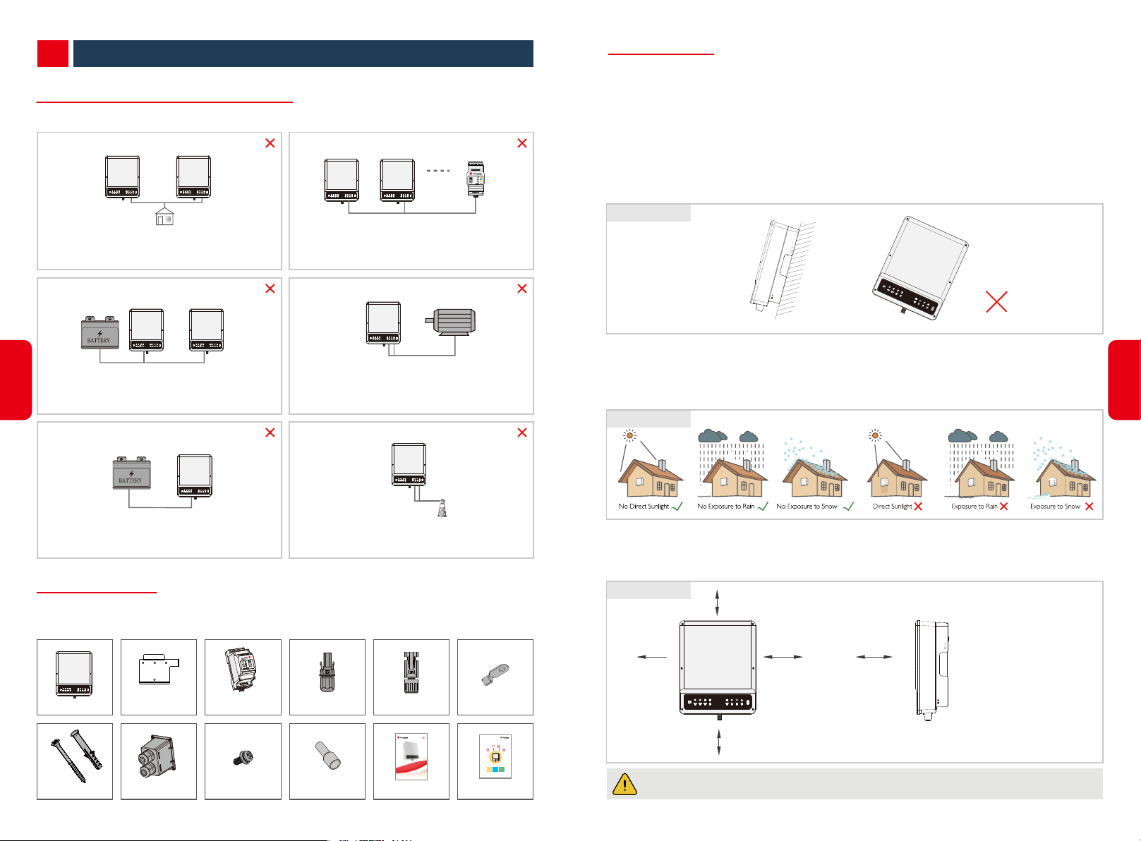
2.1 UNACCEPTABLE INSTALLATIONS
Please avoid the following installations,which will damage the system or the Inverter.
Back-Up Back-Up
BACK-UP CANNOT CONNECT IN PARALLEL.
Load
ONE METER CANNOT CONNECT TO MULTIPE
INVERTERS. AND DIFFERENT CT CANNOT CONNECT
TO A SAME LINE CABLE.
Generator
SmartMeter
2.3 MOUNTING
2.3.1 SELECT MOUNTING LOCATION
For inverter’s protection and convenient maintenance, mounting location for inverter should be
selected carefully based on the following rules:
Any part of this system shouldn’t block the switch and breaker to disconnected inverter from DC and
AC power.
Rule 1. Inverter should be installed on a solid surface, where is suitable for inverter’s dimensions and
weight.
Rule 2. Inverter installation should stand vertically or lie on a slop by max 15° (Figure 2.3.1-1)
Figure 2.3.1-1
On-Grid
05
ONE BATTERY BANK CANNOT BE CONNECT TO MULTIPLE
INVERTERS.
BatteryBattery
Back-Up
ON-GRID OR BACK-UP SIDE CANNOT CONNECT
TO ANY AC GENERATOR.
Incompatible battery
Battery
INVERTER BATTERY INPUT CANNOT CONNECT TO
INCOMPATIBLE BATTERIES.
Back-Up
BACK-UP SIDE CANNOT CONNECT TO GRID.
On-Grid
2.2 PACKING LIST
On receiving the hybrid inverter, please check to make sure all the components as below are not missing
or broken.
Wall-mounted
Bracket×1
Expansion bolts×4 AC Cover×1 Pan head screw×6
Smart Meter *1
with 3 CT
Positive BAT Plug×1
Pin Terminal × 12 User Manual × 1
Negative BAT Plug×1Inverter×1
BT SERIES USER MANUAL
AC-COUPLED BATTERY STORAGE RETORFIT
PE terminal × 1
UPS
BT QUICK INSTALLATION INSTRUCTIONS
PART 1
PART 2
PART 3
QUICK
BATTERY
Wi-Fi
INSTALLATION
CONNECTION
CONFIGURATION
Quick Installation
Guide × 1
Rule 3. Ambient temperature should be lower than 45°C
(High ambient temperature will cause power derating of inverter.)
Rule 4. The installation of inverter should be protected under shelter from direct sunlight or bad Rule
weather like snow, rain, lightning etc. (Figure 2.3.1-2)
Figure 2.3.1-2
Rule 5. Inverter should be installed at eye level for convenient maintenance.
Rule 6. Product label on inverter should be clearly visible after installation.
Rule 7. Leave enough space around inverter following the values in Figure 2.3.1-3.
Figure 2.3.1-3
300mm
200mm 200mm 300mm
500mm
Inverter cannot be installed near flammable, explosive or strong electro-magnetic equipment.
Upward
---------- 300mm
Downward
Front
Both sides
------ 500mm
------------- 300mm
-------- 200mm
[1]
06
Page 6
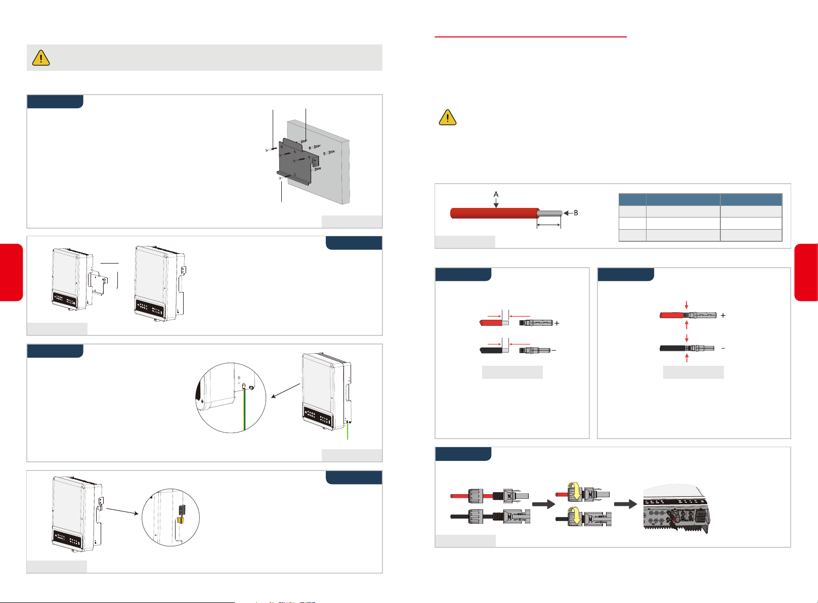
2.3.2 MOUNTING
Remember that this inverter is heavy! Please be careful when lifting out from the package.
The inverter is suitable for mounting on concrete or other non-combustible surface only.
07
Step 1
• Please use the mounting bracket as a template to drill
4 holes on right positions. (10mm in diameter, and
80mm in depth) (Figure 2.3.2-1)
• Use expansion bolts in accessory box and fix the
mounting bracket onto the wall tightly.
Note: Bearing capacity of the wall must be higher than
25kG, otherwise may not be able to keep inverter
from dropping.
Carry the inverter by holding the heating sink
on two sides and Place the inverter on the
mounting bracket. (Figure 2.3.2-2)
Note: Make sure the heat sink on inverter is
Figure 2.3.2-2
Step 3
Wall bracket Expansion pipe
self-tapping
screw
right joint with mounting bracket.
[2]
Figure 2.3.2-1
Step 2
2.4 ELECTRICAL WIRING CONNECTION
2.4.1 BATTERY WIRING CONNECTION
•Please be careful against any electric shock or chemical hazard.
•Make sure there is an external DC breaker (≥40A) connected for battery without build-in DC
breaker.
Make sure battery switch is off and battery nominal voltage meet BT series’ specification before
connecting battery to inverter and make sure inverter is totally isolated from AC power.
Please following requirements and step bellow strictly. Use improper wire may cause bad
contact and high impedance, which is dangerous to the system.
•
Use the right BAT plugs in the accessory box.
•
Use the tin-plated cables with a conductor cross section of 4 to 6 mm² (AWG 10) because the
maximum battery current is 25A. Battery cable requirements are as (
Grade
A
C
Figure 2.4.1-1
B
C
Figure 2.4.1-1
Description
Outside diameter insulation
Conductor core section
Conductor core length
).
Value
5.5-8.0 mm
4-6 mm
7 mm
Battery wiring connection steps as below:
Step 1
Prepare BAT cables and BAT plugs
(Figure 2.4.1-2)
7mm
7mm
Step 2
Connect BAT cables to BAT connectors
(Figure 2.4.1-3)
[4]
2
08
Ground cable shall be connected to
ground plate on grid side (Figure
2.3.2-3)
Figure 2.3.2-4
Figure 2.3.2-3
Step 4
A lock could be used for anti-theft if it is
necessary for individual requirement.
(Figure 2.3.2-4)
Note:
Figure 2.4.1-2
•Please use BAT plugs and connectors in
GoodWe accessory box
•BAT cable should be standard, 4-6mm
BAT cable
Note:
•BAT cable must be tightly crimped into the
connectors
2
•There will be a click sound if connectors are inset
correctly into BAT plugs
Figure 2.4.1-3
Step 3
Screw the cap on and plug onto inverter side (Figure 2.4.1-4)
Note:
•There will be a click
sound if connectors
are inset correctly
into BAT plugs.
Figure 2.4.1-4
Note:For the compatible lithium batteries (Pylon/BYD) connection, please refer to battery connection
part in BT quick installation instructions.
Page 7
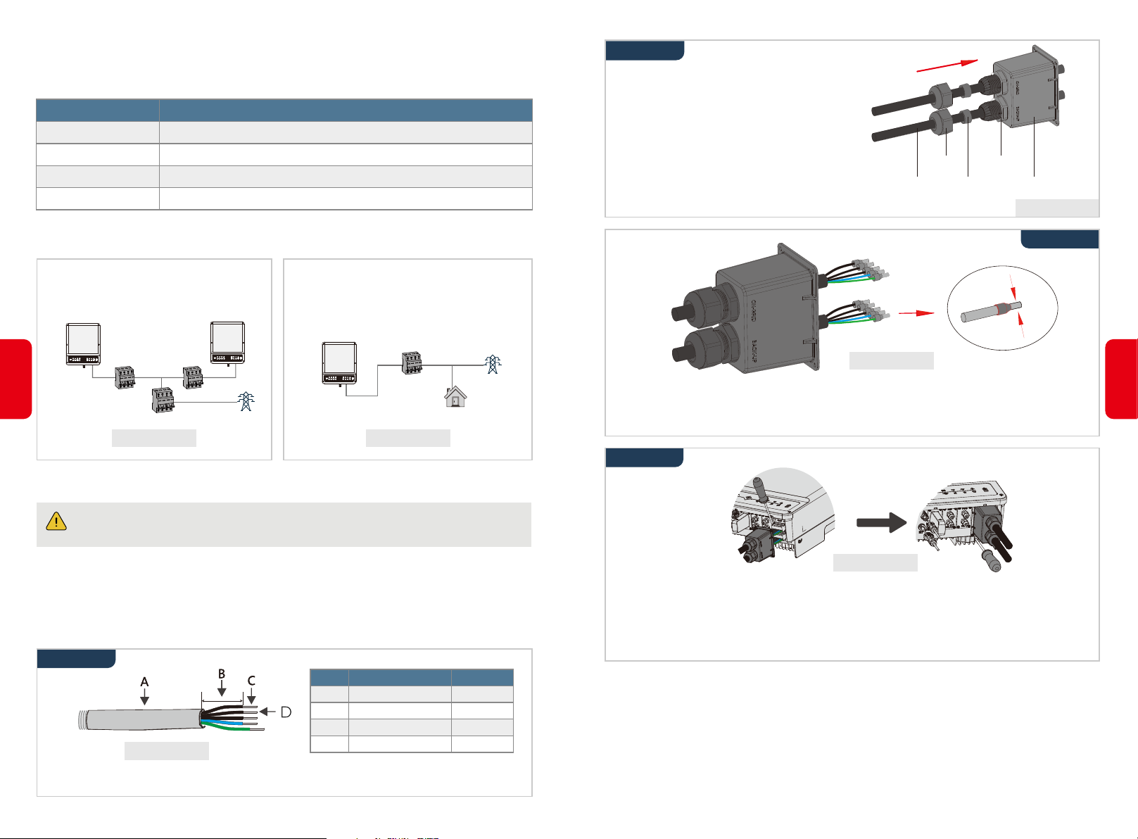
2.4.2 ON-GRID & BACK-UP CONNECTION
An external AC breaker is needed for On-Grid connection to be isolate from grid when necessary.
Below are the requirements of On-Grid AC breaker.
Inverter model
GW5K-BT
GW6K-BT
GW8K-BT
GW10K-BT
Note:The absence of AC breaker on Back-up side will lead to inverter damage if only electrical short
circuit happend on back-up side.
AC breaker specification
25A / 400V (e.g. DZ47-60 C25)
25A / 400V (e.g. DZ47-60 C25)
32A / 400V (e.g. DZ47-60 C32)
32A / 400V (e.g. DZ47-60 C32)
Step 3
Put AC cable through terminal cover follow the
sequence as on the right(Figure 2.4.2-4)
Note:Please use the terminals in GoodWe
components box
Cables
Screw cap
Single hole
seal ring
The insulator
AC sheet cover
Figure 2.4.2-4
Step 3
1. Use separate AC breaker for individual
inverter (Figure 2.4.2-1)
2. On AC side, the individual breaker should
be connected before loads (between
inverter and loads)( Figure 2.4.2-2)
AC breaker
09
AC breaker
AC breaker
Grid
AC breaker
Loads
Figure 2.4.2-1 Figure 2.4.2-2
• Requirement of AC cable connected to On-Grid and Back-Up side(Figure 2.4.2-3)
Make sure inverter is totally isolated from any DC or AC power before connecting AC
[5]
cable.
Note
1. Neutral cable shall be blue, line cable is black or brown (preferred) and protective earth cable
yellow-green.
2. For AC cables, PE cable shall be longer than N&L cables, so that if in any case AC cable slips or taken
out, the protecting earth conductor will be the last to take the strain.
Step 1
Grade
Description
A
Outside diameter
B
Separated wire length
C
Conductor wire length
D
Figure 2.4.2-3
Conductor core section
Grid
Value
13-18 mm
20-25 mm
7-9 mm
4-6 mm
Figure 2.4.2-5
10
Press the 10 connectors on cable conductor core tightly(Figure 2.4.2-5)
Note:Make sure cable jacket is not locked within the connector
Step 4
Screwing torque
2.0-2.5N.m
Figure 2.4.2-6
1. Connect the assembled AC cables into AC terminals with fastening torque about 2.0-2.5N.m.
Note: Connecting Back-up terminals before connect On-grid terminals.
Make sure it is not connected to a wrong side.
2. Lock the cover and screw the cap on (Figure 2.4.2-6)
Special Adjustable Setting
The inverter has filed adjustable setting like tripping point, tripping time, reconnect time, active and
invalid of QU/PU curves etc. by special firmware. Please contact GoodWe after sales for the special
2
firmware and adjust methods.
Prepare the terminals and AC cables according to the right table.
Page 8
Declaration For Back-Up Function
GoodWe BT series bi-directional inverters are able to supply over load output power at its' back-up.
For details please refer to the technical parameters of GoodWe BT series inverter(4.3 se)
And the inverter has self-protection derating at high ambient temperature.
The below statement lays out GoodWe general policies governing the energy storage inverters of the
series ES, EM, SBP, ET, EH,BH and BT.
1. For Hybrid inverters (Series ES, EM, EH and ET), the standard PV installation typically consists of the
connection of the inverter with both panels and batteries. In case of systems not connected to the
batteries, the Back-Up function is strongly not advised to use. GoodWe shall not cover the standard
warranty and be liable for any consequences arising from users not following this instruction.
2. Under normal circumstances, the Back-Up switching time is less than 10 ms (the minimal condition
to be considered as the UPS level). However, some external factors may cause the system to fail on
Back-Up mode. As such, we recommend the users to be aware of conditions and follow the
instructions as below:
1) Do not connect loads if they are dependent on a stable energy supply for a reliable operation
2) Do not connect the loads which may in total exceed the maximum Back-Up capacity
3) Try to avoid those loads which may create very high start-up current surges such as Inverter
Air-conditioner, high-power pump etc.
4) Due to the condition of battery itself, battery current might be limited by some factors including but
not limited to the temperature, weather etc.
11
Accepted loads as below:
• Inductive Load: 1.5P non-frequency conversion air-conditioner can be connect to back-up side. Two
or more non-frequency conversion air-conditioner connect to back-up side may cause UPS mode
unstable.
• Capacitive Load: Total power <= 0.6 x nominal power of model. (Any load with high inrush current
at start-up is not accepted.)
• For complicated application, please contact GoodWe's after service.
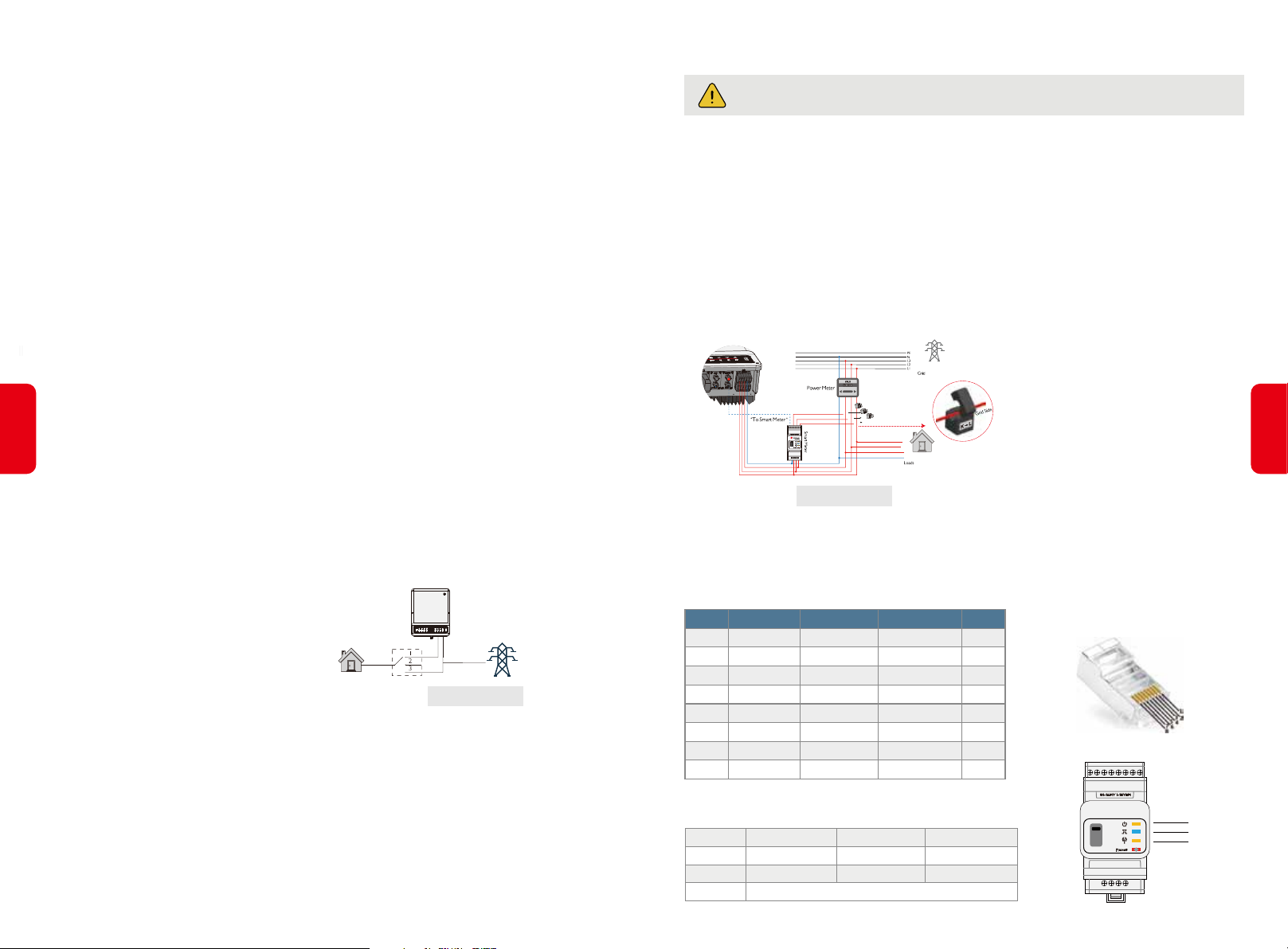
Note:
For a convenient maintenance, Please installed a
“4Pole3Throw”on Back-Up and On-Grid side. Then it
1. Load is supplied from Back-Up side.
2. Load is isolated.
3. Load is supplied from grid side.
is adjustable to support load by Back-Up or by grid or
just leave it there. (Figure 2.4.2-7)
Figure 2.4.2-7
Declaration For Back-Up Overload Protection
Inverer will restart itself as overload protection happens. The preparation time for restarting will be
longer and longer (max one hour) if overload protection repeats. Take following steps to restart inverter
immediately.
• Decrease Back-up load power within max limitation
• On PV Master → Adcanced Setting → Click “Reset Back-Up Overload History”.
2.4.3 SMART METER & CT CONNECTION
Make sure AC cable is totally isolated from AC power before connecting Smart Meter &
[6]
C T.
The Smart Meter with CT in GoodWe product box is compulsory for BT system installation, used to
detect grid voltage and current direction and magnitude, further to instruct the operation condition of
BT inverter via RS485 communication.
Note
1. The Smart Meter with CT is well configured, please do not change any setting on Smart Meter.
2. One Smart Meter can only be used for one BT inverter.
3. Three CTs must be used for one Smart Meter, and must be connected on the same phase with Smart
Meter power cable.
•Smart Meter & CT Connection Diagram(Figure 2.4.2-7)
Note:
1. Please use the Smart Meter with 3 CTs in
GoodWe product box.
CT C
CT B
CT A
CT A connect to L1
CT B connect to L2
CT C connect to L3
Figure 2.4.2-7
•Detailed pin function of each port on BT
Note:For BMS cable, CAN communication is configured by default. If 485 communication is
used,please contact GOODWE to replace with the corresponding communication line.
1
2
3
4
5
6
7
8
Color
Orange&white
Orange
Green&white
Blue
Blue&white
Green
Brown&white
Brown
BMS Function
485_A2
NC
485_B2
CAN_H
CAN_L
NC
NC
NC
Smart Meter Function
NC
NC
485_B1
NC
NC
485_A1
485_B1
485_A1
Position
•Smart Meter LED Indications
POWER
ENERGY
COM
OFF
Not working
/
Blink one time when it transfer data to inverter
ON
Working
Importing
Blinking
Exporting
2. CT cabke is 3m as default, could be
extended to max 5m.
3. Smart Meter communication cable (RJ45)
is attached on the inverter (”To Smart
Meter” cable), could be extended to max
100m, and must use standard RJ45 cable
and plug, as below:
RS485
485_A
485_B
485_A
NC
NC
485_B
NC
NC
/
POWER
ENERGY
COM
12
Page 9
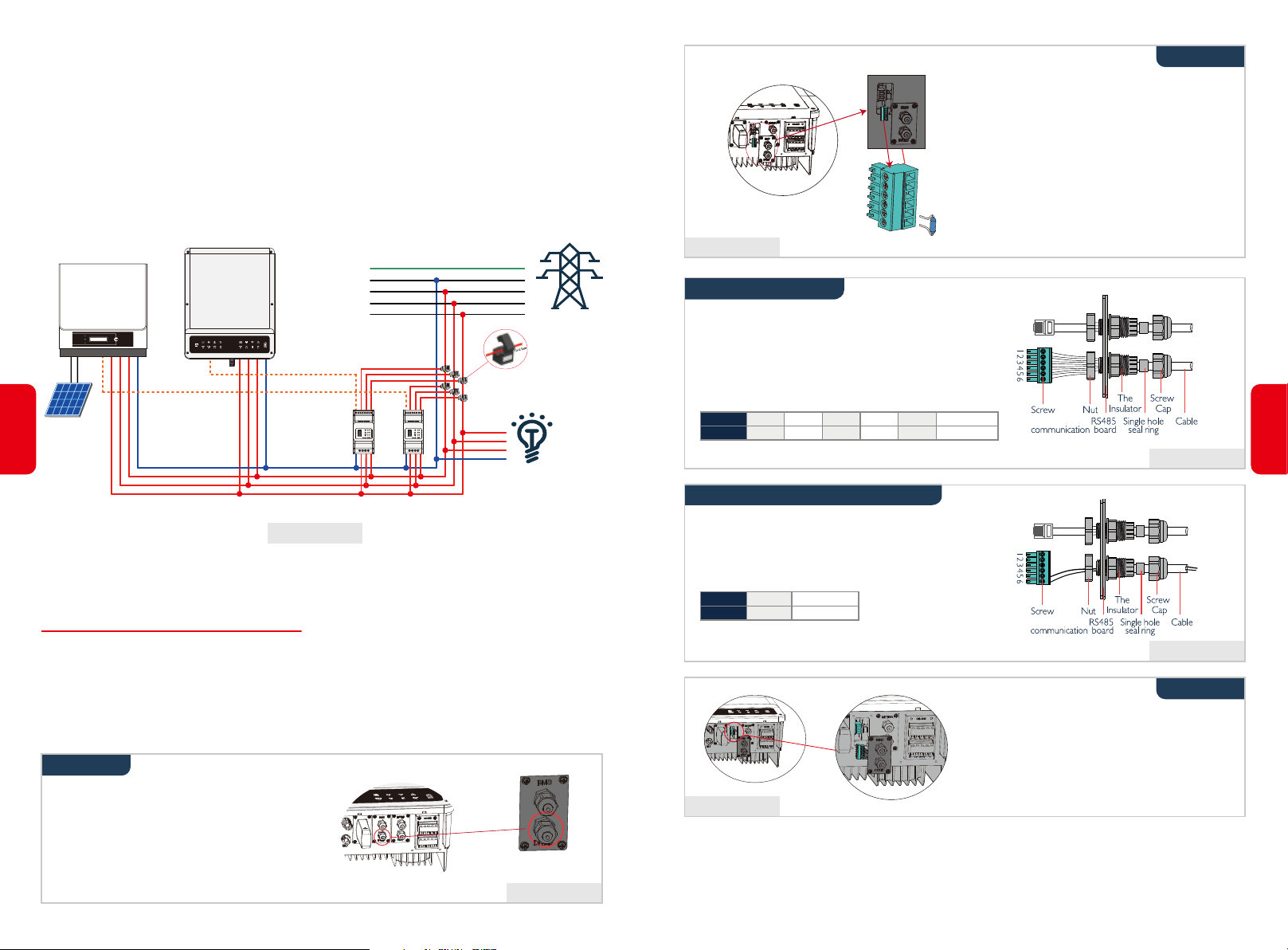
Anti-Reverse Function Connection
If BT system (connected with grid-tied inverters) requires anti-reverse function, it is operable but
please note:
1. This diagram is only for installation where has exporting power limit function requirement.
2. For anti-reverse function, will also need set on PV Master App→Advanced Setting→Power Limit.
3. This diagram only be reasonable if grid-tied inverter has anti-reverse function itself. And the power
limitation value shall be set on grid-tied inverter.
4. When using anti-reverse function, it would buy about 150W from the grid.
•Connection Diagram as below (Figure 2.4.2-8)
GoodWe-BT
13
Grid-Tied Inverter
“To SmartMeter”
PV
“Anti-Reverse connection”
PE
N
L3
L2
L1
CT
CT
Load
[1]
Figure 2.4.2-8
[1] This cable is a theoretical connection supporting anti-reverse function, which could be different for
different grid-tied inverters.
2.5 DRED & EARTH FAULT ALARM
2.5.1 DRED CONNECTION
DRED is used for Australia and New Zealand installation (also used as remote shutdown function in
European countries), in compliance with Australia and New Zealand safety requirements( or European
countries). And DRED device is not provided by GoodWe.
Detailed connection of DRED device is shown below:
Step 1
Grid
Figure 2.5.1-2
Step 3-1 For DRED
1. Put DRED cable through the plate as shown in
Figure 2.5.1-3.
2. Connect DRED cable on the 6-pin terminal.The
function of each connection position
NO
Function1DRM1/52DRM2/63DRM3/74DRM4/85REFGEN6COM / DRMO
Step 3-2 For Remote Shutdown
1. Put the cable through the plate as shown in Figure
2.5.1-4.
2. Wiring from the No. 5 and 6 holes respectively.
NO
Function5REFGEN6COM / DRMO
Step 2
1. Plug out the 6-pin terminal and dismantle
the resistor on it (Figure 2.5.1-2).
2. Plug the resistor out, leave the 6-pin
terminal for next step.
Note: The 6-pin terminal in the inverter has
the same function of DRED device.
Please leave it in the inverter if no
external device connected.
14
Figure 2.5.1-3
Figure 2.5.1-4
Step 4
Connect DRED terminal to the right position onto
the inverter. (Figure 2.5.1-5)
Screw this plate off from inverter. (Figure 2.5.1-1)
Note: DRED device should be connected through
“DRED port” as the figure shows.
Figure 2.5.1-1
Figure 2.5.1-5
2.5.2 EARTH FAULT ALARM CONNECTION
GoodWe BT series inverter complies with IEC 62109-2 13.9. Fault indicator LED on inverter cover will
light up and the system will email the fault information to customer.
Page 10
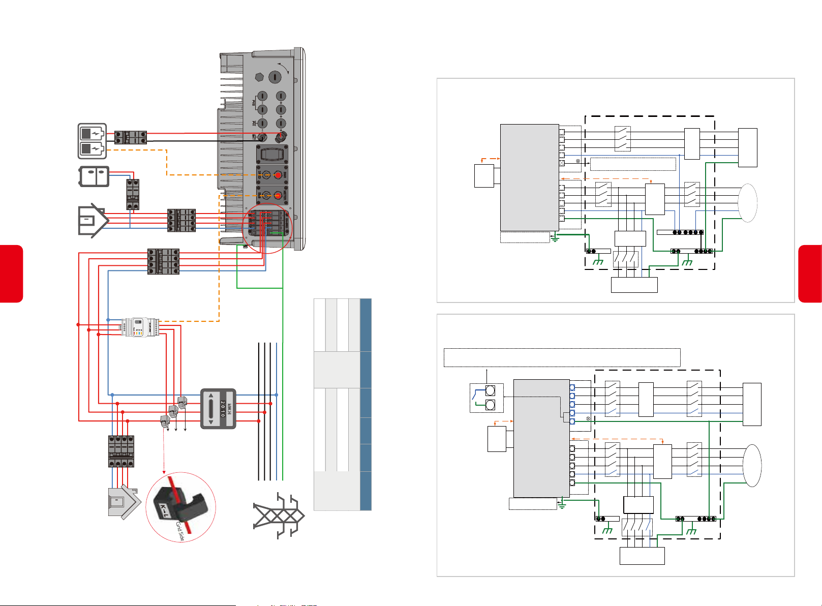
15
OFF
ON
①
DC Breaker
To Battery
Loads
Battery
1-phase
AC Breaker
Loads
②
3-phase
③
AC Breaker
1. For batteries with attached breaker, the external DC breaker could be omitted.
2. Please use CT A for L1, CT B for L2 and CT C for L3. And follow “House(K) →
Grid(L)” direction to do the connection. Otherwise there will be an error reminded
by APP.
AC Breaker
④
“To Smart Meter”
•WIRING SYSTEM FOR BT SERIES HYBRID INVERTER
Note: This diagram indicated wiring structure of BT series AC coupled
inverter, not the electric wiring standard.
Please select Breaker according to the specification below
GW5K-BT
GW6K-BT
GW8K-BT
GW10K-BT
•SYSTEM CONNECTION DIAGRAMS
Note: For Australia safety country, the neutral cable of On-Grid side and Back-Up side must be connected
together, otherwise Back-Up function will not work.
This diagram is an example for application that Neutral connect together with PE in distribution box.
Such as: Australia, NewZealand, South Africa, etc. (Please follow local wiring regulations!)
E-BAR
Distribution box
RCD
L1 L2 L3 N PE
Normal Loads
Smart
Meter
N-BAR
E-BAR
RCD
Link
L1
L2
Back-up
L3
Loads
N
PE
L1
L2
L3
Grid
N
PE
E-N
BMS
Battery
GoodWe BT Series
AC Coupled Inverter
The Grounding screw hole
at the lower right corner
L1
L2
L3
N
Back-up
Meter
L1
L2
L3
N
PE
On-Grid
Don ’t connect this terminal for Neutral
orPE
connect together with PE application .
16
AC Breaker
Loads
⑤
SmartMeter
CT C
CT B
CT A
AC Breaker
Grid
This diagram is an example for application that Neutral separate with PE in distribution box.
Such as: China, Germany, Czech Republic, Italy, etc. (Please follow local wiring regulations!)
40A/600V DC
breaker
32A/400V AC breaker
32A/400V AC breaker
25A/400V AC breaker
25A/400V AC breaker
①
②
③
④
Depends on
PE
L3
L2
L1
N
household
loads
⑤
the Back-Up side neutral and the PE are connected together via the internal relay when inverter
work in Back-up mode, and this internal relay will be open when inverter work in Grid-tied mode.
Distribution box
N
PE
BMS
Battery
GoodWe BT Series
AC Coupled Inverter
The Grounding screw hole
at the lower right corner
L1
L2
L3
N
Back-up
Meter
L1
L2
L3
N
PE
On-Grid
RCD
orPE
Smart
Meter
RCD
E-BAR
L1 L2 L3 N PE
Normal Loads
E-BAR
L1
L2
Back-up
L3
Loads
N
PE
L1
L2
L3
Grid
N
PE
Page 11
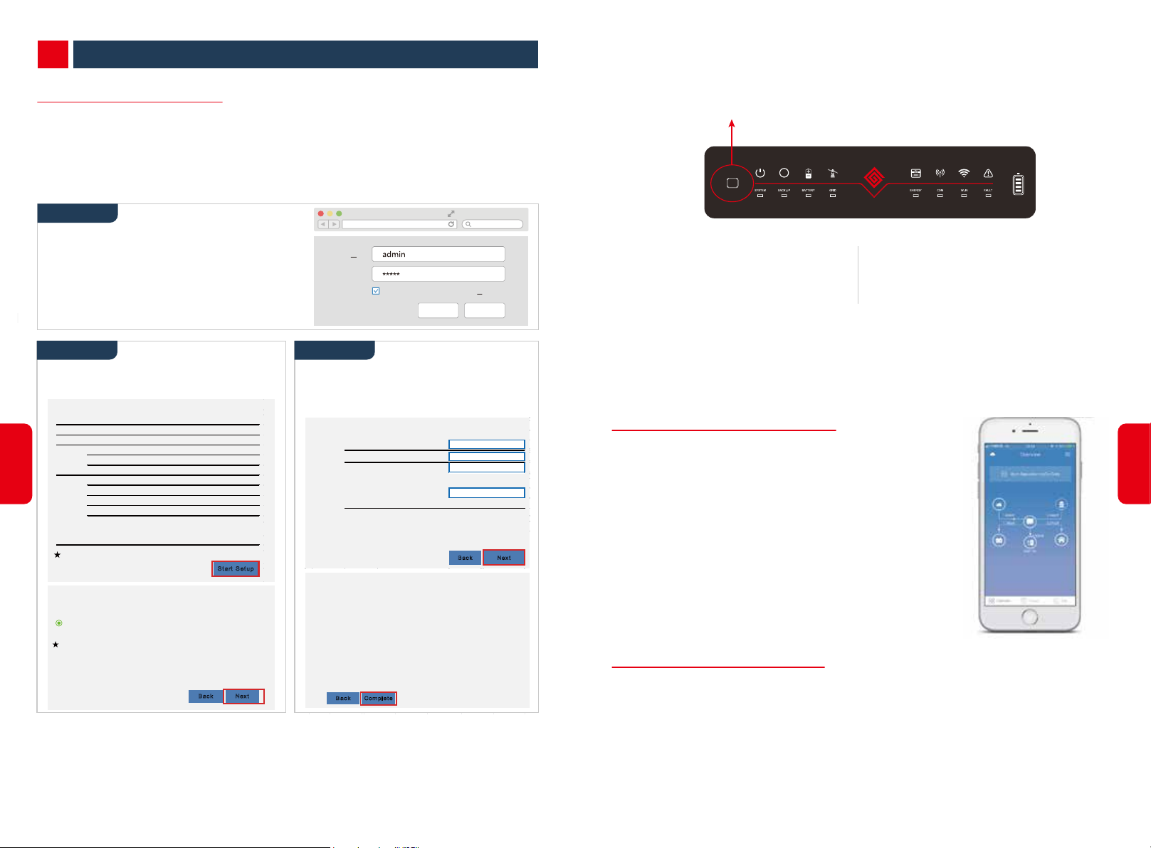
MAMUAL OPERATION03
3.1 WIFI CONFIGURATION
• This part shows configuration on web page.
• Wi-Fi configuration is absolutely necessary for online monitoring and after-sales maintenance.
PREPARATION:
1. Inverter must be powered up with Battery or grid power.
2. Need a router with available internet access to GoodWe portal
https://www.semsportal.com
•
Wi-Fi Reset & Reload
Wi-Fi Reset means restarting Wi-Fi module, Wi-Fi settings will be reprocessed and saved automatically.
Wi-Fi Reload means setting Wi-Fi module back to default factory setting.
Wi-Fi Reset Button
Wi-Fi
RESET
UPS
17
Step 1
1. Connect Solar-WiFi* to your PC or smart
phone(* means the last 8 characters of the
inverter serial No.)
Admin( U):
Password:
2. Open browser and login 10.10.100.253
Admin (U): admin; Password: admin
3. Then click “OK”
Step 2 Step 3
1. Click “Start Setup” to choose your router
2. Then click “Next”
Device information
Firmware verison
MA C address
Wireless AP mode
SS ID
IP address
Wireless STA mode
Router SS ID
Encryption method
Encryption algorithm
Router Pass word
Can not join the ne twork, may be c aus ed by:
router doesn't exist, or signal is too week, or password is incorrect
Hel p:
Wizard will help you to complete setting within one mimute.
Please select you r current wireless network:
SS ID Sec mode Enc type Channel RSS I
WIFI Test WAP 2-PSK A ES 6 54%
Note: When R SSI of the selected WiF i Network is lower than 10%, the
connection may be unstable, pleas e select other available network or
shorten the distance between the devic e and the router.
If your wireless router does not broadc ast SSID, please click "Next" and
add a wireless network manually.
1.6.9. 3.38.2. 1.38
60:C5: A8:60: 33:E 1
E nable
Solar-WiFi
10.10.100. 253
Dis abl e
WiFi_B urn-in
WA P/WAP 2-PSK
WiFi_B urn-in
St art Set up
Bac k Nex t
AE S
1. Fill in the password of the router, then
click “Next”
2. Click “Complete”
Add wireless network manually
Pl eas e e nter the wireles s network pas s word:
Note: cas e sensitive for SS ID and password
Please make sure all parameters of wireless network are matched with router,
including password
Save succ ess!
Click 'Complete', the current configuration will take effect after
restart.
If you still need to c onfigure the other pages of information, please
go to complete your required configuration.
Configuration is completed, you can log on the Management page
to restart device by C lic k on 'OK' button.
Confirm to c omplete?
Bac k Com plet e
10.10.100.253
Remember the password( R)
Network name (SS ID)
Encryption method
Encryption algorithm
Pas sword (8-63 bytes)
OK
WiF i- T es t
WP A /WP A2 -P SK
AE S
hello good we
CANCEL
show psk
Bac k Nex t
Wi-Fi Reset
short press Reset button
Wi-Fi Led will blink for a few seconds
Wi-Fi Reload
long press Reset button (longer than 3s)
Wi-Fi Led will double blink until doing
Wi-Fi configuration again.
Note: Wi-Fi Reset & Reload function is only used when:
1. Wi-Fi lost connection to internet or cannot connect to PV Master APP successfully.
2. Cannot find “Solar-WiFi signal” or have other Wi-Fi configuration problem.
3. Please do not use this button if Wi-Fi monitoring works well.
3.2 PV MASTER APP OPERATION
PV Master is an external monitoring/ configuration application for
GoodWe hybrid inverters, used on smart phones or pad for both
Android and iOS system, main functions as below:
1. Edit system configuration to make the system work as customer
needs.
2. Monitor and check performance of the hybrid system.
3. Wi-Fi configuration.
Please download PV Master OPERATION INSTRUCTIONS from
https://en.goodwe.com/
3.3 CEI AUTO-TEST FUNCTION
PV Auto-Test function of CEI is integrated in PV Master APP for Italy safety country requirement. For
O
M
V
e
p
o
detailed instruction of this function please reger to
P
a
e
n
s
t
a
r
r
t
I
i
o
n
u
n
c
s
r
t
s
t
i
.
18
Note:
1. Please make sure the password, Encryption Method/Algorithm is right the same with the router’s.
2. If everything is right well, the Wi-Fi LED on inverter will change from double blink to quartic blink then to
solid status, which means Wi-Fi is connected to GoodWe server successfully.
3. Wi-Fi configuration could also be done on PV Master, details please check on PV Master APP.
Page 12

OTHERS04
4.1 ERROR MESSAGE AND TROUBLESHOOTINGS
• ERROR MESSAGE
The error message below will be displayed on PV Master APP or reported by Email if the error really
happens.
ERROR MESSAGE EXPLANATION REASON SOLUTIONS
19
Utility Phase Failure
Utility Loss
VAC Failure
FAC Failure
BAT Over Voltage
Over Temperature
Isolation Failure
Ground Failure
The sequence of On-grid wire is wrong
Not available of public grid power
(power lost or on-grid connection fails)
Grid voltage is not within permissible range
Grid Efficiency is not within permissible range
BAT voltage is too high
Temperature inside of the inverter is too high
Ground insulation impedance of Battery is
to low
Ground leakage current is over-high
Inverter detects that phase angle of L2 and L3 are reversed
Inverter does not detect the connection of grid
Inverter detects that AC voltage is beyond the normal
range required by the safety country
Inverter detects that Grid frequency is beyond the
normal range required by the safety country
The battery voltage is higher than the max BAT input
voltage of the inverter.
Inverter working environment leads to a high
temperature condition
Isolation failure could be caused by multi reasons like Battery
are not grounded well,DC cable is broken ,battery are aged
or surrounding humidity is comparatively heavy,etc.
Ground I failure could be caused by multi reasons
like neutral cable on AC side is not connected well
or surrounding humidityis comparative heavy, etc.
Reverse connection order of L2 and L3 cable
1. Check (use multi-meter) if AC side has voltage . Make sure grid power is available.
2. Make sure AC cables are connected tightly and right well.
3. If all is well, please try to turn off AC breaker and turn on again after 5 mins.
1. Make sure safety country of the inverter is set right.
2. Check (use multi-meter) if AC voltage (Between L & N) is within a normal range (Also on AC breaker side)
a. if AC voltage is high, then make sure AC cable complies with that required on user manual and AC cable is not too long
b. if voltage is low, make sure AC cable is connected well and the jacket of AC cable is not compressed into AC terminal
3. Make sure the grid voltage of your area is stable and within normal range.
1. Make sure safety country of the inverter is set right.
2. If safety country is right, then please check on inverter display if AC frequency (Fac) is within a normal range.
3. If FAC failure only appear a few times and resolved soon, it should be caused by occasional
Check battery voltage is lower than Max Battery Input Voltage of the inverter. If voltage of Battery is high, please reduce battery module.
1. Try to decrease surrounding temperature.
2. Make sure the installation complies with the instruction on inverter user manual.
3. Try to close inverter for 15 mins, then start up again.
1. Use multi meter to check if the resistance between earth & inverter frame is about zero. If it's not, Please make the connection
between earth & inverter frame well.
2. If the humidity is very high, there maybe Isolation Failure cocur.
3. Check the resistance between BAT to earth, if the resistance is lower than 33.3k, check the system wiring connection.
4.Try to restart the inverter, check if the fault is still happens, if not, means it is just an occasional situation, or contact GoodWe.
Check (use multi-meter) if there is voltage (normally should be close to 0V) between earth & inverter frame. If the is a voltage, it means
the neutral & ground cable are not connected well on AC side. If it happened only at early morning, dawn or on rainy days with higher
air humidity, and recover soon, it should be normal.
grid frequency unstability.
20
Relay Check Failure
DC Injection High
EEPROM R/W Failure
SPI Failure
DC Bus High
Back-Up Over Load
Self checking of relay fails
/
/
Internal communication fails
BUS voltage is over-high
Back-up side is over loaded
Neutral & ground cable are not connected well on AC
side or just occasional failure
Inverter detects a higher DC component in AC output
Caused by a strong external magnetic field etc.
Caused by a strong external magnetic field etc.
/
Total Back-Up load power is higher than the nominal
backup output power
Check (use multi-meter) if there is high voltage (normally should be lower than 10V) between N & PE cable on AC side. If the voltage
higher than 10V, it means the Neutral & ground cable are not connected well on AC side or restart inverter.
Try to restart inverter,check if it still happens.If not,it is just an occasional situation.Otherwise, contact GoodWe immediately.
Try to restart inverter,check if it still happens.If not,it is just an occasional situation.Otherwise, contact GoodWe immediately.
Try to restart inverter,check if it still happens.If not,it is just an occasional situation.Otherwise, contact GoodWe immediately.
Try to restart inverter,check if it still happens.If not,it is just an occasional situation.Otherwise, contact GoodWe immediately.
Decrease Back-Up loads to make sure the total load power is lower than Back-Up nominal output power (please refer to page 12).
Page 13
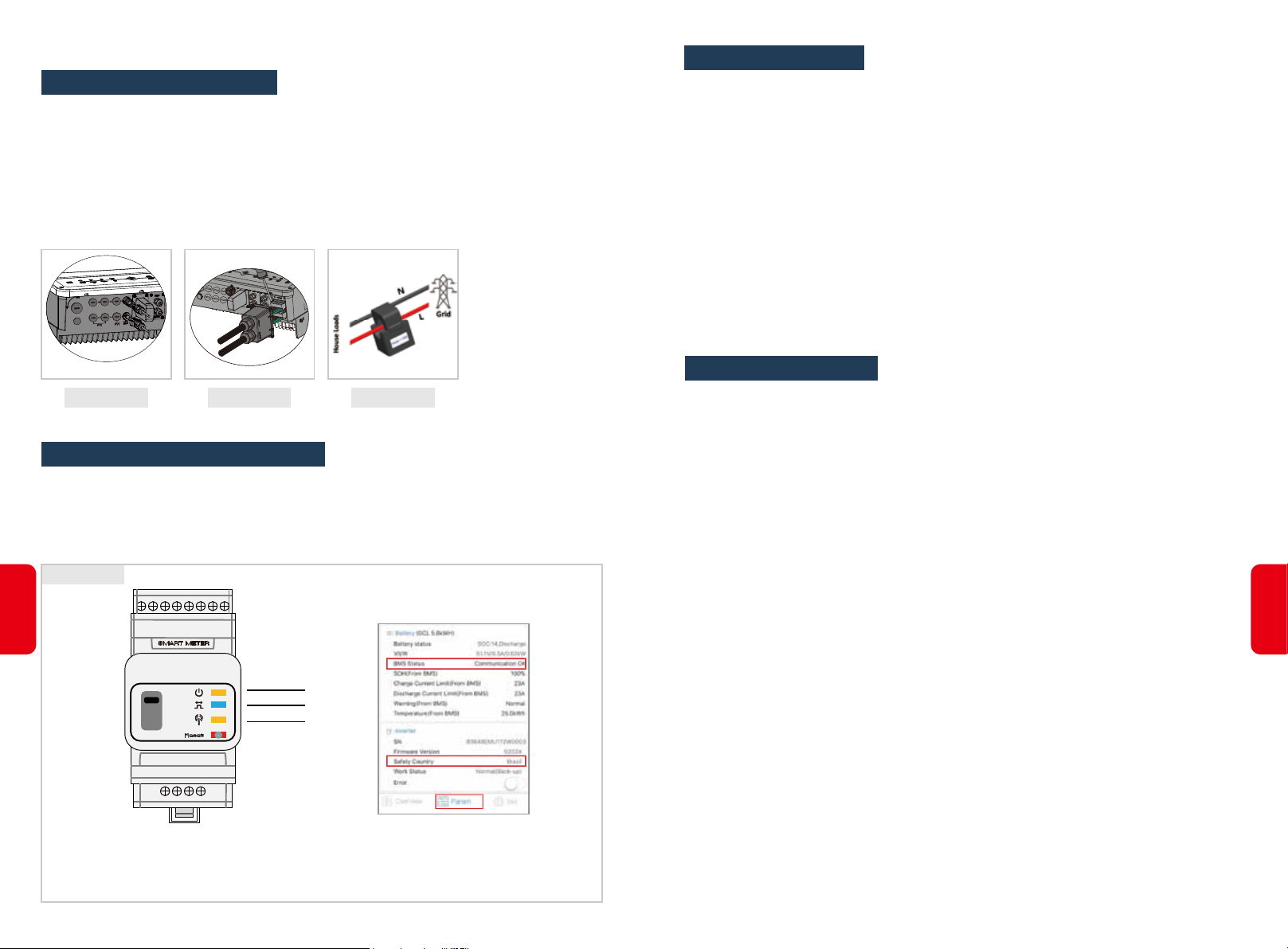
• TROUBLE SHOOTINGS
Checking Before Turning On AC power
• Battery Connection: Confirm the connection between BT and battery : polarities ( +/-) not
reversed, refer to Figure 4.1-1
• On-Grid & Back-Up Connection: Confirm ON-GRID connected to power grid and Back-Up to
loads: polarity (L1/L2/L3/N) not reversed, refer to Figure 4.1-2.
• Smart Meter & CT Connection: Make sure Smart Meter & CT are connected between house
loads and grid, follow the Smart Meter direction sign on CT, refer to Figure 4.1-3.
Problems During Operation
BT not Start Up With Only Battery
Solution:
Make sure the voltage of battery is higher than 180V, otherwise battery cannot start BT up
High Power Fluctuation on Battery Charge or Discharge:
Solution:
Check if there is a fluctuation on load power.
Battery Does Not Charge:
Solution:
1. Make sure BMS communication is OK on PV Master.
2. Check if CT connected in the right position and to right direction as on the user manual page 12
3. Check if the total load power is much higher than PV power.
Operation & Answers (Q & A)
Figure 4.1-1 Figure 4.1-2 Figure 4.1-3
Checking as Start BT up and Turn On AC power
• Battery Settings, BMS Communication and Safety Country: After connecting Solar-WiFi*
(* means the last 8 characters of the inverter serial No.), check on PV Master APP Param to make
sure battery type is right what you have installed, and Safety Country is right. If not, please set it right
in “Set” .(Figure 4.1-4)
Figure 4.1-4
21
POWER
ENERGY
COM
Note:
For compatible lithium batteries, BMS status is "communication OK" after
selecting the right battery company.
About Wi-Fi Configuration
Q: Why cannot see Solar-WiFi* signal on mobile devices
A: Normally Solar-WiFi* signal could be searched right after inverter powered up. But Solar-WiFi
signal will disappear when BT connected to internet. If need to change settings, can connect to the
router to change. If cannot see Wi-Fi signal even not connect to router, then please try to reload
Wi-Fi (please refer to BT user manual page 17).
Q: Why cannot connect Solar-WiFi* signal on my phone?
A: It is the character of the Wi-Fi module that it can connect to only one device at a time. If the signal
is connected to another device at the time for some reason, then you cannot connect to the signal.
About Battery Operation
Q: Why battery does not discharge when grid is not available, while it discharges normally when
grid is available?
A: On APP, Off-Grid output and Back-Up function should be turned on to make battery discharge
under Off-Grid mode.
Q: Why there is no output on Back-Up side?
A: For Back-Up supply, the “Back-Up Supply” on PV Master App must be turned on. Under Off-Grid
mode or grid power is disconnected, “Off-Grid Output Switch” function must be turned on as well.
Note: As turn “Off-Grid Output Switch” on, don’t restart inverter or battery, otherwise the function will
switch off automatically.
Q: On Portal, why battery SOC has a sudden jump up to 95%?
A: This normally happens on when BMS communication fail on lithium. If battery enter float charge,
SOC will be reset to 95% compulsively.
22
Page 14

Q: Why battery cannot be fully charged to 100%?
A: Battery will stop charge when battery voltage reaches charge voltage set on PV Master APP.
Q: Why battery switch always trip when starts it up (Lithium battery)?
A: The switch of lithium battery normally trips for following reasons:
1. BMS communication fails.
2. Battery SOC is too low, battery trips to protect itself.
3. An electrical short-cut happened on battery connection side. Or other reasons please contact
GoodWe for details.
Q: Which battery should I use for BT?
A: For BT series inverter, it could connect lithium batteries which have compatibility with BT series
inverter with nominal voltage from 180V to 600V. Compatible lithium batteries can see on battery
list in PV Master APP .
About PV Master Operation and Monitoring
Q: Can I use other brand Meter to take over Smart Meter in BT system or change some settings
on Smart Meter?
A: No, because the communication protocol is inset between inverter and Smart Meter, other brand
Meter cannot communicate. Also any manual setting change could cause Meter communication
failure.
Q: What is the max current allowed going through CT on Smart Meter?
A: The max current for CT is 120A.
Other Questions
Q: Is there a quick way to make the system work?
A: The shortest way, please refer to BT QUICK INSTALLATION INSTRUCTIONS and PV MASTER
APP INSTRUCTION.
Q: What kind of load can I connect on Back-Up side?
A: Please refer to user manual on page 12.
Q: Why Cannot save settings on PV Master App
A: This could be caused by losing connection to Solar-WiFi *.
1. Make sure you connected Solar-WiFi* (make sure no other devices connected) or router (if
connected Solar-WiFi* to router) and on APP home page shows connection well.
2. Make sure restart inverter 10mins later after you do some settings because inverter will save
settings every 10 mins under normal mode. We recommend you change setting parameters
when inverter under waiting mode.
Q: On the App, why the data on the homepage and Param page is different, like charge/dis-
charge, PV value, load value or grid value?
A: As the data on APP is from inverter and on home page and Param page, the data refresh frequency
is different, so there will be a data inconformity between different pages on APP as well as between
that on portal and APP .
23
Q: On App, some columns show NA, like battery SOH, etc. why is that?
A: NA means App does not receive data from inverter or server, normally it is because communica-
tion problem, such as battery communication, and communication between inverter and the APP.
About Smart Meter and Power Limit Function
Q: How to Act Output Power Limit function?
A: For BT system, the function could be realized by:
1. Make sure Smart Meter connection and communication well.
2. Turn on Export Power Limit function and set the max output power to grid on APP.
Note: If out-put power limit set as 0W,then there might still have deviation max 100W exporting to grid.
Q: Whether the warranty of the inverter still valid if the installation or operation does not follow
the user manual instructions, for some special conditions when we cannot 100% follow them?
A: Normally if any problem caused by disobeys the instructions on user manual, we can provide
technical support to help to solve the problem, but cannot guarantee a replacement or returns. So
if there is any special conditions when you cannot 100% follow the instructions, please contact
GoodWe for suggestions.
24
Q: Why there is still power exporting to grid after I set power limit as 0W?
A: Export limit could theoretically to minimum 0W, but there will have a deviation of around 50-100W
for BT system.
Page 15
4.2 DISCLAIMER
The BT series inverters are transported, used and operated under environmental and electrical
conditions. GoodWe has the right not providing after-sales services or assistance under following
conditions:
• Inverter is damaged during transferring.
• Inverter is out of warranty year and extended warranty is not bought.
• Inverter is installed, refitted or operated in improper ways without authority from GoodWe.
• Inverter is installed or used under improper environment or technical condition mentioned in this
user manual, without authority from GoodWe.
• Installation or configuration of the inverter does not follow requirements mentioned in this user
manual.
• The inverter is installed or operated against the requirements or warnings that are mentioned in this
user manual.
• Inverter is broken or damaged by any force majeure like lightening, earthquake, fire hazard, storm
and volcanic eruption etc.
• Inverter is disassembled, changed or updated on software or hardware without authority from
GoodWe.
• Inverter is installed, used or operated against any related items in international or local policies or
regulations.
• Any non-compatible batteries, loads or other devices connected to BT system.
Note: GoodWe will keep right to explain all the contents in this user manual. To insure IP65, inverter must
be sealed well, please install the inverters in one day after unpacking, otherwise please seal all
unused terminals/holes, not allowed to keep any terminals/holes open, confirm there is no risk to
have water & dust in.
Maintemamce
The inverter requires periodically maintenance, details as below:
• Make sure inverter is totally isolated from all DC and AC power for at least 5 mins before mainte-
25
nance.
• Heat sink: Please use clean towel to clean up heat sink once a year.
• Torque: Please use torque wrench to tighten AC and DC wiring connection once a year.
• DC breaker: Check DC breaker regularly, active the DC breaker 10 times in a row once a year.
• Operating DC breaker will clean contacts and extend lifespan of DC breaker.
• Water-proof covers: Check if water-proof covers of RS485 and other part are replaced once a year.
4.3 TECHNICAL PARAMETERS AND CERTIFICATES
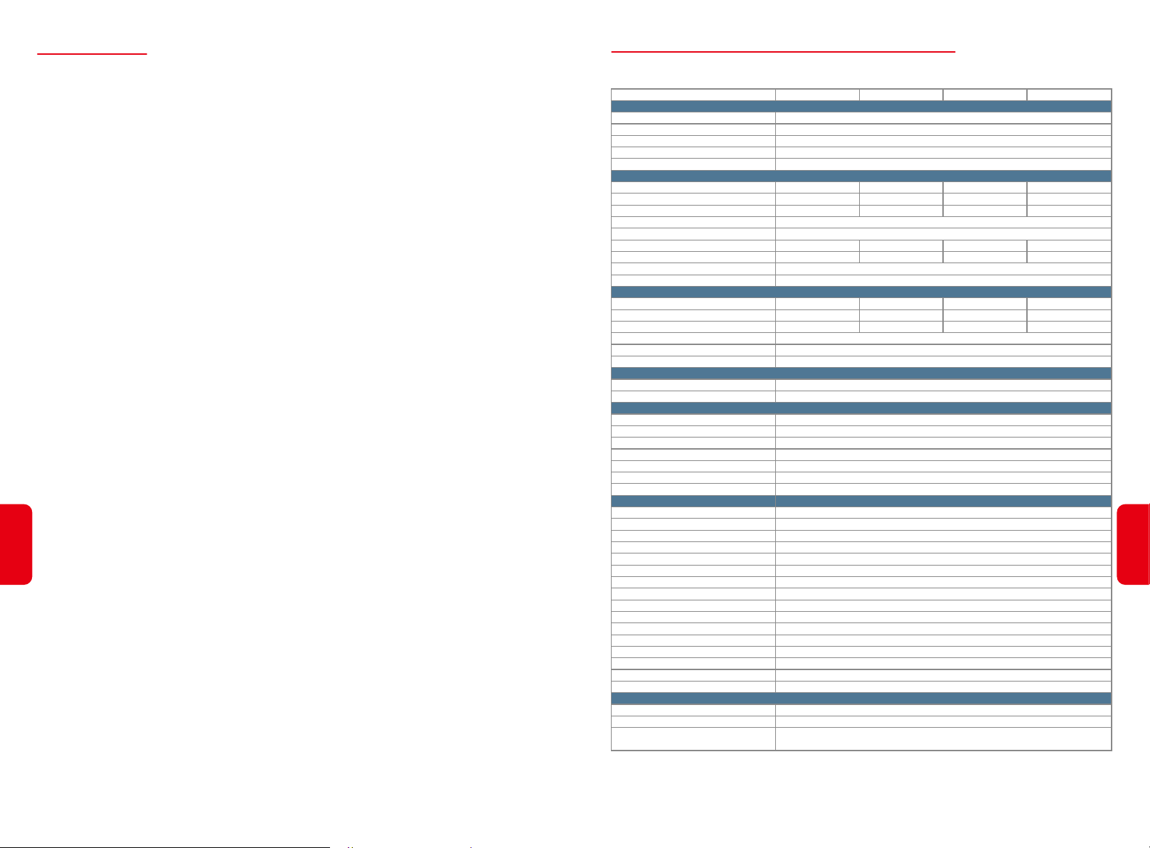
• TECHNICAL PARAMETERS OF BT INVERTERS
Technical Data
Battery Input Data
Battery Type
Battery Voltage Range (V)
Max. Charging Current (A)
Max. Discharging Current (A)
Charging Strategy for Li-Ion Battery
AC Output Data (On-grid)
Nominal Apparent Power Output to Utility Grid (VA)
Max. Apparent Power Output to Utility Grid (VA) *
Max. Apparent Power from Utility Grid (VA)
Nominal Output Voltage (V)
Nominal Output frequency (Hz)
Max. AC Current Output to Utility Grid (A)
Max. AC Current From Utility Grid (A)
Output Power Factor
Output THDi (@Nominal Output)
AC Output Data (Back-up)
Max. Output Apparent Power (VA)
Peak Output Apparent Power (VA) **
Max. Output Current (A)
Nominal Output Voltage (V)
Nominal Output Frequency (Hz)
Output THDv (@Linear Load)
Efficiency
Max. Battery to Load Efficiency
Max. Charge Efficiency
Protection
Anti-islanding Protection
Insulation Resistor Detection
Residual Current Monitoring Unit
Output Over Current Protection
Output Short Protection
Battery Input Reverse Polarity Protection
Output Over Voltage Protection
General Data
Operating Temperature Range (℃)
Relative Humidity
Operating Altitude (m)
Cooling
Noise (dB)
User Interface
Communication with BMS
Communication with Meter
Communication with EMS
Communication with Portal
Weight (kg)
Size (Width*Height*Depth mm)
Mounting
Protection Degree
Standby Self Consumption (W) ****
Topology
Certifications & Standards
Grid Regulation
Safety Regulation
EMC
GW5K-BT
5000
5500
10000
8.5
15.2
5000
10000, 60sec
8.5
* According to the local grid regulation
** Can be reached only if battery capacity is enough, otherwise will shut down.
*** CAN communication is configured by default. If 485 communication is used, please replace the corresponding communication line.
**** No Back-up Output
GW6K-BT
Self-adaption to BMS
6000
6600
12000
400/380, 3L/N/PE
10.5
18.2
~1 (Adjustable from 0.8 leading to 0.8 lagging)
6000
12000, 60sec
10.5
Nature Convection
RS485; CAN(***)
RS485 (Insulated)
516*415*180
Wall Bracket
Transformerless
CEI 0-21; VDE-AR-N 4105; G98/1; G100; EN 50438
IEC/EN 62477
EN61000-6-1, EN61000-6-2, EN61000-6-3, EN61000-6-4,
EN61000-4-16, EN61000-4-18, EN61000-4-29
Li-Ion
180~600
25
25
50/60
<3%
400/380
50/60
<3%
97.6%
97.6%
Integrated
Integrated
Integrated
Integrated
Integrated
Integrated
Integrated
-35~60
0~95%
≤4000
<30
LED & APP
RS485
Wi-Fi;LAN
21
IP65
<15
GW8K-BT
8000
8800
15000
13.5
22.7
8000
15000, 60sec
13.5
GW10K-BT
10000
11000
15000
16.5
22.7
10000
15000, 60sec
16.5
26
Page 16
• CERTIFICATES OF BT SERIES
Moisture Location Category Definition
Moisture Parameters
3K3
Level
4K3
4K4H
G100 CEI 0-21 VDE 0126-1-1 VDE-AR-N 4105 EN 50438
• OTHER TEST
For Austrlia requirements, in the THDi test, there should add Zref between inverter and mains.
RA, XA for Line conduvtor
RN, XN for Neutral conductor
Zref:
RA=0, 24; XA=j0,15 at 50Hz;
RN=0, 16; XN=j0,10 at 50Hz
4.4 WARNING QUICK CHECK LIST
[1] Inverter cannot be installed near flammable, explosive or strong electro-magnetic equipment, page 06
[2] Remember that this inverter is heavy! Please be careful when lifting out from the package, page 07
[3] Make sure battery breaker is off and battery nominal voltage meet BH specification before connecting
battery to inverter and make sure inverter is totally isolated from PV and AC power, page 09
[4] Make sure inverter is totally isolated from any DC or AC power before connecting AC cable, page 11
[5] Make sure AC cable is totally isolated from AC power before connecting Smart Meter & CT, page 13
Appendix Protection Category Defintion
Overvoltage Category Definition
27
Category I
Category II
Category III
Category IV
Applies to equipment connected to a circuit where measures have been taken
to reduce transient overvoltage to a low level.
Applies to equipment not permanently connected to the installation. Examples
are appliances, portables tools and other plug-connected equipment.
Applies to a fixed equipment downstream and including the main distribution
board. Examples are switchgear and other euiquipment in an industrial
installation.
Applies to equipment permanently connected at the origin of an installation
(uostream of the main distribution board). Examples are electricity meters,
primary over-current protection equipment and other equipment connected
directly to outdoor open lines.
Temperature Range
Moisture Parameters
Environment Category Definition
Environment Condition
Outdoor
Indoor Unconditioned
Indoor conditioned
Pollution Degree Definition
Pollution Degree I
Pollution Degree II
Pollution Degree III
Pollution Degree IV
0~+40℃
5%~85%
Ambient Termperature
-20~50℃
-20~50℃
0~40℃
No pollution or only dry, non-conductive polllution occurs. The
pollution has no influence.
Normally only non-conductive pollution occurs. Occasionally,
however, a temporary conductivity caused by condensation must
be expected.
Conductive pollution occurs, or dry. non-conductive pollution
occurs, which becomes conductive due to condensation, which is
expected.
Persistent conductive pollution occurs, for example, the
pollution caused by conductive dust, rain and snow.
-33~+40℃
15%~100%
Relative Humidity
4%~100%
5%~95%
5%~85%
~20~+55℃
4%~100%
Applied to
PD3
PD3
PD2
28
 Loading...