

Page 1
APP (iOS)Official Website APP (Android)
340-00043-02 Version: 1.0
BP SERIES USER MANUAL
DC-COUPLED BATTERY STORAGE RETROFIT
No.189 Kun Lun Shan Road, SND, Jiangsu, China.
www.goodwe.com
Jiangsu GoodWe Power Supply Technology Co.,Ltd
Page 2

TABLE OF CONTENTS
021.2 SAFETY & WARNINGS
041.3 PRODUCT OVERVIEW
011.1 OPERATION MODES INTRODUCTION
INTRODUCTION
01
052.1 UNACCEPTABLE INSTALLATIONS
052.2 PACKING LIST
062.3 MOUNTING
062.3.1 SELECT MOUNTING LOCATION
072.3.2 MOUNTING
082.4 ELECTRICAL WIRING CONNECTION
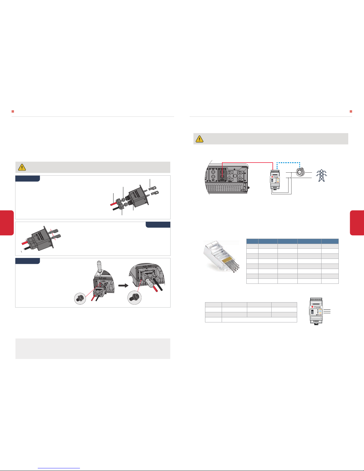
082.4.1 PV INPUT AND TO INVERTER CONNECTION
092.4.2 BATTERY CONNECTION
102.4.3 SMART METER & CT CONNECTION
INSTALLATION INSTRUCTIONS
02
133.1 WIFI CONFIGURATION
143.2 LCD DISPLAY INSTRUCTION
153.3 PV MASTER APP OPERATION
MANUAL OPERATION
03
154.1 ERROR MESSAGE AND TROUBLESHOOTING
204.2 DISCLAIMER
204.3 WARINING QUICK CHECK LIST
214.4 TECHNICAL PARAMETERS AND CERTIFICATES
OTHERS
04
TABLE OF CONTENTS
Page 3
1.1 OPERATION MODES INTRODUCTION
The BP series hybrid converters of Jiangsu GoodWe Power Supply Technology Co., Ltd. (hereinafter
called as GoodWe) strictly comply with related safety rules for product design and testing.
Please read and follow all the instructions and cautions on the hybrid converter or user manual during
installation, operation or maintenance, as any improper operation might cause personal or property
damage.
GoodWe BP series Hybrid converter is used to upgrade a single-phase grid-tied solar system into
energy-storage system with battery, thus to improve self-consumption greatly.
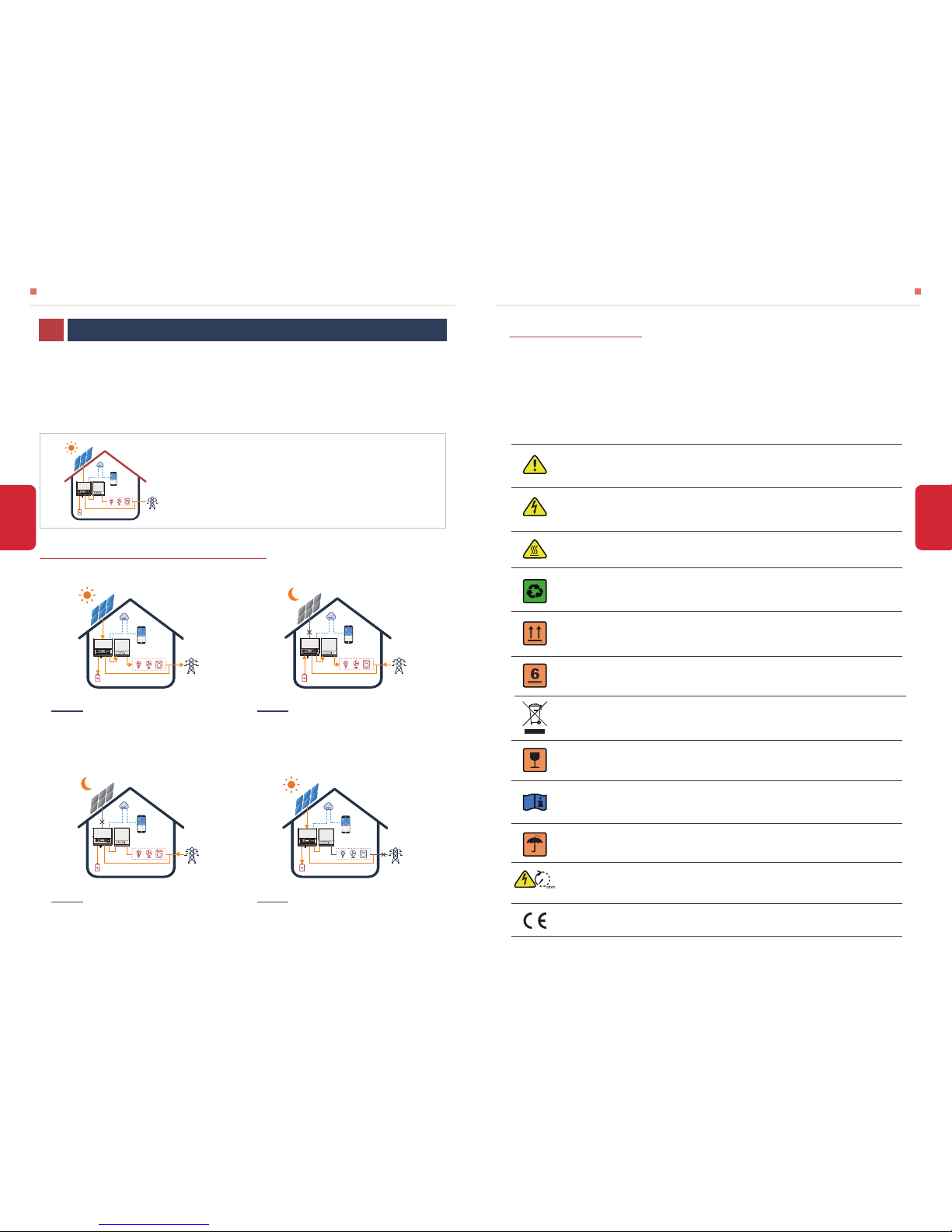
During daytime, PV panels generation can go to grid-tied inverter to support local loads, exceed
power will charge battery via BP. During night time, battery discharge to grid-tied inverter via BP to
make the whole system work without PV power.
The Hybrid converter has the following main operation modes based on different conditions:
1.2 SAFETY & WARNING
• SYMBOLS EXPLANATION
INTRODUCTION01
Caution!
Failing to observe a warning indicated in this manual may result in injury.
Danger of high voltage and electric shock!
Components of the product can be recycled.
This side up! The package must always be transported, handled and stored in such a
way that the arrows always point upwards.
Danger of hot surface!
No more than six (6) identical packages being stacked on each other.
Product should not be disposed as household waste.
The package/product should be handled carefully and never be tipped over or slung.
Refer to the operating instructions.
Keep dry! The package/product must be protected from excessive humidity and must
be stored under cover.
Inverter will be touchable or operable after minimum 5 minutes of being turned off or
totally disconnected, in case of any electrical shock or injury.
CE Mark
Note: the introduction describes a general behavior of BP system.
The operation mode can be adjusted on GoodWe PV Master APP
depends on the system layout. Below are the general operation
modes for BP system
02
INTRODUCTION INTRODUCTION
01
PV power support local loads via grid-tied inverter first,
then charge battery via BP, exceed power could be
exported to public grid
Mode Ⅰ
Battery can discharge to support the whole system
together with grid when PV power is low or without PV
power
Mode Ⅱ
Grid could support to power on BP, decrease battery
power consumption
Mode Ⅲ
When grid shut down or grid-tied inverter fails, PV
power could be used to charge battery
Mode Ⅳ
Page 4

INTRODUCTION
• SAFETY WARNING
Any installation and operation on hybrid converter must be performed by qualified electricians, in
compliance with standards, wiring rules or requirements of local grid authorities or companies (like AS
4777 andAS/NZS 3000 in Australia).
Before any wiring connection or electrical operation on hybrid converter, all DC and AC
power must be disconnected from hybrid converter for at least 5 minutes to make sure it is
totally isolated to avoid electric shock.
The temperature of hybrid converter surface might exceed 60℃ during working, so please
make sure it is cooled down before touching it, and make sure the hybrid converter is
untouchable for children.
Appropriate methods must be adopted to protect hybrid converter from static damage. Any
damage caused by static is not warranted by GoodWe.
Appropriate methods must be adopted to protect inverter from static damage. Any damage
caused by static is not warranted by GoodWe.
PV modules used on the hybrid converter must have an IEC61730 class A rating, and the total
open-circuit voltage of PV string/array is lower than the maximum rated DC input voltage of the
hybrid converter. Any damage caused by PV over-voltage is beyond warranty
Usage and operation of the hybrid converter must follow instructions in this user manual,
otherwise the protection design might be useless and warranty for the hybrid converter will be
invalid.
PV negative (PV-) on hybrid converter side is not grounded as default design.
03
INTRODUCTION
Battery Terminals
Wi-Fi Box
Reserved
RS485
Meter
PV Input Port
DC Output Port
BMS Communication Cable
Smart Meter Communication Cable
Exhaust Valve
LED Lable
WiFi Reset/Reload Button
1.3 PRODUCT OVERVIEW
04
To Battery
To Smart Meter
To Grid
Grid Connector Cable
Page 5
2.1 UNACCEPTABLE INSTALLATIONS
2.2 PACKING LIST
INSTALLATION INSTRUCTIONS INSTALLATION INSTRUCTIONS
05 06
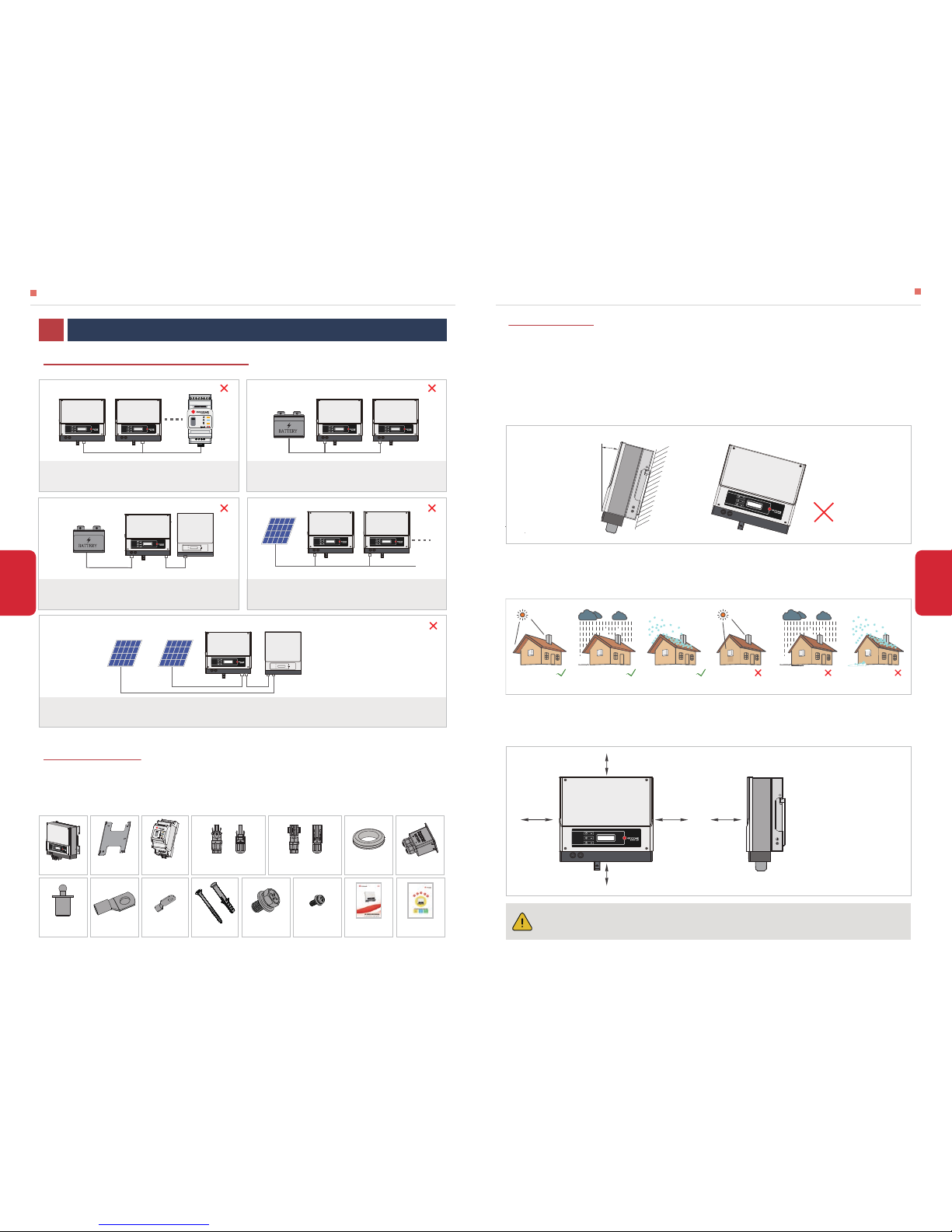
On receiving the hybrid converter, please check to make sure all the components as below are not
missing orbroken.
ONE SMART METER CANNOT CONNECT TO MULTI -INVERTERS
ONE BATTERY BANK CANNOT BE CONNECT TO
MULTI- INVERTERS.
CANNOT CONNECT TO INCOMPATIBLE BATTERIES OR
GRID-TIED INVERTERS
2.3.1 SELECT MOUNTING LOCATION
2.3 MOUNTING
Rule 1. Converter should be installed on a solid surface, where is suitable for inverter’s dimensions
and weight.
Rule 2. Converter installation should stand vertically or lie on a slop by max 15° (Pic 1)
Rule 3. Ambient temperature should be lower than 45℃
Rule 4. The installation of converter should be protected under shelter from direct sunlight or bad
weather like snow, rain, lightning etc. (Pic 2)
Rule 5. Converter should be installed at eye level for convenient maintenance.
Rule 6. Product label on inverter should be clearly visible after installation.
Rule 7. Leave enough space around converter following the values on pic 3.
Direct Sunlight Exposure to Rain Exposure to SnowNo Direct Sunlight No Exposure to Rain No Exposure to Snow
Pic 2
Upward----------
Downward------
Front-------------
Both sides-------
300mm
500mm
300mm
200mm
300mm
300mm
200mm
200mm
500mm
Pic 3
Converter cannot be installed near flammable, explosive or strong electro-magnetic
equipment.
[1]
Pic 1
For converter’s protection and convenient maintenance, mounting location for converter should be
selected carefully based on the following rules:
INSTALLATION INSTRUCTIONS02
Battery terminal × 2 PE terminal × 1 Expansion bolts×6
Hexagon head
screw × 2
Pan head
screw × 12
User manual×1
Quick Installation
Guide×1
Battery
Incompatible battery
SINGLE MPPT GRID-TIED INVERTER, WITH TWO DC INPUTSTHE SEPARATE STRINGS CANNOT BE CONNECTED AS SHOWN
SINGLE PV STRING CANNOT CONNECT TO TWO OR
MORE INVERTERS.
PV PV
Smart Meter
Battery Battery
15°
Single-MPPT Two DC
input Grid-tied Inverter
Battery cover × 1
Insulation ring×2
Smart Meter
& CT × 1
Converter×1
Wall-mounted
Bracket×1
Positive
DC Plug×2
or
Negative
DC Plug×2
or
Waterproof
terminal×1
Page 6
The converter is suitable for mounting on concrete or other non-combustible surface only
INSTALLATION INSTRUCTIONS INSTALLATION INSTRUCTIONS
07 08
2.3.2 MOUNTING
Remember that this converter is heavy! Please be careful when lifting out from the package.
[2]
NOTE: Bearing capacity of the wall must be higher
than 8KG, otherwise may not be able to keep
converter from dropping.
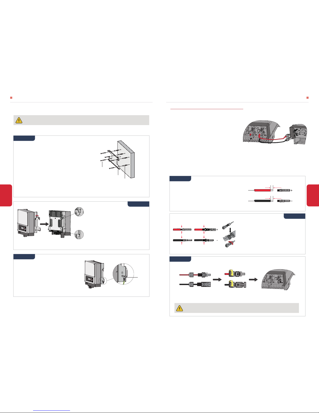
• Please use the mounting bracket as a template to
drill 6 holes on right positions (10mm in diameter,
and 80mm in depth) (Pic 4)
• Use expansion bolts in accessory box and fix the
mounting bracket onto the wall tightly
Step 1
Pic 4
Step 3
Ground cable shall be connected to ground
plate on grid side (Pic 6)
Pic 6
2.4 ELECTRICAL WIRING CONNECTION
2.4.1 PV INPUT AND TO INVERTER CONNECTION
1. A DC breaker must be installed between PV
panels and BP converter. And make sure the DC
breaker is turned off before connecting PV to BP
converter.
Please follow the following rules when connecting
PV panels to BP converter:
2. The short-circuit current and open-circuit voltage of PV string must not exceed the Max DC
Current and Max Input Voltage of BP converter
3.PV strings could not connect to earth/grounding conductor and the minimum isolation resistance
to ground of PV strings must exceed 18.33KΩ
There could be SUNCLIX, MC4 or Amphenol DC plugs in accessory box
Step 2
Carry the converter by holding the heating
sink on two sides and Place the converter
on the mounting bracket. (Pic 5)
NOTE: Make sure the heat sink on converter
is rightly joint with mounting bracket.
Pic 5
Detail b
Detail a
PE terminal
Hybrid Converter
From PV Panels
To Solar Inverter
PV﹢
PV﹣
Solar Inverter
Connect PV cable to DC connectors (Pic 8)
NOTE:
• Please use DC plugs and connectors in
GoodWe accessory box
• PV cable should be standard, 2.5-4mm
2
PV
cable
NOTE:
• PV cable must be tightly crimped into the
connectors
• For Amphenol connector, the limit buckle
cannot be pressed
Prepare PV cables and DC plugs (Pic 7)
MC4 series
AMPHENOL series
SUNCLIX
2.5-4mm²
7mm
2.5-4mm²
7mm
Pic 7
Pic 8
Step 1
Step 2
Step 2
The polarity of PV strings or on the converter cannot be connected by reverse,
otherwise converter could be damaged.
[3]
Screw the cap on and plug onto inverter side (Pic 9)
Pic 9
Step 3
NOTE:
• There will be a click sound if connectors are inset correctly into DC plugs
self-tapping screws
Wall bracket
Expansion pipe
Page 7
09
Battery will act a protective charge/discharge current limitation under any condition as below:
• BATTERY PROTECTION DESCRIPTION
• Battery SOC is lower than 1-DOD
• Battery voltage lower than discharge voltage
• Battery communication abnormal for lithium battery
• BMS limitation for lithium battery
• Battery over temperature protection
• Please be careful against any electric shock or chemical hazard
• Lithium battery (pack) the capacity should be ≥50Ah. Lead acid batteries are not allowed to use
with BP converter without GoodWe's authority.
• Make sure there is an external DC switch (≥63A) connected for battery without attached DCswitch
2.4.2 BATTERY CONNECTION
* For the compatible lithium batteries connection, please refer to battery connection part in BP
QUICK INSTALLATION INSTRUCTIONS.
Battery wiring connection steps as below:
Make sure battery switch is off and battery nominal voltage meet BP specification beforeconnecting battery to converter make sure converter is totally isolated from PV and AC power
[4]
.
NOTE:
1. Please use accessories from GoodWe box
2. Battery power cable should be 20-25 mm²
Prepare battery cables and accessories and put
battery power cable through battery cover (Pic 10 )
Battery Terminal
Waterproof Ring
Screw Cap
Insulator
Cable
Pic 10
Step 2
Make battery terminals (Pic 11)
• Strip cable coat, revealing10mm length of metal core
• Use special crimper to compress battery terminal tightly
Use Special Tool to Crimp
Pic 11
NOTE: Please make sure polarity (+/-) of
battery are not reversed
Connect battery terminals onto
converter (Pic 12)
Pan Head Screw
Hexagon Head Screw
Fastening torsion 6-8N.m
Pic 12
Step 1
Step 3
10
INSTALLATION INSTRUCTIONS INSTALLATION INSTRUCTIONS
NOTE:
1. The Smart Meter and CT is well configured, please do not change any setting on Smart Meter
2. CT must be connected on the same phase with Smart Meter power cable
2.4.3 SMART METER & CT CONNECTION
• Single-Phase Smart Meter Wiring (Pic 13)
• Detailed pin function of each port on BP converter is as below:
Make sure AC cable is totally isolated from AC power before connecting Smart Meter and CT
[6]
10m 2m
Smart Meter
House
House→Grid CT
N
L
Pic 13
Color BMS Function Smart Meter Function
Orange NC NC
Orange&white 485_A2 NC
Green&white 485_B2 485_B1
Blue CAN_H NC
Blue&white CAN_L NC
Green NC 485_A1
Brown&white NC 485_B1
Brown
Position
2
1
3
4
5
6
7
8 NC 485_A1
RS485
485_B
485_A
485_A
NC
NC
485_B
NC
NC
Pic 14
NOTE:
For both Smart Meter, customer can also check on PV Master App
• Single-Phase Smart Meter LED Indications
05
OFF Blinking
ENERGY / Exporting
POWER Not working /
COM Blink one time when it transfer data to inverter
ON
Importing
Working
ENERGY
POWER
COM
9 10
Page 8
12
11
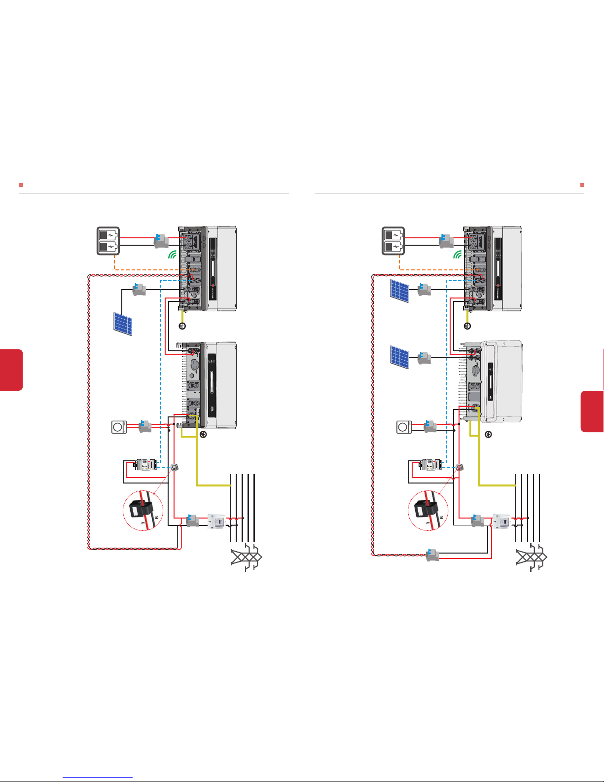
• WIRING SYSTEM FOR BP CONVERTER
1.DC Breaker is compulsive, or DC power can not be cut off manually
2.Direction of the CT cannot be connected in reverse, please follow “House→Grid” direction to do the connection
3.Only for lithium battery which has BMS communication
INSTALLATION INSTRUCTIONS
MAMUAL OPERATION
1.DC Breaker is compulsive, or DC power can not be cut off manually
2.Direction of the CT cannot be connected in reverse, please follow “House→Grid” direction to do the connection
3.Only for lithium battery which has BMS communication
4.AC Breaker is optional or shut AC power off if you need close BP converter
To INVERTER connection
CT*
2
ON-Grid Load
Grid
To lithium battery*
3
Dual-MPPT Two DC
input Grid-tied inverter
Power Meter
PV Strings
Battery
9 10
L1L2L3
N
PE
L
N
Grid
House
→
Grid
House→Grid
DC Breaker
≥63A
DC Breaker
*
1
PV Strings
DC Breaker
AC Breaker
*
4
• WIRING SYSTEM FOR BP CONVERTER
To INVERTER connection
CT*
2
ON-Grid Load
Grid
To lithium battery*
3
Single-MPPT One DC
input Grid-tied-inverter
Power Meter
PV Strings
Battery
9 10
L1L2L3
N
PE
L
N
Grid
House
→
Grid
House→Grid
DC Breaker
≥63A
DC Breaker
*
1
Page 9
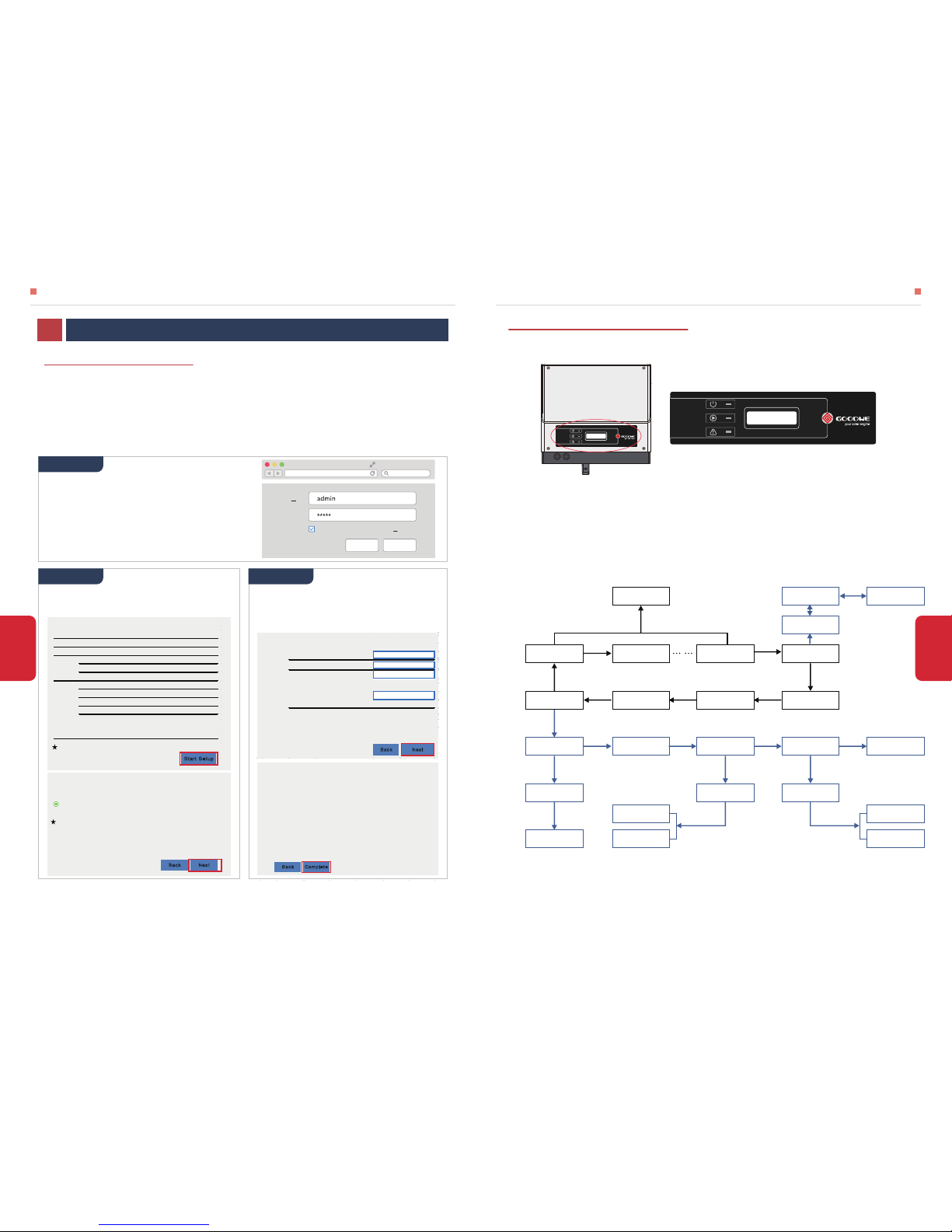
Note: Double click of the button takes display back to the last page.
LOCK
Settings
Charge Current
CHGI=50A
Charge Voltage
CHGV=57.5V
Mcter Comm OK/Fail
BMS Comm OK/Fail
VBat=50.0V
Pbat=25.2W
Languge:English
SOC=60%
Error History
Short press
Long press for 2s
Long press for 2s
Long press for 2s Long press for 2s Long press for 2s
Short press
Short press
Short press
Short press Short press Short press
Short press
Long press for 2s
Batt DisCHG Mode
Day & Night
Batt DisCHG Mode
Day & Night
Batt DisCHG Mode
Night Only
WiFi Resetting WiFi Reloading
WiFI Reset OK WiFI Reload OK
WiFI Reset Fail WiFI Reload Fail
Languge: English WiFi Reset WiFi Reload Exit
Error Code1:XX
Error Code2:XX No Error
Standby
Pbat=25.2W
14
13
• DISPLAY OPERATION MENU
LED Display
Discharge
P bat = 2499.9W
Note: All the settings except for “WiFi Reloading” and “WiFi Resetting” can also be done on GoodWe PV
Master App.
3.2 LCD DISPLAY INSTRUCTION
MAMUAL OPERATION
OTHERS
• This part shows configuration on web page
• Wi-Fi configuration is absolutely necessary for online monitoring and after-sales maintenance
NOTE:
1. Please make sure the password, Encryption Method/Algorithm is right the same with the router’s
2. If everything is right well, the Wi-Fi LED on inverter will change from double blink to quartic blink then to
solid status, which means Wi-Fi is connected to GoodWe icloud successfully.
3. Wi-Fi configuration could also be done on PV Master, details please check on PV Master APP
3.1 WIFI CONFIGURATION
MAMUAL OPERATION03
PREPARATION:
1. Inverter must be powered up with only PV power
2. Need a router with available internet access to GoodWe portal https://www.semsportal.com
1. Connect Solar-WiFi* to your PC or smart
phone(* means the last 8 characters of the
inverter serial No.)
2. Open browser and login 10.10.100.253
Admin (U): admin; Password: admin
3. Then click “OK”
1. Click “Start Setup” to choose your router
2. Then click “Next”
1. Fill in the password of the router, then click
“Next”
2. Click “Complete”
10.10.100.253
Admin(U):
Password:
OK
CANCEL
Remember the password(R)
Device informati on
Firmware verison
MAC address
Wireless AP mode
SSID
IP address
Wireless STA mode
Router SSID
Encryption method
Encryption algorithm
Router Password
Sta rt Set up
Cann ot join th e ne twor k, may be cau sed by :
router doesn't exist, or signal is too week, or password is incorrect
Help :
Wizard will help you to complete sett ing within one mimute.
1.6.9.3.38.2.1.38
60:C5:A8:60:33:E1
Ena ble
Solar-WiFi
10.10.100.253
Dis able
WiFi_Burn-in
WAP/WAP2-PSK
AES
WiFi_Burn-in
Add wireless network manu ally
Network name (SSID)
Encryption method
Encryption algorithm
Ple ase ent er t he wire less ne twor k p ass word:
Password (8-63 bytes)
show psk
Bac k Nex t
WiFi -T est
WPA/ WPA2 -PSK
AES
hell ogoo dwe
Not e: case s ensitive for SSID and password
Please make sure all parameters of wireless network are matched with router,
including password
Step 1
Step 2 Step 3
Bac k Comp lete
Confirm to complete?
If you still need to configure the other pages of information, please
go to complete your required configuration.
Click 'Complete', the current configuration will take effect after
restart.
Configuration is completed, you can log on the Management page
to restart device by Click on 'OK' button.
Save success!
Please select your cur rent wireless network:
SSID Sec mode Enc type Channel RSSI
WIFI Test WAP2-PSK AES 6 54%
Bac k Next
Note: When RSSI of the selected WiFi Network is lower than 10%, the
connection may be unstable, please select other available network or
shorten the distance between the device and the router.
If your wireless router does not broadca st SSID, please cl ick "Next" and
add a wireless network manually.
Page 10
15 16
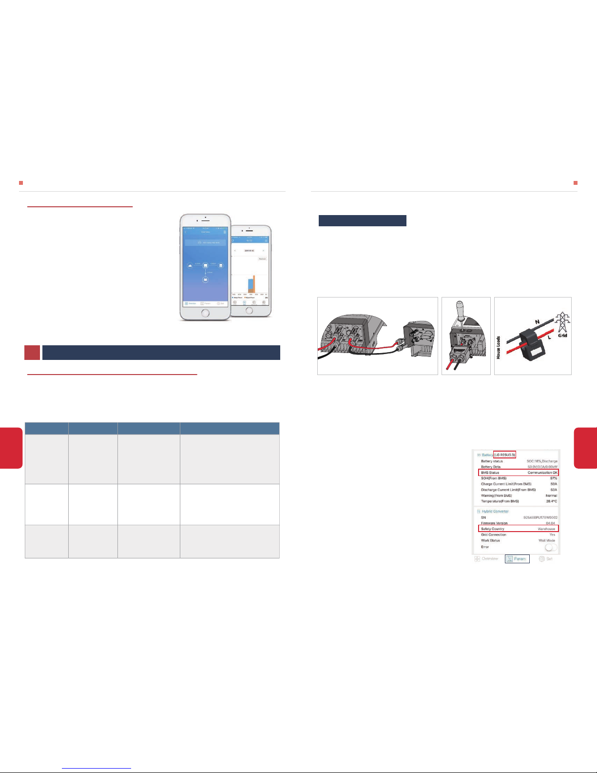
PV Master is an external monitoring/ configuration
application for GoodWe hybrid inverters, used on smart
phones or pad for both Android and iOS system, main
functions as below:
1. Edit system configuration to make the system work as
customer needs
2. Monitor and check performance of the hybrid system
3. Wi-Fi configuration
Please download PV Master OPERATION INSTRUCTIONS from www.goodwe.com
3.3 PV Master APP OPERATION
Note: All the errors about battery happen only on Lithium battery with BMS communication
• ERROR MASSAGE
4.1 ERROR MASSAGE AND TROUBLESHOOTINGS
The error massages below will be displayed onthe LCD or PV Master App or report by Email if the
error really happen
OTHERS04
ERROR MASSAGE EXPLANATION REASON SOLUTIONS
PV Over Voltage
DC total voltage of
PV string is too high
The total voltage
(short-circuit voltage) of
each PV string is
higher than the max DC
input voltage of the hybrid
converter.
Check PV string VOC is lower than Max PV Input
Voltage of the hybrid converter
If VOC of PV string is high, please decrease panels to
make sure VOC is with the max DC input voltage of
the hybrid converter.
Over Temperature
Temperature inside
of the hybrid
converter is too high
hybrid converter working
environment leads to a high
temperature condition
1. Try to decrease surrounding temperature
2. Make sure the installation complies with the
instruction on inverter user manual
3. Try to close inverter for 15 mins, then start up again.
DC Bus High
BUS voltage is
over-high
/
Try to restart hybrid converter, check if it still happens,
if not, means it is just an occasional situation or contact
GoodWe
◈ PV Input Connection: Confirm the connection between BP converter and PV panels : polarity ( +/-)
not reversed, refer to pic 15
◈ Battery Connection: Confirm the connection between BP converter and battery : polarities ( +/-)
not reversed, refer to pic 16
◈ Smart Meter& CT Connection: Make sure CT are connected between house loads and grid, and
follow the House→Grid direction sign on CT. (Pic 17)
◈ Battery Settings, BMS Communication and Safety Country:
After connecting Solar-WiFi* (* means the last 8 characters of the inverter serial No.), check on PV
Master APP (in “Param” column) to make sure battery type is right what you have installed. If not,
please change it in “Set” column (Pic 18)
For Lithium batteries, BMS status should be “Communication OK”
Note: If BMS Status says “NG”, then please make sure
battery communication cable wiring connection and all
settings are all right, refer to battery connection SOP in
S-BP QUICK INSTALLATION INSTRUCTIONS
Checking Before Starting bp Up
Pic 18
• TROUBLESHOOTINGS
OTHERS
OTHERS
Pic 17Pic 15 Pic 16
Hybrid Converter
From PV Panels
To Solar Inverter
PV﹢
PV﹣
Solar Inverter
House→Grid
(K)
(L)
Page 11

18
About others
A: Cannot can only work with grid-tied inverter without anti-recerse function activated
Q: Could BP converter work normally if the grid-tied inverter works under anti-recerse(zero
export)function?
Questions & Answers (Q & A)
About Wi-Fi Configuration
NOTE: If Wi-Fi led on inverter is single-blinking (0.5s on & off), then it means Wi-Fi module is not
connected or not connected well
A: Normally Solar-WiFi* signal can be searched after inverter powered up.
Please check if Wi-Fi module is connected well, and make sure inverter is powered up normally.
Q: Why cannot search Solar-WiFi* signal on smart phone?
NOTE: Please make sure the password of the Wi-Fi signal (12345678) is not wrong
A: It is the character of the Wi-Fi module that it can connect to only one device at a time. So please
make sure the signal is not connected on other device.
Q: Why cannot connect Solar-WiFi* signal on my mobile device?
Check items:
1.1t takes 20-30s before battery charge.
2.Check if Smart Meter&CT connected in the right position and to right direction as on the user manual;
3.Make sure PV voltage is higher than 100V to start BP up;
4.Check if total load power is much higher than PV power, or check if Pgrid on GoodWe Portal is always
below 0W.
5.Make sure PV voltage is lower than 9*Battery voltage-20V, if not, please decrease panels
If everything is OK, but problem still there, please contact GoodWe after-sales services.
NOTE: Sometime BP may be under standby status for long time, this might result from the sharp change of
PV or Load power during a short time("import/export Power" changed a lot between buy/sell power to grid,
battery cannot charge continuously)
Solution:
Battery not charge when export power>100W
Check items
1.Check if there is a fluctuation on load power;
2.Check if there is a fluctuation on PV power on GoodWe Portal.
If everything is OK,please contact GoodWe after-sales Services
Solution:
Big Power fluctuation on battery charge/discharge
Possible Problems During Operation
1.Make sure the voltage of battery is higher than 50.5V, otherwise battery cannot start BP up.lf battery
voltage is OK, but problem still there, please contact GoodWe after-sales services
Solution:
BP not start up with ONLY battery connected
1.Make sure the voltage of PV is higher than 90V;
2.Make sure the connection between BP ("TO INVERTER") and inverter is well-not reversed;
If everything is OK, but problem still there, please contact GoodWe after-sales services.
Solution:
BP not start up with ONLY PV connected
Make sure the voltage of Grid is higher than 90V, otherwise Grid cannot start BP up. lf Grid voltage is OK,
but problem still there, please contact GoodWe after-sales services
Solution:
BP not start up with ONLY Grid connected
Check Items:
1.Follow the steps as above the last trouble shooting;
2.Make sure the work mode is set to "Day and night mode".
3.Make sure PV voltage is lower than 9*Battery voltage-20V, if not, please decrease panels;
lf everything is OK, but problem still there, please contact GoodWe after-sales services.
Solution:
Import power>100W but battery does not discharge
Check items:
1.It takes 20-30s before battery discharge.
2.Communication between BP and Smart Meter is OK or not;
3.Make sure import Meter power is lower than -100W.
a.BP/battery will not discharge unless import Power is lower than 100W;
b.lf import Power is lower than 100W, but BP/Battery still not discharge, then please check Smart
meter&CT connection and direction;
4.Make sure SOC is higher than 1-DOD;Or if battery discharged to below 1-DOD, than battery will
only discharge again when 50C charged to 20%+ (1-DOD) /2 (if need battery discharge immediately,
customer can restart the system)
If everything is OK, but problem still there, please contact GoodWe after-sales services.
NOTE: sometime BP may be under standby status for long time, this might result from the sharp change of
PV or Load power during a short time("import/export Power" changed a lot between buy/sell power to grid,
battery cannot discharge continuously)
Solution:
There is no discharge or output power from BP at night time
17
OTHERS
OTHERS
Page 12

19 20
1. Day and Night mod:battery discharge when system need, nothing to do with PV voltage;
2. Night Only mode:battery discharge only when PV voltage lower than 100V.
Difference on work mode“Day and Night” modeand“ Night Only” mode
1.Open or close it on PV Master APP;
2.Used to activate battery when battery is discharged empty;
3.Only used when there is no battery voltage.
“Battery Activate” function
1.BP can ONLY charge when grid is OFF, because inverter cannot work normally without gird.
How BP works when grid is OFF
1.Meter power >+100W, battery can start to charge;
2.Meter power <-100W, battery can start to discharge;
The threshold of Meter power to charge/discharge battery
1.For LG battery, it will stop charge at SOC 95%. It is about LG battery, normal
2.Battery will also stop charge when battery voltage reaches charge voltage set on PV Master APP;
Battery SOC cannot charge to 100%
1.For lithium battery, please make sure BMS communication OK;
2.Please check if battery voltage is large than discharge voltage set on APP
3.Make sure no short-cut on Battery connection side.
Battery switch trip
NOTE: If PV power is lower than 100W, or battery cannot get effective charge from PV because of like bad
weather for long time, battery voltage will drop low till it trips.
1.Only used with single-phase on-grid inverters;
2.For each system, can only use one BP;
How BP used with on-grid inverter
1. It is used to keep system alive without using battery power when battery voltage is low (on APP,
battery voltage will show as 0V, but BMS communication OK);
2. It cannot be used to charge battery
What is the “Grid” cable on BP converter used for
NOTE: battery could still act self consume, which could still drop battery voltage if battery cannot get
charge fro long time
Lithium battery must connect BMS communication and select the right battery type on APP
Battery configuration
PV will charge battery in priority to protect battery from over-discharge when battery SOC is low and
reached the forced charging point of individual battery (forced charging point for each battery is
different)
About forced charging
4.3 WARINING QUICK CHECK LIST
[1] Converter cannot be installed near flammable, explosive or strong electro-magnetic equipment, page 6
[2] Remember that this converter is heavy! Please be careful when lifting out from the package, page 7
[3] The polarity of PV strings or on the converter cannot be connected by reverse, otherwise converter
could be damaged, page 8
[4] Make sure battery switch is off and battery nominal voltage meet BP specification beforeconnecting
battery to converter make sure converter is totally isolated from PV and AC power,page 9
[5] Make sure AC cable is totally isolated from AC power before connecting Smart Meter and CT, page 10
4.2 DISCLAIMER
The BP series hybrid converters are transported, used and operated under environmental and
electrical conditions. GoodWe has the right not providing after-sales services or assistance under
following conditions:
* Maintenance
The converter requires periodically maintenance, details as below:
NOTE: Make sure converter is totally isolated from all DC and AC power for at least 5 mins before
maintenance
Heat sink: please use clean towel to clean up heat sink once a year
Torque: please use torque wrench to tighten AC and battery wiring connection once a year
DC switch: check DC switch regularly, active the DC switch 10 times in a row once a year. operating
DC switch will clean contacts and extend lifespan of DC switch
Water-proof covers: check if water-proof covers of RS485 and other part are fasten once a year
Note: GoodWe will keep the right to explain all the contents in this user manual.
• Inverter is damaged during transferring
• Inverter is out of warranty year and extended warranty is not bought
• Inverter is installed, refitted or operated in improper ways without authority from GoodWe
• Inverter is installed or used under improper environment or technical condition mentioned in this
user manual, without authority from GoodWe
• IInstallation or configuration of the converter does not follow requirements mentioned in this user
manual
• The converter is installed or operated against the requirements or warnings that are mentioned in
this user manual
• Converter is broken or damaged by any force majeure like lightening, earthquake, fire hazard,
storm and volcanic eruption etc.
• Converter is disassembled, changed or updated on software or hardware without authority from
GoodWe
• Converter is installed, used or operated against any related items in international or local policies or
regulations
• Any non-compatible batteries, loads or other devices connected to BP system
OTHERS OTHERS
Page 13
21 22
*PV input Max. allowed voltage is 500V, But the BP really working voltage range is 100~450V;
*For Li-lon battery, charge current follows the command of BMS which doesn't exceed 50A.
*Make sure PV voltage is lower than 9*Battery voltage-20V, if not, please decrease panels.
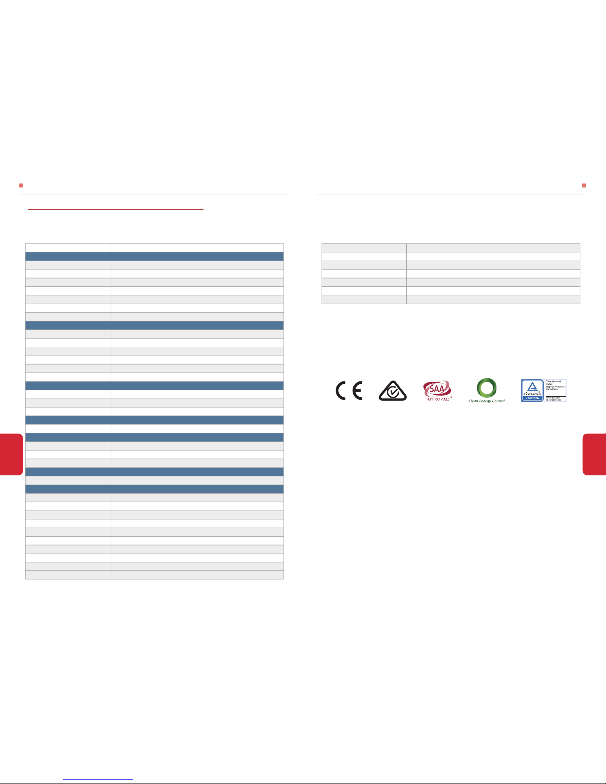
• CERTIFICATES OF BP SERIES
Topology
Standby losses(W) <8
Cooling
Noise emision(dB)
Display
Communication
Standard warranty(years)
High frequency insulation
Nature convection
<25
LCD+LED
USB2.0;WiFi
5
OTHERS OTHERS
4.4 TECHNICAL PARAMETERS AND CERTIFICATES
• TECHNICAL PARAMETERS OF HYBRID CONVERTERS
GW2500-BPModel Name
Max. allowed PV input power(W)
PV Input
Max. allowed PV input voltage (V)*
BP working voltage range(V)
Max. PV input current (A)
No. of PV input&output connectors
PV overvoltage category
PV connector
Battery
6000
500
100~450
25
1/1
Category II
AMPHENOL/MC4/SUNCLIX(Optional)
Norminal voltage (V)
Battery type
MAX Discharge/Charge current(A)*
MAX discharge/charge power(W)
Battery capacity (Ah)
Charging curve
BP output (without PV)
Rated output voltage (V)
Output voltage range (V)
2500/2500
50~1000
self-adapt to Li-lon battery BMS
360
250~360
Max output current (A) 10
Efficiency
Max. Battery efficiency 96.5%
Battery over&low voltage protectior
Integrated
Over current protection
Output short protection
Safety/EMC CE
General data
Dimensions (W×H×D) 344*274.5*128mm
Weight (kg)
Mounting
8
Ambient temperature range -25~600℃(>45℃ derating)
Wall bracket
Relative humidity
0~95%
Moisture location category
Max. operating altitude
4K4H
4000m(>3000m derating)
Protection degree
IP65
Environment category
Outdoor&indoor
External environment pollution degree
Grade1,2,3
Li-lon
50/50
Integrated
Integrated
48
Page 14

23
OTHERS
Appendix: Protection Category Definition
No pollution or only dry, non-conductive pollution occurs. The pollution has no influence
Pollution Degree Ⅰ
Normally only non-conductive pollution occurs. Occasionally, however, a temporary conductivity caused by condensation
must be expected.
Pollution Degree Ⅱ
Conductive pollution occurs, or dry, non-conductive pollution occurs, which becomes conductive due to condensation,
which is expected.
Pollution Degree Ⅲ
Persistent conductive pollution occurs, for example, the pollution caused by conductive dust, rain and snow.
Pollution Degree Ⅳ
Pollution Degree Definition
Relative Humidity Applied to
-20 ~ 50℃
Ambient Temperature
4% ~ 100% PD3Outdoor
Environment Condition
Indoor Unconditioned
Indoor Conditioned
-20 ~ 50℃
5% ~ 95%
5% ~ 85%
PD3
PD2
0 ~ 40℃
Environment Category Definition
Applies to equipment connected to a circuit where measures have been taken to reduce transient overvoltage to a low level
Category Ⅰ
Applies to equipment not permanently connected to the installation. Examples are appliances, portables tools and other
plug-connected equipment
Category Ⅱ
Applies to a fixed equipment downstream of and including the main distribution board. Examples are switchgear and other
equipment in an industrial installation
Category Ⅲ
Applies to equipment permanently connected at the origin of an installation (upstream of the main distribution board). Example
are electricity meters, primary over-current protection equipment and other equipment connected directly to outdoor open
lines
Category Ⅳ
Overvoltage Category Definition
Moisture Location Category Definition
Level
3K3 4K2 4K4H
Moisture Parameters
Humidity Range 15%~100%
Temperature Range
0~+40℃ -33~+40℃ -20~+55℃
4%~100%5%~85%
 Loading...