

Goodwe 5048ES, 5048D-ES Installation Manual

Goodwe 5048ES with BYD B-BOX (2.5-10) Installation Guide
Attention:
Goodwe 5048D-ES in this manual is the new one with serial number starting with 9 ie 95048ESU16XXXXX.
For the Goodwe 5048D-ES with starting SN 3, please refer to other document.
Index
1. Physical wiring
2. APP configuration
3. System function review
4. WiFi set up
5. Could Account Registration
6. Check List
Part 1: Inverter and battery physical connection
1.1 DC POWER connection (Battery and PV connection)
Referring to Goodwe ES manual 4.1 & 4.2 as well as BYD battery manual for physical connection
1.2 AC POWER connection
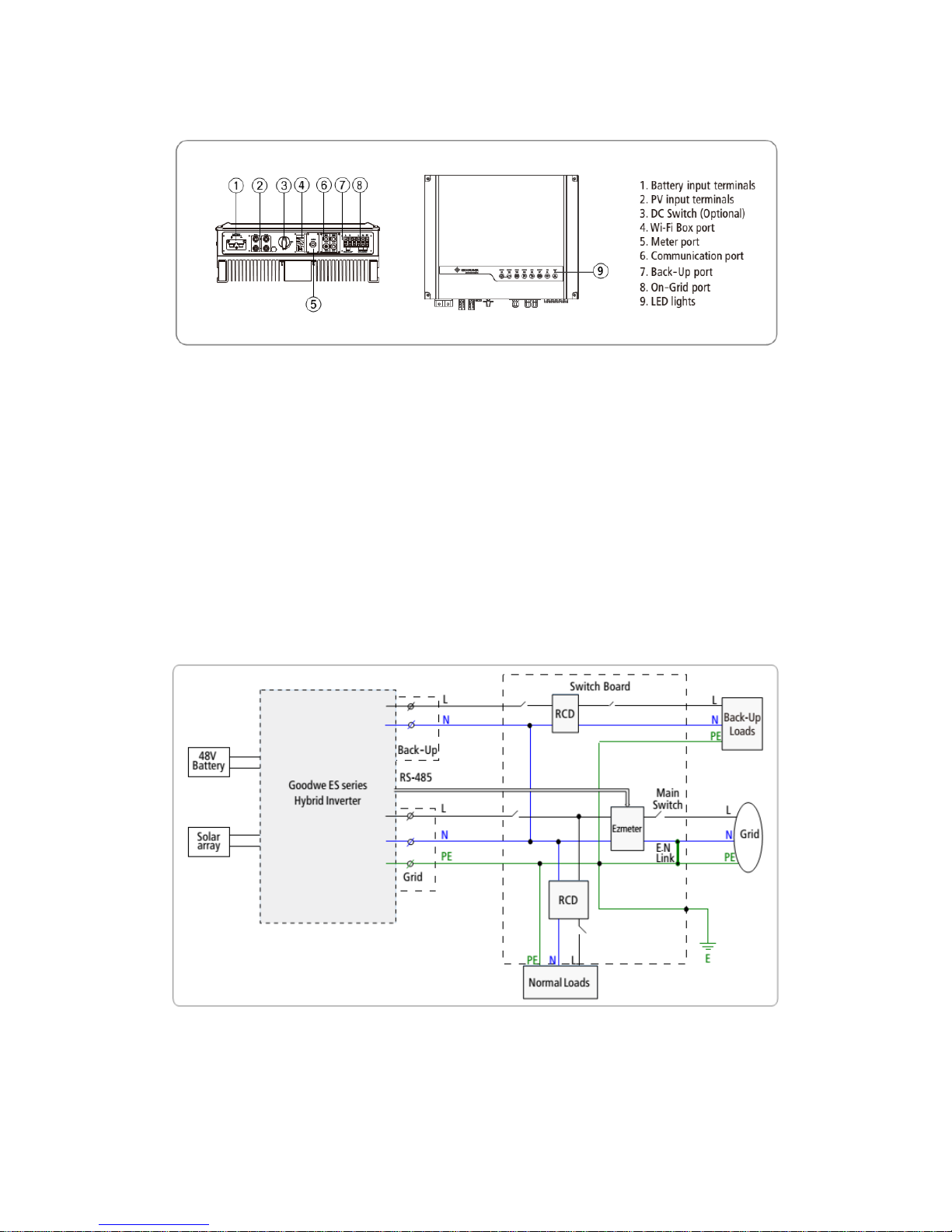
Goodwe 5048D-ES inverter has the grid connected and back up connection at the bottom of
inverter.
Customer could connect essential loads to the back up supply part so that when the grid is off,
the inverter still support back up load within 8ms.
During the grid connected condition, the inverter still recognize back up and grid tied load as
entire load, support these loads from PV, battery and grid. Even when there is no available PV
and battery, the inverter still use the grid power to support both loads.
Circuit diagram:
Attention point:
a. According to Australian Standard, when customer is using the back up load, the neutral cable
between the inverter back up part and neutral cable from grid connected part must be
jumped together. Installer can jump cables at the bottom of inverter or on the neutral bar.
b. 5048D-ES back up max power output is 4.6kW, however there is further load definition must
be compliant by using back up mode (or off grid scenario). When using the inverter as off
grid system, once the back up load is oversize, the inverter’s fault light will blinking and
inverter will shut down for self-protection.
c. Do NOT connect the grid to inverter’s back up part under any scenario. The inverter could be
damaged if there is power flows into the inverter from back up part.
d. To improve the system reliability, Goodwe recommends installer to install a changeover
switch between back up load and grid tied load. Then for rare case, if the inverter is faulty,
customer could manual switch all essential house loads back to the grid side.
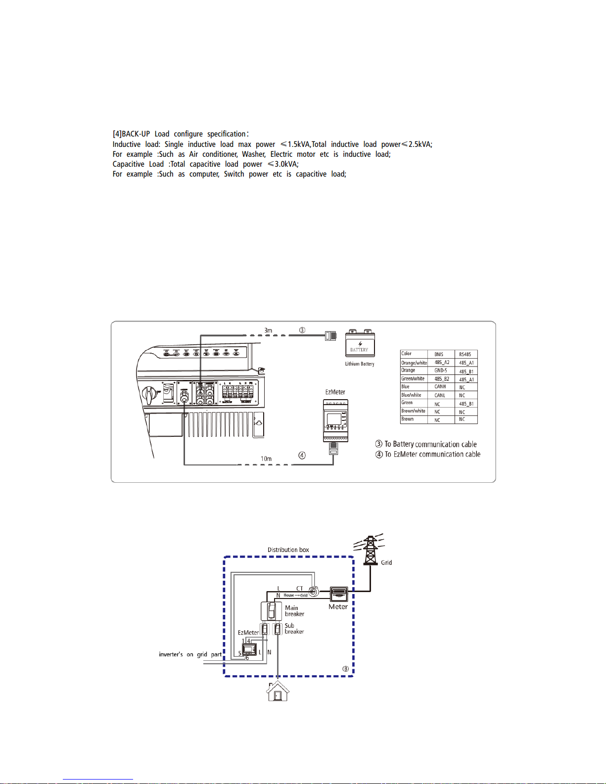
1.3 Data cable connection
5048D-ES needs to communicate with Ezmeter (in the package box) and the BYD battery for
normal operation. These communications are both through premade factory CAT5 cables.
To the meter
5048D-ES inverter offered together with an ezmeter which is for monitoring the load.
Attention point:
a. Part 1 on top of meter connects to power cable; part 4 on top of meter connects to neutral
cable for powering up the meter.
b. CT position is between the main switch and the customer power meter.
c. CT clamp has its direction:
There is clear label on CT to indicate the right orientation. On the label, HOUSE indicates house
side, GRID indicates GRID side.
To wrongly put the meter, the monitoring will have abnormal data. If the house load is unusual
high and equal to PV plus Grid, then this indicates the CT clamp connected reversely wrongly.
d. Check the CT tiny cable connected to the meter, the part 5 is white cable, part 6 is black
cable.
e. The premade factory cable to ezmeter on inverter can be unplugged and plug the new one if
the distance is not long enough.
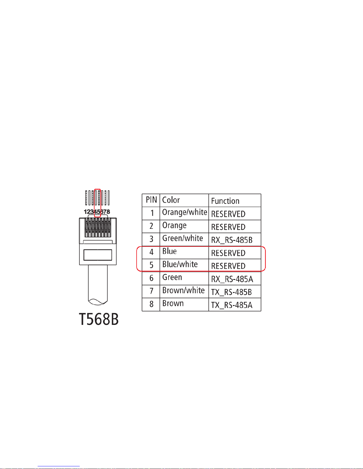
To the battery
Cut the crystal terminal off, remake the data cable to only have Blue on pin 4, Blue/White on pin
5.
Then refer to BYD manual for giving the battery address, set up physical cable between batteries.
 Loading...