

User's Manual
Introduction
Z-Wave Roller Shutter Controller is an ideal for the remotely electric
motor controller. It is used to control the motors of rollers, shades,
blinds, venetian blinds and similar sun shade, which are single phase
AC powered. The module can be controlled either through a Z-Wave
network or through the wall switch, and measures power
consumption of motor.
Z-Wave Roller Shutter needs to motor calibration before use, please
refer to CONFIGURATION command class parameter 0x01. Z-Wave
Roller Shutter’s positioning calibration does not apply to m otor
without obstacle detection, using this fu nction may cause
unpredictable problems, please make sure your motor has obstacle
detection function before positioning calibration.
Package Contents
■ Z-Wave Roller Shutter Controller x1
■ User Manual x1
Command Class
Device Information
GENERIC_TYPE_SWITCH_MULTILEVEL
SPECIFIC_TYPE_CLASS_C_MOTOR_CONTROL
z-wave protocol Command Class Node Info
COMMAND_CLASS_ZWAVEPLUS_INFO_V2
COMMAND_CLASS_VERSION_V3
COMMAND_CLASS_MANUFACTURER_SPECIFIC_V2
COMMAND_CLASS_DEVICE_RESET_LOCALLY_V1
COMMAND_CLASS_POWERLEVEL_V1
COMMAND_CLASS_SWITCH_MULTILEVEL_V3
COMMAND_CLASS_CONFIGURATION_V1
COMMAND_CLASS_ASSOCIATION_V2
COMMAND_CLASS_ASSOCIATION_GRP_INFO_V1
COMMAND_CLASS_SWITCH_BINARY_V1
COMMAND_CLASS_METER_V3
COMMAND_CLASS_FIRMWARE_UPDATE_MD_V4
COMMAND_CLASS_SUPERVISION_V1
COMMAND_CLASS_Transport_Service_V2
COMMAND_CLASS_SECURITY_V1
COMMAND_CLASS_SECURITY_2_V1
The Below listed Command Class are all supported the S
ecurity S2
COMMAND_CLASS_VERSION_V3
COMMAND_CLASS_MANUFACTURER_SPECIFIC_V2
COMMAND_CLASS_DEVICE_RESET_LOCALLY_V1
COMMAND_CLASS_POWERLEVEL_V1
COMMAND_CLASS_SWITCH_MULTILEVEL_V3
COMMAND_CLASS_CONFIGURATION_V1
COMMAND_CLASS_ASSOCIATION_V2
COMMAND_CLASS_ASSOCIATION_GRP_INFO_V1
COMMAND_CLASS_SWITCH_BINARY_V1
COMMAND_CLASS_METER_V3
COMMAND_CLASS_FIRMWARE_UPDATE_MD_V4
COMMAND_CLASS_SUPERVISION_V1
Detailed description of each command class
【ZWAVEPLUS INFO command class】
The Z-Wave Plus Info Get Command is used to get additional
information of the Z-Wave Plus device in question.
【VERSION command class】
The user can enquire the version of the unit using VERSION_GET
command. It will return VERSION_REPORT Command. Version
Report Command:
[Command Class Version, Version Report, Z-Wav e Library Type, ZWave Protocol Version, Z-Wave Protocol Sub Version, Application
Version, Application Sub Version]
【MANUFACTURER SPECIFIC command class】
The user can use the Manufacturer Specific Get Command to request
manufacturer specific information from another node.
Manufacturer Specific Report Command:
[Command Class Manufacturer Specific, Manufacturer ID 1,
Manufacturer ID 2, Product Type ID 1, Product Type ID 2, Product ID
1, Product ID 2]
【DEVICE RESET LOCALLY command class】
The Dev ice Res et Locally Command Class is used to notify central
controllers that a Z-Wave device is resetting its network specific
parameters.
【POWERLEVEL command class】
The Power level Command Class defines RF transmit power
controlling commands useful when installing or testing a network.
The commands make it possible for supporting controllers to set/get
the RF transmit power level of a node and test specific links between
nodes with a specific RF transmit power level.
【BASIC command class】
Control the roller shutter to be opened or closed after receiving the
BASIC_SET command.
To be opened:
[Command Class Multilevel, Multilevel Set, Value = 0xFF]
To be closed:
[Command Class Multilevel, Multilevel Set, Value= 0x00]
To be the percentage of full opened position:
[Command Class Multilevel, Multilevel Set, Value = 0x01~0x63]
【SWITCH MULTILEVEL command class】
Control the roller shutter to be opened, closed, stopped or be the
percentage of full opened position after receiving the SWITCH
MULTILEVEL command.
To be opened:
[Command Class Multilevel, Multilevel Set, Value = 0xFF]
To be closed:
[Command Class Multilevel, Multilevel Set, Value= 0x00]
To be the percentage of full opened position:
[Command Class Multilevel, Multilevel Set, Value = 0x01~0x63]
To be stopped:
[Command Class Multilevel,
SWITCH_MULTILEVEL_STOP_LEVEL_CHANGE]
【CONFIGURATION command class】
This class is used for setting certain vendor specific configuration
variables. See the following table for configuration variables:
Parameter
Name
Size
(byte)
Range
Default
value
Description
1
(0x01)
Positioni
ng
Calibratio
n
1
0 - 1 0 0: Disable
1: Executing
calibration
2
(0x02)
External
switch
Protectio
n
1
0 - 1 0 0: Enable external
switch
1: Disable external
switch
3
(0x03)
When
the door
is
opened,
set the
delay
time for
automati
c closing.
2
0 32767
0
0: Disable automatic
closing
1 - 32767: The door
will be closed
automatically in 1 32767sec
4
(0x04)
When
the door
is open,
set the
delay
time for
automati
c
notificati
on.
2
0 32767
0
0: Disable automatic
notification
1 - 32767: The
notification will be
sent automatically in
1 - 32767sec
5
(0x05)
Set the
operatio
n mode
1
0 - 1 0 0: Roller Shutter
1: Venetian
(up/down and slate
rotation)
6
(0x06)
Set the
angle of
blinds
1
0 - 6 0 Angles of blinds
0:0∘
1:30∘
2:60∘
3:90∘
4:120∘
5:150∘
6:180∘
7
(0x07)
Set the
slats
turning
time
1
0 - 127
15
(1.5sec
)
0:Disable.
1 - 127: 0.1 - 12.7 sec
8
(0x08)
Set the
delay
time to
start the
motor up
to the
blade
1
0 - 127 0 0:No offset time
1 - 127: 0.1 - 12.7 sec
9
(0x09)
Set the
delay
time to
start the
motor
down to
the blade
1
0 - 127 0 0:No offset time
1 - 127: 0.1 – 12.7 sec
10
Set the 1 0 - 100 0 0:Disabled
(0x0A)
power
changed
percenta
ge to
send the
power
report
1 - 100: 1% - 100%
11
(0x0B)
Set the
time
interval
of
reporting
watts in
seconds
2
0,
60 32767
300
sec
0:Disable
60 - 32767:
60 - 32767sec
12
(0x0C)
Set the
time
interval
of
reporting
KWH in
seconds
2
0,
60 32767
3600
0:Disable
60 - 32767:
60 - 32767sec
【ASSOCIATION command class】
The device can be set 1 auto-report ID in Group 1.
The device sends an unsolicited command to the configured
destinations when triggered by an event.
Group1:"Lifeline" :
【ASSOCIATION GRP INFO command class】
The purpose of the Association Group Information (AGI) Command
Class is to allow a device to report the capabilities of each
association group supported by the device.
【SWITCH_BINARY command class】
Control the roller shutter to be opened or closed after receiving the
SWITCH BINARY command.
To be opened:
[Command Class SWITCH_BINARY, Set Value = 0xFF]
To be closed:
[Command Class SWITCH_BINARY, Set Value = 0x00]
【METER command class】
The Meter Command C lass is intended for Z-Wave enabled devices
capable of reporting energy measurements in addition to any main
functionality or features e.g. an appliance module rep orting the
current consumption of the connected load. The Meter command
class not support V1&V2 version. And it will take about 3 seconds to
show the meter report on the request sending device.
【FIRMWARE UPDATE META DATA command class】
Support OTA (On-The-Air) firmware update function.
【COMMAND_CLASS_SECURITY_V1】
【COMMAND_CLASS_SECURITY_2_V1】
This device is a security enabled Z-Wave Plus product that is able to
use encrypted Z-Wave Plus messag es to communicate to other
security enabled Z-Wave Plus products.
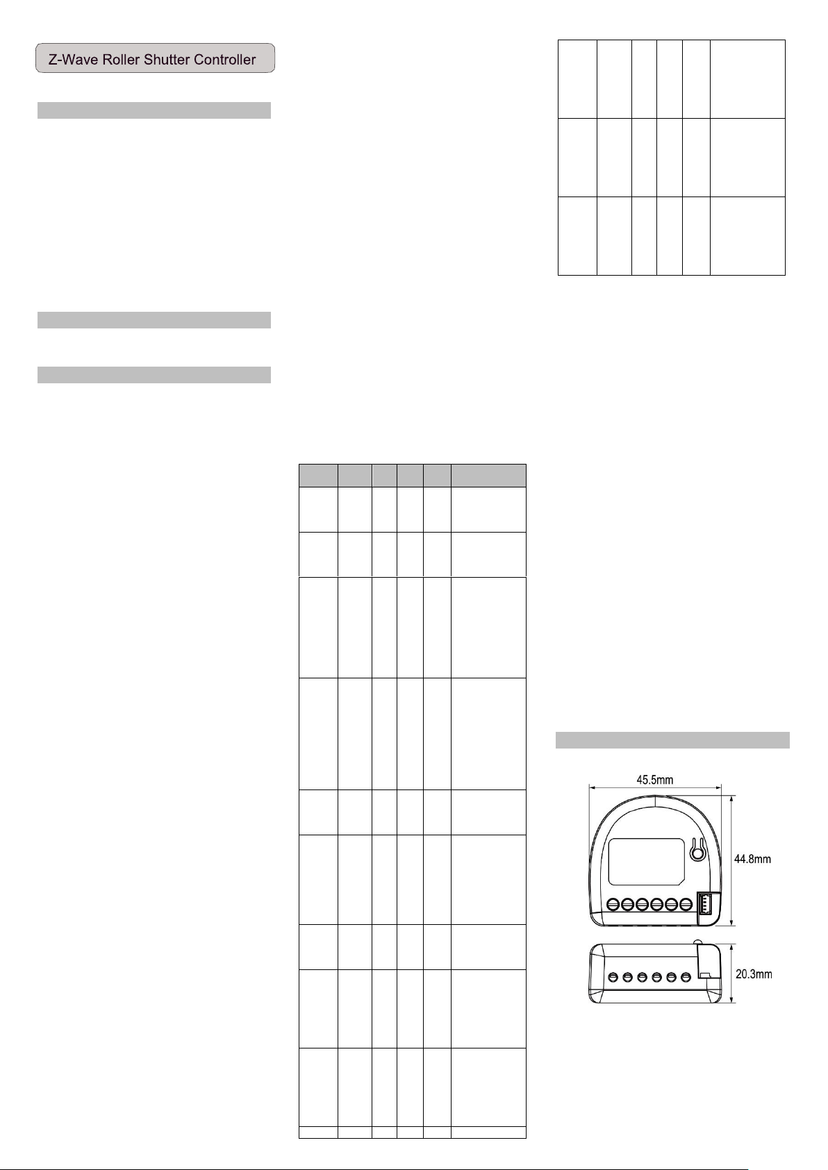
Product Overview
Product Dimensions
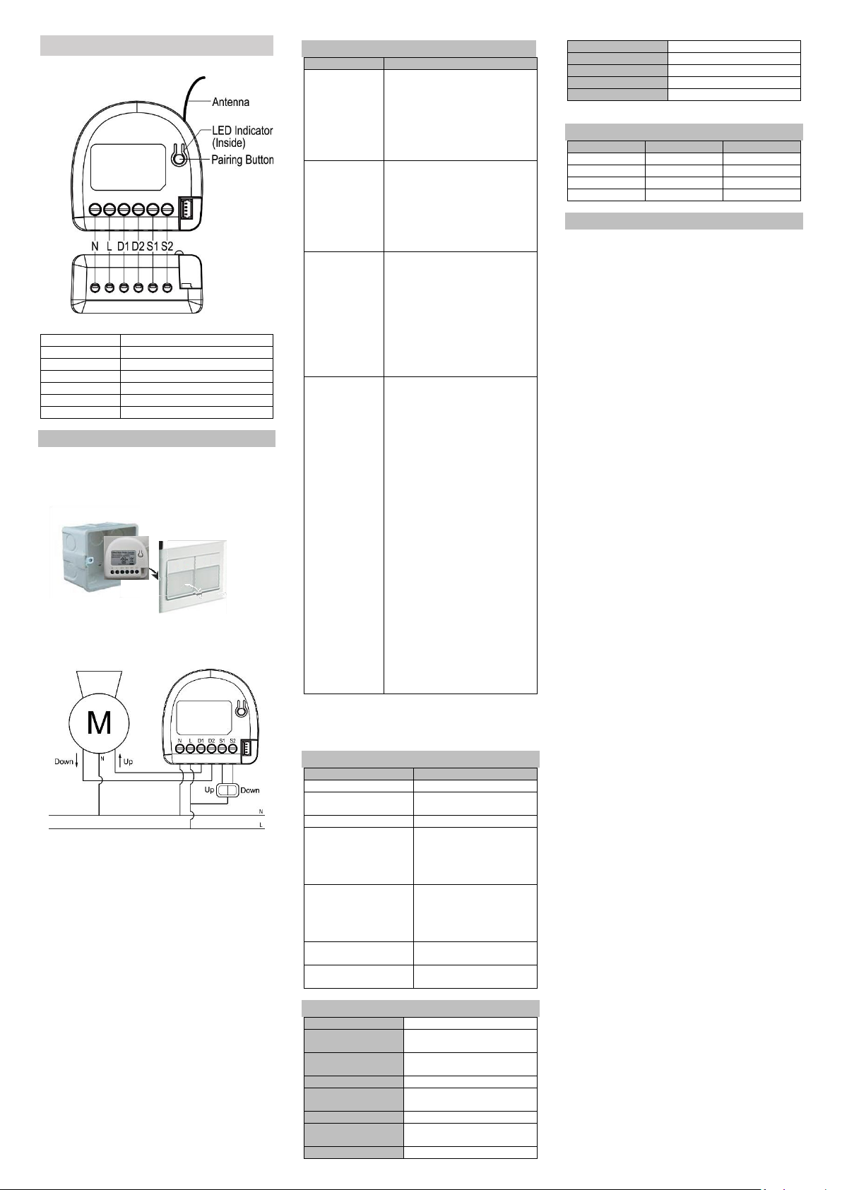
Application Diagram
Main Diagram
- Notes for the Diagram
N
Neutral lead
L
Live lead
D1
Output for motor UP
D2
Output for motor DOWN
S1
Input for switch/push button UP
S2
Input for switch/push button DOWN
Pairing Button
Include/ Exclude/ Reset Button
Device Installation
1. Before installation make sure the voltage supply is disconnected.
2. Put the device into a small box (such as wall box or small plastic
box and etc.) near the motor to avoid direct exposure danger in
the air and to the water.
3. Connect the motor of Roller Shutter and Switch in accordance
with the wiring diagram presented on Fig. 1 (roller blinds,
venetian blinds).
Figure 1. Roller Shutter wiring diagram
4. Locate the antenna far from metal elements (as far as possible)
5. Do not shorten the antenna.
6. Turn on the power supply keeping the necessary safety
precautions.
7. Include the module into the Z-Wave network, please refer to the
"Operation" section for “Inclusion” operating instructions.
8. Executing the positioning calibration process, please refer to the
"Operation" section for “Positioning calibration” operating
instructions.
CAUTION!
! Read this manual before attempting to install the device! Failure
to observe recommendations included in this manual may be
dangerous or cause a violation of the law. The manufacturer will
not be held responsible for any loss or damage resulting from not
following the instructions of operating manual.
! Any maintenance work on controlled devices may be performed
only after the power supply has been disconnected.
! Do not connect the module to loads exceeding recommended
values. Connect the module only in accordance with the diagram
presented in the manual. Improper connections may be
dangerous.
Operation
Function
Operation
Add for Inclusion
1. Put the Z-Wave Controller into
inclusion mode, and press the pairing
button 3 times in 2 seconds to include
the module.
2. Put the Z-Wave Controller into
inclusion mode, and press the “external
swtich1” or “external swtich2” 3 times
in 2 seconds to include the module.
Remove for
Exclusion
1. Put the Z-Wave Controller into
exclusion mode, and press the pairing
button 3 times in 2 seconds to exclude
the device.
2. Put the Z-Wave Controller into
inclusion mode, and press the “external
swtich1” or “external swtich2” 3 times
in 2 seconds to include the module.
Reset
1. Press the pairing button 3 times in 2
seconds and press and hold the pairing
button for more than 5 seconds at the
3rd time.
2. The module is excluded and restores to
factory default setting.
3. Then the module will be in auto-
inclusion mode for 2 minutes.
Please use this procedure only when the
network primary controller is missing or
otherwise inoperable.
Positioning
calibration
Positioning calibration is a process during
which a Roller Shutter learns the position
of the limit switches and a motor
characteristic. Calibration is mandatory in
order for the Roller Shutter to correctly
recognize a roller blind position. The
procedure consists of an automatic, full
movement between the limit switches
(up, down, and up again).
There are three kinds of positioning
calibration operation as follows:
1. Parameter Setting: Parameter 1(0x01),
Size 1(byte), Value 1.
2. Pairing Button: Press and hold the
button for 6 to 10 seconds, release the
button (less than 2 seconds), and then
click the button (less than 2 seconds)
3. External Switch: Use the same external
switch (S1 or S2), turn on and off 3
times. Turn ON =>OFF => ON=> OFF=>
ON=> OFF (Turn ON: lasts 3 to10
seconds), Turn OFF: less than 2
seconds)
Note: If an emergency is encountered
during the positioning calibration process,
please click the external switch, the
pairing button, or the APP to abort the
positioning calibration processes.
Notice: Including a node ID allocated by Z-WaveTM Controller
means “Add” or “Inclusion”. Excluding a node ID allocated by Z WaveTM Controller means “Remove” or “Exclusion”.
LED Indicator
LED Signal
Status
LED OFF
Power OFF
Red & Green blinking by
turns
Power ON (No node ID)
Solid Green
Power ON (Included)
Green blinking twice per
second for 3 seconds
(1) Inclusion process success
(2) Exclusion process success
(3) Parameter setting success
(4) Positioning calibration
success
Red blinking twice per
second for 3 seconds
(1) Inclusion process failed
(2) Exclusion process failed
(3) Parameter setting failed
(4) Positioning calibration
failed
Green blinking twice per
second for 2 minutes
Auto Inclusion Mode
Red blinking twice per
second
Overload Protection
Specification
Wireless Type
Z-Wave Plus
Frequency
EU: 868.4 MHz
US: 916.0 MHz
Operating Distance
up to 100m outdoors ;
up to 30m indoors
Power Supply
110 -230 VAC ±10% 50 / 60 Hz
Rated load current of AC
output (resistive load)
2 @ 5A (230 VAC)
Rated power of Motor
Motor under 170W
Power measurement
accuracy
P = 0-40 W, ± 2 W; P > 40 W, ±3%
Electricity Consumption
<0.5W
LED
Red /Green LED*1
Switching
Relay x 2
Data Rate
100 kbps
Operation temperature
-10°C ~ 40°C
Dimensions (L x W x H)
45.5 x 44.8 x 20.3 mm
*Specification is subject to change without prior notice.
External Switch Operation
S1
S2
Motor Action
Turn OFF
Turn OFF
STOP
Turn ON
Turn OFF
UP
Turn OFF
Turn ON
DOWN
Turn ON
Turn ON
STOP
Regulatory Compliance
CE Caution
Electromagnetic compatibility and Radio spectrum Matters (ERM);
Short Range Devices (SRD); Radio equipment to be used in the 25
MHz to 1,000 MHz frequency range with power levels ranging up to
500 mW; Part 2: Harmon ized EN covering essential requirements
under article 3.2 of the R&TTE Directive.
FCC Caution
This device complies with Part 15 of the FCC rules standard.
Operation is subject to the following two conditions:
1. This device may not cause harmful interference, and
2. This device must accept any interference received, including
interference that may cause undesired operation.
Any changes or modifications not expressly approved by the party
responsible for compliance could void the authority to operate
equipment. This device and its antenna must not be co-located or
operating in conjunction with any other antenna or transmitter. This
equipment complies with FCC radiation exposure limits set forth for
an uncontrolled environment. This equipment should be installed
and operated with minimum distance 20cm between the radiator &
your body. This equipment has been tested and found to comply
with the limits for a Class B digital device, pursuant to part 15 of the
FCC Rules. These limits are designed to provide reasonable
protection against harmful interference in a residential installation.
This equipment generates, uses and can radiate radio frequency
energy and, if not installed and used i n acc ordance with the
instructions, may cause harmful interference to radio
communications. However, there is no guarantee that interference
will not occur in a particular installation. If this equipment does
cause harmful interference to radio or television reception, which
can be determined by turning the equipment off and on, the user is
encouraged to try to correct the interference by one or more of the
following measures:
- Reorient or relocate the receiving antenna.
- Increase the separation between the equipment and receiver.
- Connect the equipment into an outlet on a circuit different
from that to which the receiver is connected.
- Consult the dealer or an experienced radio/TV technician for
help.
WEEE Information
For EU (European Union) member users: According to the WEEE
(Waste electrical and electronic equipment) Directive, do not
dispose of this product as household waste or commercial waste.
Waste electrical and electronic equipment should be appropriately
collected and recycled as required by practices established for your
country.
For information on recycling of this product, please contact your
local authorities, your household waste disposal service or the shop
where you purchased the product.
Z-Wave Plus
This product can be included and operated in any Z-Wave network
with other Z-Wave certified devices from other manufacturers
and/or other applications. All non-battery operated nodes within
the network will act as repeaters regardless of vendor to increase
reliability of the network.
This device must be used in conjunction with a Security Enabled ZWave Controller in order to fully utilize all implemented functions.
Security S2
Security S2 is supported with the Au thenticated and
UnAuthenticated levels of security. The Authenticated level requires
the user to enter the PIN code or QR code printed on the box of the
Roller Shutter. The UnAuthenticated level does not require the PIN
code. Both security levels will encrypt nearly all communication
using AES-128 encryption to ensure reliable and secure
communication.
SmartStart
Sigma Designs technology makes installation easy and secure. Simply
install Roller Shutter into a wall and it will autom atically attempt to
join the Z-Wave network. During the inclusion process, your home
automation system will ask for a PIN code or to scan a QR code. The
pin code is printed on the back of Roller Shutter along with the QR
code. Simply enter the PIN code or scan the QR code with a
compatible device. Each QR code is unique for every device.
SmartStart uses the latest Security S2 encryption technology for all
radio communication. It is completely backwa rds compatible with
non-SmartStart systems if your home automation system doesn’t

support it yet.
Ex:
WARNING: Important safety instructions.
It is important for the safety of persons to follow these instructions.
Save these instructions.
- Important safety instructions. Follow all instructions, since
incorrect installation can lead to severe injury
- All wiring interconnecting with this controller is non-isolated
hazardous live parts.
- The appliance is not to be used by persons (including children)
with reduced physical, sensory or mental capabilities, or lack
of experience and knowledge, unless they have been given
supervision or instruction.
- Frequently examine the installation for imbalance and signs of
wear or damage to cables and springs.
- Do not use if repair or adjustment is necessary.
- Do not allow children to play with fixed controls. Keep remote
controls away from children.
- The drive shall be disconnected from its p ower source during
cleaning, maintenance and when replacing parts.
- Indoor use only.
- Never install independent switch for each S1 and S2, to
prevent the activation on D1 and D2 at the same time.
- Material used only for the 16 AWG copper wires and the
suggested strip length is 4.5 ~ 5 mm.
- Equipment shall not be interconnected with the output of
another power source.
- High Voltage - Disconnect power supply before servicing.
- Risk of Electric Shock - More than one disconnect switch may
be required to de-energize the device before servicing.
 Loading...