

Page 1
Z-Wave Home Gateway
™
FG3200 ( Z-Wave
®
Home gateway )
Page 2

Index
INDEX ................................................................... 0
INTRODUCE ......................................................... 1
PRODUCT DESCRIPTION AND SPECIFICATION ..... 2
PACKAGE CONTENTS ........................................... 3
ICON AND COMMAND CLASSES .......................... 3
CONNECTION: ...................................................... 7
1. ANDROID APP DOWNLOAD ............................... 7
2. ADD GATEWAY ................................................ 8
3. DASHBOARD ................................................... 9
4. EDIT ............................................................ 10
5. SETTING PAGES .............................................. 11
5.1 GATEWAY MANAGEMENT .............................. 12
5.1.1 ADD(INCLUSION) ..................................... 13
5.1.2 REMOVE(EXCLUSION) ................................ 14
5.1.3 LEARN MODE ........................................... 15
5.1.4 RESET ..................................................... 17
5.1.5 FACTORY RESET: ....................................... 17
6. DEVICE PAGE ................................................. 19
7. ADD IP CAMERA ........................................... 22
8. AUTOMATOR: SETTING SCENARIOS .................... 27
Page 3

1
Introduce
This gateway is a Z-Wave® enabled controller and security
enabled Z-Wave plus product. Z-Wave® enabled devices
displaying the Z-Wave® logo can also be used with it
regardless of the manufacturer, and ours can also be used in
other manufacture’s Z-Wave® enabled networks.
All non-battery operated nodes within the network will act as
repeaters regardless of vendor to increase reliability of the
network.
Our Z-Wave® Home Gateway is designed to connect and
communicate multi Z-Wave devices. Feature packed, tiny and
powerful Z-Wave® home gateway to communicate. Monitor
and control your home remotely from anywhere in the world
using a mobile phone or tablet PC. Enhanced expansion
capability plus stylish appearance, the Home Gateway series
are the most versatile accessories to the Z-Wave® users.
Page 4
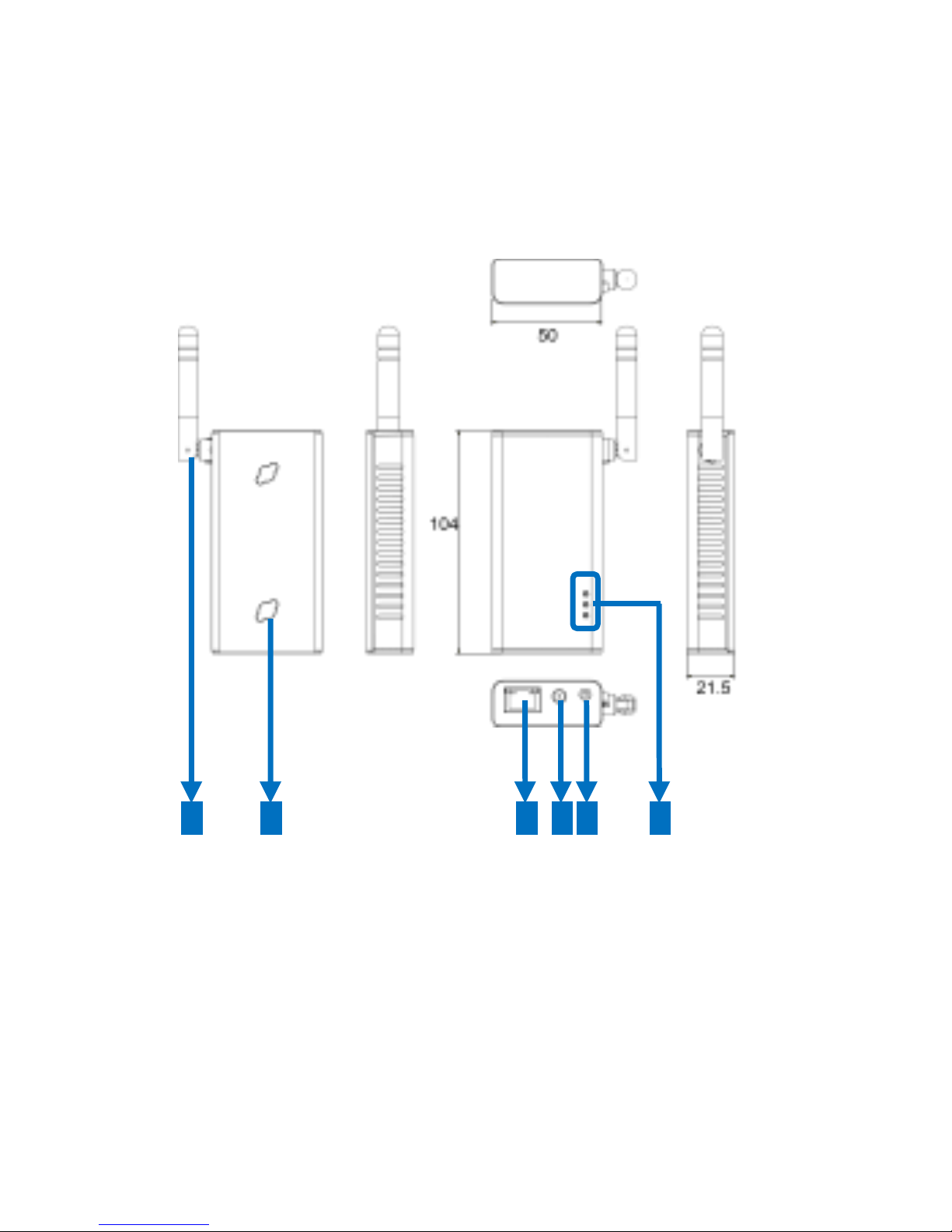
2
Product Description and
Specification
5 4 3 2 6
1
Page 5
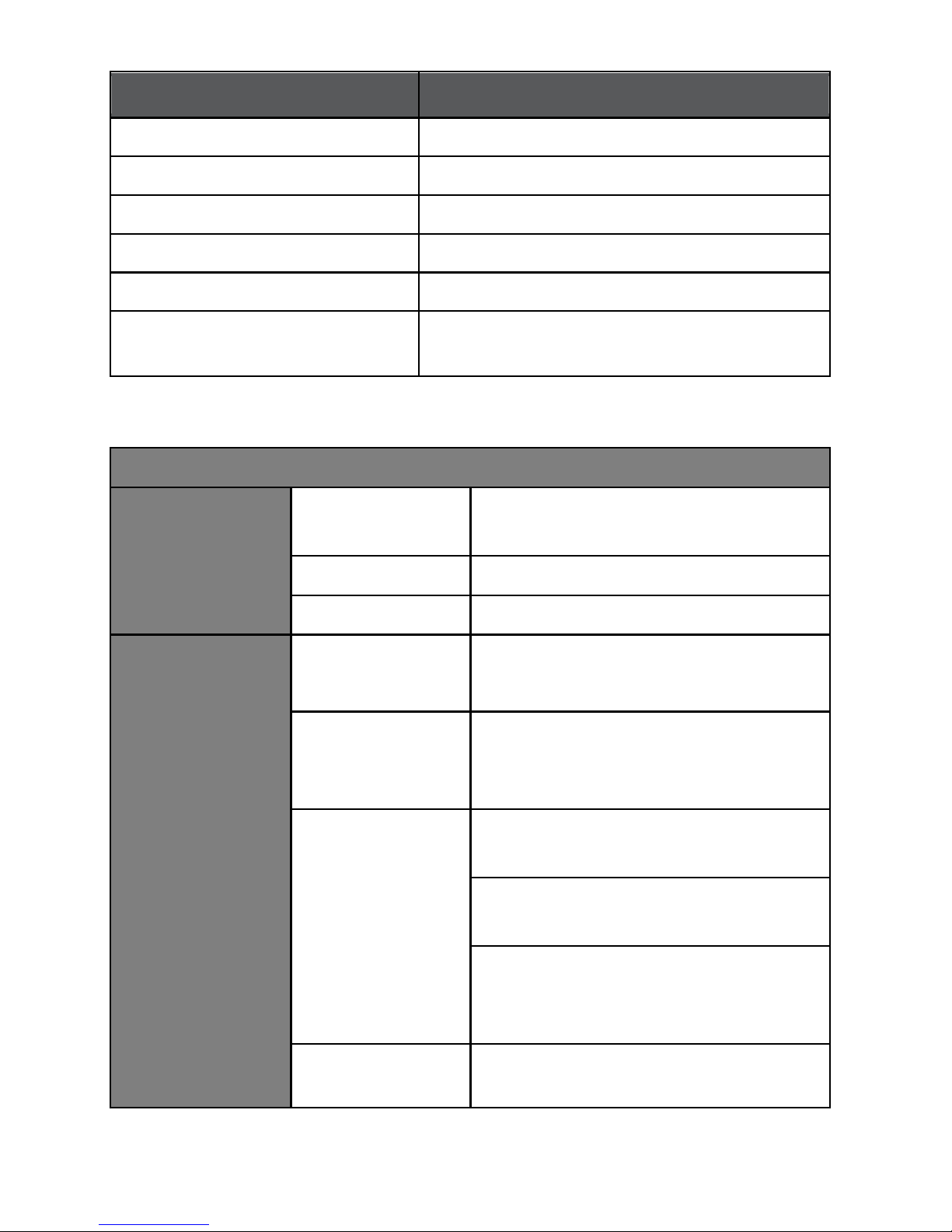
Item
Description
1 Antenna
2.4GHz Wi-Fi
2 Wall Mount Hole
Mounts the device to the wall
3 RJ45 port
Connects to an Ethernet
4 DC-in jack
Connects to the power adapter
5 Reset
Restores to the default settings
6 LED
Power (Red); LAN / WAN (Green);
Z-Wave® (Blue)
Specification
Core
CPU Clock
Rate
400MHz
DDR2 SDRAM
64M Bytes
Flash
8M Bytes
Wireless
Wi-Fi
Standard
IEEE 802.11 b/g/n Wireless
Local Area Networks
Wi-Fi
Frequency
Range
2.4G~2.5GHz
Measured
Data Rates
1 Mbps, 2 Mbps, 5.5 Mbps, 11
Mbps in 802.11b Modes
6Mbps, 36Mbps, 48Mbps,
54Mbps in 802.11g Modes
MCS0~MCS7 in both HT20 and
HT40 in 802.11n Modes (up to
150Mbps)
Measured
2.412, 2.442, 2472GHz in
802.11 b/g and 802.11n HT20
Page 6
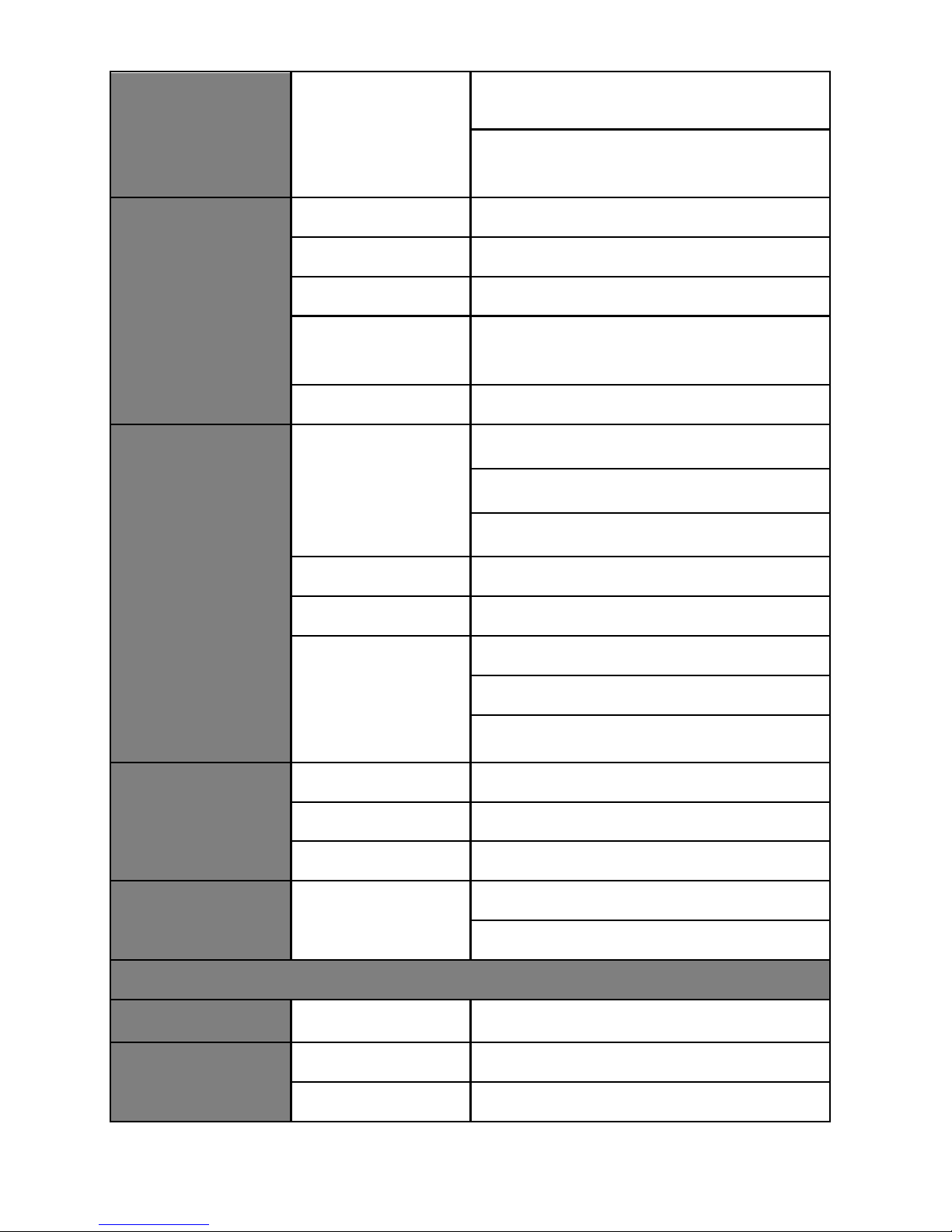
Channels
modes
2.422, 2.437, 2.452, in 802.11n
HT40 mode
Ethernet
Interface
RJ-45
Standard
IEEE 802.3
Speed
10/100Mbps
LAN
For Bridge or Wireless ISP
Mode
WAN
For Gateway Mode
Z-Wave®
RF Frequency
908.42 MHz (US)
868.42 MHz(EU)
922.5 MHz (JP)
Data Rate
9.6 / 40 / 100 kbit/s
Output Power
-21…+2.5 dBm
High
Sensitivity
(Typical
Values)
-99 dBm @9.6 kbit/s
-97 dBm @40 kbit/s
-93 dBm @100 kbit/s
LED Indicator
Display
Red
Power
Green
LAN / WAN
Blue
Z-Wave®
Micro SD Slot
(Option)
TF Card
Support up to ver. 2.0 (SDHC)
Compatible with ver. 3.0 (SDXC)
Power
DC Jack
Input
5VDC
Power
Adapter
Input
AC 100-240V
Output
DC 5V/2.5A
Page 7

Power
Consumption
Normal Mode
1.70W
Housing
Physical
Properties
Material
ABS (Plastic)
Dimension
104(L) x 50(W) x 17.5(H) mm
Weight
64.5g
Working
Environment
Operation
Temperature
0~60 degree
Storage
Temperature
-20~85 degree
Relative
Humidity
5~90% (Non-condensing)
Compliance
CE, FCC
Package Contents
Z-Gate
TM
Built-in Antenna
5V/2.5A Adapter
Page 8
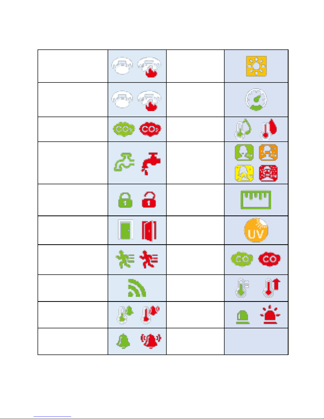
Icon and Command Classes
Heat(Sensor)
Luminance
Smoke
Power
CO2
Humidity
Water
PM25
Tamper
Distance
Door Window
Ultraviolet
Motion
CO
General
Alarm Heat
Air temperature
Siren
Non Support
Notification
Page 9

Gateway Z-Wave Support Command Classes
COMMAND_CLASS_ZWAVEPLUS_INFO V2
COMMAND_CLASS_VERSION V2
COMMAND_CLASS_MANUFACTURER_SPECIFIC V1
COMMAND_CLASS_DEVICE_RESET_LOCALLY V1
COMMAND_CLASS_ASSOCIATION V2
COMMAND_CLASS_ASSOCIATION_GROUP_INFORMATION V1
COMMAND_CLASS_APPLICATION_STATUS V1
COMMAND_CLASS_CRC_16_ENCAP V1
COMMAND_CLASS_POWERLEVEL V1
COMMAND_CLASS_SECURITY V1
Gateway Z-Wave Controlled Command Classes:
COMMAND_CLASS_ZWAVEPLUS_INFO V2
COMMAND_CLASS_ASSOCIATION V2
COMMAND_CLASS_ASSOCIATION_GROUP_INFORMATION V1
COMMAND_CLASS_BASIC V1
COMMAND_CLASS_BATTERY V1
COMMAND_CLASS_SWITCH_BINARY V1
COMMAND_CLASS_SENSOR_BINARY V2
COMMAND_CLASS_CONFIGURATION V1
COMMAND_CLASS_CRC_16_ENCAP V1
COMMAND_CLASS_MANUFACTURER_SPECIFIC V1
COMMAND_CLASS_METER V4
COMMAND_CLASS_MULTI_CHANNEL V4
COMMAND_CLASS_MULTI_CHANNEL_ASSOCIATION V3
COMMAND_CLASS_SENSOR_MULTILEVEL V5
COMMAND_CLASS_SWITCH_MULTILEVEL V1
COMMAND_CLASS_NOTIFICATION V4
COMMAND_CLASS_NO_OPERATION V1
COMMAND_CLASS_SECURITY V1
Page 10

COMMAND_CLASS_VERSION V2
COMMAND_CLASS_WAKE_UP V2
If FG3200 controller receives a Basic command, it will ignore the
command.
Z- Wave’s Groups (Association Command Class Version 2)
The gateway will send DEVICE_RESET_LOCALLY_NOTIFICATION to
associated Z-Wave devices when it is reset or factory-reset.
It supports 1 association group which supports only one (maximum)
associated node.
Group 1 support command DEVICE_RESET_LOCALLY_NOTIFICATION of
COMMAND_CLASS_DEVICE_RESET_LOCALLY.
This only group supports
Page 11
Connection:
1. Android APP Download
1. Turn on any QR code APP on your mobile phone to scan QR
code below to automatically download and install the
application.
For Android
2. The APP is called “Z-Butler”. When the application is
activated, it will automatically search Z-Wave Home
Gateway IP address. The login account is admin, and the
password is 1234. The user can modify the account and
password in the settings section after logged in.
NOTE:
Before using APP, please activate the Wi-Fi function of mobile
device. The device should be able to locate the network
FG3200, please input the default password 89191200, and
make sure it is successfully connected.
Page 12

2. Add Gateway
1. Start Z-Butler app. Follow the instruction to Add New
Gateway. You can search gateway signal.
2. Click the pop-up gateway information bar.
3. Setup name, account and password. Account and
password default as “admin”/ “1234”.
Page 13

3. Dashboard
Enter Home page when Gateway is connected, Home page
shows Dashboard, Device, Setting Scenarios, IP Camera,
Settings, total 4 sections.
Page 14

4. Edit
On Homepage, top center shows connected Gateway, click
top right corner Refresh/Add Gateway.
Page 15

5. Setting pages
Including “Notification Settings”, ”Version Update”.
Page 16

5.1 Gateway Management
Including “Edit Gateway”, ”Remove Gateway”, ”Inclusion”,
”Exclusion”, ”Reset”, ”Set learn Start”, ”Set learn Stop”.
Page 17

5.1.1 ADD(Inclusion)
Ensure Gateway is connected, enter device page and click
“Inclusion” to include devices. After the inclusion show
window is finished, you can view the device at the device
interface.
Page 18

5.1.2 Remove(Exclusion)
Ensure Gateway is connected, enter device page and click
“Exclusion” to exclude devices. After the exclusion show
window is finished, you can view the device is remove from
the device interface.
Page 19

5.1.3 Learn Mode
Ensure the Gateway not include any device or Reset the
Gateway. You can review and control the device for learned
Gateway. Into the Learn Mode, show “Processing…”, operate
another Controller into add device mode, after the
completion of the study to be prompted to add success.
When you need initiate a replication of network information
from the controller to another controller or want to receive
network information, please enter "include" and "learn
mode".
Page 20

Page 21

5.1.4 Reset
Click “Reset”, show “Are you sure to reset Z-Dongle?”and
click OK to reset the Z-Wave network.
5.1.5 Factory Reset:
FG3200 Reset button 10 seconds after the reset to reset the
factory default
Reset
Page 22

* If this controller is the primary controller for your network,
resetting it will result in the nodes in your network being
orphaned and it will be necessary after the reset to exclude
and re-include all of the nodes in the network. If this
controller is being used as a secondary controller in the
network, use this procedure to reset this controller only in
the event that the network primary controller is missing or
otherwise inoperable.
Page 23

6. Device page
Will show the trigger device and related device icon on the
device page. You can also get the information of property for
each device from this page.
You can click the node number “>” to show the device node
settings:
“Advanced settings”, ”Remove Failed Node”, ”Node
Neighbor Update”, ”Replace Failed Node”
as attached photo.
Page 24

Click the Basic icon will get the current state of the Device.
Press Node number bar then select advanced stings and will
show the Configurations and Association
Page 25

6.1 The Network Rediscovery
Page 26

7. ADD IP Camera
First, please download the APP MyCamPro, and ensure
Gateway is connected.
1. Execute MyCamPro and click the “skip”.
2. Click the “+” .
3. Click the “Add manually”.
4. Click the “Wireless”.
5. Please input the default password 89191200 for
FG3200R1 and click the next step.
6. Select the connected IPCAM(ex:
IPCAM-XX-XXX)
7. Click the “+”.
8. Enter the default password and click “Add”.
9. Click the “live view”.
Page 27

Page 28

Page 29

1. Execute the Z-Butler APP.
2. Input the default account/password(admin/1234).
3. Enter the webcam page and click “+”.
4. Click the icon “magnifier”.
5. Click to join the IPCAM which you want.
6. Input the default username/password(admin/admin) and
click “Add”.
7. If success, you can view the IPCAM item in the webcam
page and then click this item you can see the live view.
Page 30

Page 31

8. Automator: Setting Scenarios
1. Select Scene settings from function bar.
2. Give the name to the scene task.
3. Click Select Sensor from Start Condition.
4. Select Door Sensor from Sensor Device.
5. Select On from Sensor Status. Click New Perform Action
to implement.
6. Click Select ZWave device from Perform Actions.
7. Choose Siren from Action Device. Select On from Sensor
Status.
8. Press OK.
9. Please Click “+” if you want to add more scene setting.
Page 32

10. Give a name to the new scene.
11. Click Select Sensor from Start Condition.
12. Choose Door Sensor from Sensor Device. Click OFF from
Sensor Status. Click New Perform Action.
13. Click Select ZWave Device from Perform Actions.
14. Select Siren from Action Device. Click OFF from Sensor
Status. Press OK.
15. Press OK.
16. You will see all the scene setting that you have made
from the list.
Page 33

Page 34

Page 35

Page 36

 Loading...