

HOT WATER
PRESSURE WASHERS
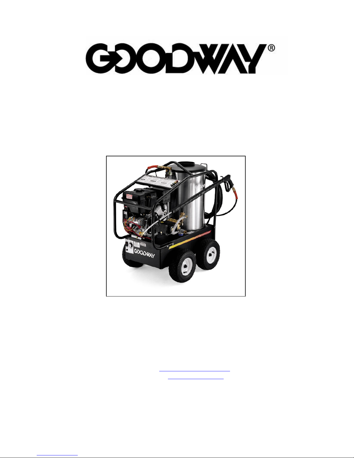
HPW-2600G and HPW-3500G
OPERATING AND MAINTENANCE INSTRUCTIONS
Goodway Technologies Corporation
420 West Avenue
Stamford, CT 06902
203-359-4708
Sales: 800-333-7467
Customer Service: 800-370-2855
Fax: 800-359-9625
E-mail:
Goodway is a ® trademark of Per K. Reichborn
Goodway reserves the right to improve products. Contact factory for the latest configuration and uses.
goodway@goodway.com
Internet: www.goodway.com
01/05

IMPORTANT SAFETY INSTRUCTIONS
1. Read all safety and operating instructions before using unit.
2. Read warnings on additive containers.
3. Ventilate work area when using toxic or pungent additives to reduce your exposure to toxic fumes.
4. Use protective wear, especially for the eyes and skin.
5. Be careful of slippery floors. Some additives make a normally safe area extremely slippery and
dangerous.
6. Keep children away from the machine and wash area.
7. Do not change nozzle size. Each machine is designed to operate with a specific size nozzle. An incorrect
nozzle could cause excessive pressure resulting in pump damage and possi ble personal injury. Refer to
parts list for correct nozzle size.
8. Do not point the nozzle where damage or injury could result. (e.g. Eyes, skin, etc). The water discharge
from this unit is under extremely high pressure.
9. Do not point the nozzle toward an electrical outlet as you risk severe shock and personal injury.
10. Use only recommended No. 1 or No. 2 fuel oil in this unit. Do not use gasoline, crankcase draining, or
oil containing gasoline or solvents.
11. Never run the unit in an enclosed area. Exhaust fumes are poisonous.
12. Whenever you stop spraying, always engage the safety latch on the trigger gun.
13. When changing nozzles, always turn the engine off and always relieve the pressure by triggering the gun.
Always engage the safety latch on the trigger gun. Always change the nozzle with the gun and wand
pointed away from you, and never pointed at any person or animal.
14. Keep flammable items (fuel, matches, etc.) away from engine while running or when it is hot.
15. DO NOT smoke when handling fuel.
16. Refuel only when the engine is cool.
17. DO NOT ABUSE the high pressure hose by driving over it. The hose may rupture and cause injury.
WARNING
RISK OF INJECTION OR SEVERE INJURY.
KEEP CLEAR OF NOZZLE. DO NOT DIRECT DISCHARGE STREAM AT PERSONS.
THIS EQUIPMENT IS TO BE USED ONLY BY TRAINED OPERATORS.
SAVE THESE INSTRUCTIONS
2

PRE-OPERATING INSTRUCTIONS
When unpacking the unit, if you find damage due to shipping, contact Goodway Technologies immediately.
INCOMING WATER SUPPLY
Connect a garden hose to the water inlet of the unit. The water supply must be able to deliver 8 gallons per
minute at a minimum pressure of 5 psi.
OUTGOING (HIGH PRESSURE) WATER
To the water outlet fitting, connect the high pressure hose, trigger gun, extension and a nozzle.
PUMP – OIL
Before operating the pump, check to see that the oil is level with the dot on the sight gauge which is located at
the rear of the pump. The oil level can also be checked using the dipstick which is attached to the oil filler cap.
Ensure that the vent hole in the cap/dipstick is clear of dirt. When oil is required, use #20 or #30 non-d etergent
heavy duty oil.
BURNER – FUEL
FILL THE BURNER FUEL TANK WITH #1 OR #2 DIESEL FUEL ONLY
WARNING
DO NOT USE GASOLINE, CRANKCASE OIL, ANY OIL CONTAINING GASOLINE,
OR ANY OTHER VOLATILE SUBSTANCE FOR THE BURNER.
BATTERY
A battery is not supplied with the unit. Install a 12 volt lead acid battery size 16 (e.g. Champion model no.
16B).
CAUTION:
BATTERY MUST BE INSTALLED BEFORE STARTING THE ENGINE.
(THE ENGINE WILL START WITHOUT THE BATTERY INSTALLED, BUT DAMAGE
WILL OCCUR)
3

OPERATING INSTRUCTIONS
STARTING THE PRESSURE WASHER
Make sure that the burner switch is “OFF”
Connect water supply to the Washer. Turn on the water. Pull the trigger to allow water to run through the unit
expelling all air.
CAUTION
NEVER RUN THE WASHER WITHOUT WATER TURNED ON.
PUMP DAMAGE WILL OCCUR.
STARTING THE ENGINE
Ensure the engine tank is full of gasoline.
Hold securely and open the Trigger gun to reduce the load on the engine
CAUTION
THE FORCE OF THE WATER LEAVING THE NOZZLE CAUSES
A “KICK-BACK” OR RECOIL AT THE TRIGGER GUN.
Turn the Engine Switch on.
Adjust the choke if necessary
Pull the rope to start engine
Advance the throttle to bring the engine to full speed. Turn off choke
BURNER START UP
Turn Burner Switch to “ON”
The burner will start. Adjust the thermostat to obtain desired water temperature.
(SEE NEXT PAGE FOR DETAILED BURNER START UP INSTRUCTIONS)
CAUTION
DO NOT RUN THE FUEL PUMP DRY. ALWAYS CHECK THE FUEL LEVEL IN THE
TANK BEFORE RUNNING THE WASHER
CHANGING PRESSURE
The variable Unloader Valve is already set to full pressure. Do not adjust the Unloader past the maximum
pressure, as this will not increase the performance, and the excessive shut-off pressure will damage the
Washer.
CLEANING CHEMICALS
These pressure washers have a chemical injector. To use, put a liquid cleaner (such as APC-100 available
form Goodway) into the supplied soap container. Drop the pick-up hose with strainer into the container.
Replace the quick connect nozzle with the black low pressure nozzle. Soap will now be drawn into the water.
To stop chemical injection replace the low pressure nozzle with one of the three high pressu re nozzles.
STOPPING THE WASHER
Turn off Burner Switch.
Pump cold water through the Washer for two minutes to flush out any remaining chemical (if used) and to cool
down all components.
Slow the engine to an idle and turn off the engine
4

BURNER START UP INSTRUCTIONS
Note: The following steps are only required when installing a new burner.
1. Set the Thermostat substantially above water temperature of the incoming water supply.
(In temperate regions, this is around 50 degrees Fahrenheit.)
2. Turn on the burner switch.
3. As soon as the burner motor starts rotating, bleed (prime) the fuel pump. To do this, attach the clear
plastic hose over the vent plug. Loosen the plug and catch the fuel in an empty container. Tighten the
plug when all the air appears to be eliminated.
4. If the burner stops during bleeding, wait three to five minutes for the control Safety Switch to cool, then
reset it manually.
5. If the burner stops after flame is established, additional venting is probably required. Repeat the bleeding
procedure.
CAUTION
Do not attempt to start the burner when excess fuel has accumulated, or
when the furnace or boiler is full of vapor, or when the combustion
chamber is hot.
ADJUSTING THE BURNER
NOTE: The settings below have already been completed for the unit, so the follo wing
instructions for adjusting, apply only if a new burner or coil is installed.
1. Allow sufficient air to obtain a clean looking flame by loosening the lock screws and moving the air shutter,
and if necessary, the bulk air band.
2. Draft Control Adjustments: The unit is set up in the factory to burn cleanly into
atmospheric conditions. Therefore, if a chimney is fitted to the machine, an “O” draft would be the optimum
condition.
3. Final Air-Adjustments: Allow at least ten minutes for warm-up, and longer if the
unit is new, in order to burn off the oil deposits on the heat exchanger and other surfaces. Check and adjust all
controls. (See Manufacturer’s Instruction sheets.) Test the primary control Safety Switch to insure a safety
shutdown will occur in the event of equipment malfunction.
5

SAFETY COMPONENTS
UNLOADER VALVE
The Unloader Valve allows all of the water delivered by the pump to return to the pump suction side. If the
trigger gun is closed or “OFF”, the Unloader Valve goes into the “bypass mode” and the pump runs without
pressure. HOWEVER, THE PUMP MAY BE SEVERELY DAMAGED, DUE TO EXCESSIVE
OVERHEATING, IF LEFT RUNNING IN THE “BYPASS MODE” OR “GUN-OFF” SITUATION FOR MORE
THAN 6 MINUTES.
SAFETY RELIEF VALVE
The Relief Valve prevents the machine from being subjected to abnormally high pressures. If this situation
occurs, the valve will blow off relieving the pressure in the coil. This valve may also operate if the Unloader is
adjusted too high.
PRESSURE SWITCH
The Pressure Switch ensures that there is pressure, and therefore there is water flow at the he ad of the pump.
This control does not operate at less than 300 psi. Therefore if the pump is on “bypass mode”, the burner will
not operate.
THERMOSTAT
The built-in thermostat stops the unit from overheating. Maximum temperature of the unit is 300° F (150°C)
Above this temperature, the burner stops automatically.
THINGS TO CHECK REGULARLY
1. Check for SYSTEMS LEAKS. Leaks in the pressure side of the system can cause premature wear (or
even failure) of the pump. The WARNING signal for this kind of leak is “frequent” cycling of the Unloader.
(“FREQUENT” means more than once every 2 minutes in the “Gun-Off” position.) Check the gun an d
swivel joints for leaks.
2. Check the OIL LEVEL at least once a week. Add ONLY the type and grade of oil specified for this pump.
3. CHANGE OIL as recommended. After first 20 hrs then every 200 hrs or once per year.
4. After you use any cleaning chemicals, thoroughly FLUSH the system with clean water.
5. Inspect the POWER CORD regularly. Also, check the POWER OUTLET SOCKET. For safety, replace
worn or damaged parts immediately.
6. Never run the washer without water. TURN WATER ON FIRST.
7. PROTECT FROM FREEZING! When transporting your washer in temperature below 32°F (0°C),
WINTERIZE the pump, hoses and gun.
6

WINTERIZING YOUR PRESSURE WASHER
(This is also good practice if the cleaner is to remain unused for more than 3-4 weeks.)
•
Shut off the water supply and disconnect hose.
•
You need a short (2”) length of hose with a male garden hose fitting on one end.
•
Connect the short hose to the inlet of the machine.
•
Put the other end of the hose into a container of windshield washer or antifreeze.
•
Turn on Cleaner and open gun until liquid comes out of nozzle “foamy” or “soapy”.
•
Put gun in OFF position for 5 seconds to get antifreeze into bypass line.
•
Shut off motor – unit is now winterized.
TROUBLESHOOTING
TROUBLE POSSIBLE CAUSE REMEDY
Low Pressure Loose belt on pump Tighten belt
Leaks in water system Tighten all fittings
Insufficient water supply Fill tank or increase line
size to machine
Outlet orifice worn or wrong
size
Replace with correct orifice.
CAUTION: Do not use
smaller than recommended.
Excessive pressure will
damage pump.
Gun control unloader valve
bypass leak
Repair or replace unloader
valve
Dirty or worn check valves
in pump
Replace or clean. Refer to
high pressure pump manual
Cylinder cups leaking
and/or work cylinder
Replace. Refer to high
pressure pump manual
sleeves
7

TROUBLE SHOOTING (continued)
Excessive Pressure Outlet orifice restricted Remove orifice at tip of gun
and clean. Flush coil with
water before replacing.
Scale or dirt in coils De-scale coils
Pump speed too high Check water output GPM
Relief Valve Operates Relief valve set at low
pressure
Nozzle Clogged Turn unit off and relieve
Unloader valve stuck Repair unloader valve
Wrong Nozzle Use correct nozzle (see
Weak or no chemical at
nozzle
Air leak around soap siphon
check valve and/or
metering valve leaking
Pump motor heating or
Outlet orifice restricted Remove orifice at tip of gun
overloading
Undersize outlet orifice Replace with correct size
Coil scaling up De-scale coil
Water pump out of oil Fill to correct level. Check
Faulty motor Repair or replace
Burner will not ignite No fuel Fill fuel tank and check fuel
Electrodes out of alignment Adjust
Electrode insulator failure Check for breaks, cracks,
Re-adjust relief valve
pressure blow out nozzle in
reverse.
components pages)
Tighten all fittings and
tubing
and clean.
for leaks
filter for water and other
contaminants.
or spark trails – Replace if
necessary. Check for
8

spark.
Plugged oil nozzle Replace (do not clean)
Faulty burner oil pump Adjust or replace
Unit smokes Improper fuel Use home heating oil,
kerosene or diesel fuel
Air to burner insufficient Air adjustment on burner –
Remove soot from coils
Fuel nozzle interior loose Replace nozzle
Water temperature too low Thermostat adjustment Adjust the thermostat to
desired temperature
Scale in coil De-scale
Improper combustion Readjust burner
9500 (3500)
9528 (2600)
Syphon
Injector
9501 Pressure
Switch
HPW-3500 Major Components
9522 Gun
9502 by-pass
9503 (3500)
9529 (2600)
Pump
9507 (3500)
9532 (2600)
Handle
9523 Wand
9504 (3500)
9530 (2600)
Coil Cover
9514 (3500)
9537 (2600)
Diesel Fuelcap
9

9505 (3500)
9531 (2600)
Coil Cap
9506 Coil
9508 (3500)
9533 (2600)
Blow off
valve
9509 10”
9534 13”
Wheel
9511 (3500)
9535 (2600)
Switch
9513 13 HP (3500)
9538 6.5 HP (2600)
Briggs & Stratton
Engine
9510 Axle Cap
9512 (3500)
9536 (2600)
Thermostat
9515 Fuel
Solenoid
9516 Fuel Pump
9518 Motor
9517 Ignition
Transormer
P/N 9518 Beckett Burner DC 12 Volts
10

9527 Female
Coupler
9520
9521 Male
Coupler
9520 Hose 50 Ft.
Nozzles
QDN-LP25
25° Flat
QDN-2504G (3500)
QDN-2503G (2600)
15° Flat
QDN-1504Y (3500)
QDN-1503Y (2600)
0° Pin Point
QDN-0004R (3500)
QDN-0003R (2600)
11

12
12
 Loading...