

Goodway HPW-1500G, HPW-1000, HPW-2000, HPW-2000-3 Operating And Maintenance Instructions Manual
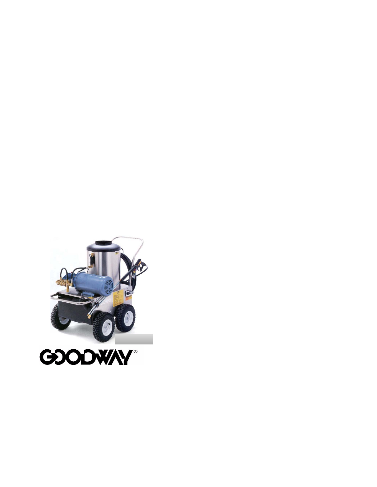
MODELS HPW-1000, HPW-2000 &
HPW-2000-3 ELECTRIC POWERED
&
MODEL HPW-1500G
GASOLINE POWERED
HOT WATER
PRESSURE WASHERS
OPERATING AND MAINTENANCE
INSTRUCTIONS
HPW-2000-3

INTRODUCTION
Thank you for purchasing this Goodway Hot Water Pressure
Washer. We appreciate your business and look forward to serving
you in the future. As with all Goodway products, you can be
assured that the finest quality components and workmanship have
gone into this machine.
Please take a few minutes to read the following Operating and
Maintenance Instructions. By carefully following the instructions,
you will obtain years of trouble free service from this product.
Please pay particular attention to the safety instructions and
exercise caution when using this machine.
We are here to serve you!
For Sales call
1-800-333-7467
For Service call
1-800-370-2855
Goodway Technologies Corp.
Goodway reserves the right to improve products; contact the factory for the
latest configuration and uses.
Copyright 2000 Goodway Technologies Corp., Stamford, CT, U.S.A.
Effective Date: February 1, 2000
Goodway is a registered trademark of Per K. Reichborn
1
1

QUICK REFERENCE USER GUIDE
1. Read all instructions before using this product.
2. Check oil and fuel levels before starting unit.
3. For best results, use #1 or #2 fuel oil or diesel fuel to fire the
burner.
4. Always purge the water hose before connecting it to the water
inlet and make sure the screen washer is in place to prevent
debris from entering the system.
5. Trigger the gun for a few minutes before starting the unit to
relieve any air in the system.
6. Chemical application/rinse selection is accomplished by
twisting the side handle on the wand.
7. Do not change or tamper with any factory settings of the
components on these unit.
8. Do not run the pump dry.
9. Do not run without spraying for more than 2 minutes.
10. Do not allow water to freeze in the machine. Fill unit with
antifreeze if storing in freezing conditions.
11. Allow cold water to run through the coil before shutting the
machine down. Allow the machine to cool gradually.
12. Be careful of hot surfaces, hoses, wands, nozzles and fitting.
2
2

IMPORTANT SAFETY
INSTRUCTIONS
WARNING - When using this product basic precautions should
always be followed, including the following:
1. Read all the instructions before using the product.
2. To reduce the risk of injury, close supervision is
necessary when this product is used near children.
3. Know how to stop the product and bleed pressures
quickly. Be thoroughly familiar with the controls.
4. Stay alert - watch what you are doing.
5. Do not operate the product when fatigued or under
the influence of alcohol or drugs.
6. Keep operating area clear of all persons.
7. Do not overreach or stand on unstable support.
Keep good footing and balance at all times. Use
only certified scaffolding when necessary.
8. Follow the maintenance instructions specified in the
manual.
9. Do not operate without eye protection.
10. Follow the maintenance instructions specified in the
manual.
11. Use only Goodway recommended attachments.
12. BURN HAZARD: Do not touch the boiler housing
or metal part of wand when operating unit in the
hot wash mode. The use of insulated gloves will
help avoid accidental burns.
WARNING - Risk of Injection or Injury - Do Not Direct
Discharge Stream At Persons. This product is to be used only by
trained operators.
3
3

MODELS
HPW-1000, HPW-2000 & HPW-2000-3
ELECTRIC POWERED
SAVE THESE INSTRUCTIONS
GROUNDING INSTRUCTIONS
This product must be grounded. If it should malfunction or break
down, grounding provides a path of least resistance for the electric
current to reduce the risk of electric shock. This product is
equipped with a cord having an equipment-grounding conductor
and a grounding plug. The plug must be plugged into an
appropriate outlet that is properly installed and grounded in
accordance with all local codes and ordinances.
DANGER - Improper connection of the equipment-grounding
conductor can result in a risk of electrocution. Check with a
qualified electrician or service personnel if you are in doubt as to
whether the outlet is properly grounded. Do not modify the plug
provided with the product - if it will not fit the outlet, have a
proper outlet installed by a qualified electrician. Do not use any
type of adapter with this product.
EXTENSION CORDS
Use only 3-wire extension cords that have 3-prong grounding-type
plugs and 3-pole cord connectors that accept the plug from the
product. Use only extension cords that are intended for outdoor
use. These extension cords are identified by a marking
"Acceptable for use with outdoor appliances; store indoors while
not in use." Use only extension cords having an electrical rating
not less than the rating of the product. Do not use damaged
extension cords. Examine extension cords before using and
4
4

replace if damaged. Do not abuse extension cord and do not yank
on any cord to disconnect. Keep cord away from heat and sharp
edges. Always disconnect the extension cord from the receptacle
before disconnecting the product from the extension cord.
WARNING - To reduce the risk of electrocution, keep all
connections dry and off the ground. Do not touch plug with wet
hands.
CAUTIONS
1. Avoid exposing the machine to freezing temperatures as the
pump housing and heating coil may crack if water is allowed to
freeze in the unit. If the unit must be exposed to freezing
conditions, follow the instructions under COLD WEATHER
STORAGE.
2. DO NOT RUN THE PUMP DRY FOR MORE THAN 15
SECONDS.
3. When the pump is running without spraying, the bypass valve
allows the water to circulate around the pump. This condition
will gradually elevate the temperature through friction. Frequent
or prolonged bypass can result in high temperature build-up.
These high temperatures can cause premature failure of the
pump. RUNNING THE PUMP WITHOUT SPRAYING FOR
MORE THAN A FEW MINUTES IS NOT RECOMMENDED.
Do not attempt to change the factory settings of the bypass
valve or the nozzle orifice size. Doing so may create an unsafe
condition and shorten the life of the pump.
4. Do not spray water onto the machine housing or into the boiler
as serious damage can result, voiding the warranty.
5. Do not smoke while filling fuel tank. Do not use this product
where flammable liquids or vapors are present.
5
5

ELECTRIC MOTOR
The HPW-1000 is powered by a 1.5 HP (1.1 kW), 115 V, 60 HZ,
single phase electric motor. The HPW-2000 is powered by a 3 HP
(2.2 kW), 220 V, 60 HZ, single phase electric motor. The HPW2000-3 is powered by a 5 HP (3.7 kW), 220 V, 60 HZ, three phase
electric motor. The HPW-1000 and HPW-2000 are equipped with
thermal overload protection. The motor drives a three-plunger oil
bath pump. Should the motor overheat, the thermal overload will
cut off power to the motor. The overload is manually reset. The
reset button is located on the side of the motor. ALWAYS
DETERMINE AND CORRECT THE CAUSE OF THERMAL
OVERLOAD BEFORE USING THE MACHINE AGAIN.
NOTE: The HPW-2000-3 is not equipped with thermal overload
protection.
ABOUT THE OIL BURNER/BOILER
These units are equipped with an oil-fired boiler, which can be
fired on #1 or #2 fuel oil or diesel fuel. Kerosene is not
recommended. Most burner service can be performed locally by a
qualified oil burner service technician.
NEVER REMOVE THE BURNER HOUSING FROM THE
UNIT AS DAMAGE TO THE BOILER INSULATION WILL
RESULT. ALL BURNER SERVICE CAN BE PERFORMED
WITH THE BURNER HOUSING IN PLACE.
WARNING
: NEVER PUT GASOLINE IN THE BURNER
FUEL TANK.
WARNING
: DO NOT WRAP HOSES OR ELECTRICAL
CORDS AROUND THE BOILER HOUSING. DAMAGE
AND SERIOUS INJURY MAY RESULT
6
6

BOILER/BURNER SAFETY - ALL MODELS
1. Keep combustible materials a minimum of 48" (1200 mm)
from the sides of the boiler housing.
2. Do not install a stack pipe on this product as it will impede
airflow resulting in poor combustion and possible release of
harmful fumes.
3. Do not exhaust gasses into a wall, ceiling, or confined space.
4. The use of a ducted exhaust hood is recommended for indoor
operation. Otherwise, place the power unit outside the
building. Do not, however, expose the machine to rain.
5. Always be mindful that there is an open flame at the top of the
boiler when the burner is firing. Keep hands, hair, clothing and
other combustible materials away.
FUEL OIL FILTER
These machines are equipped with a micron fuel oil filter, which is
located on the fuel oil line under the machine housing. The fuel oil
tank is also equipped with a filter to trap larger pieces of debris,
which may get into the fuel oil supply. The micron filter should be
changed and the fuel oil tank cleaned annually.
7
7

HEATING COIL
The heating coil in the boiler is constructed of high quality 1/2"
(13mm) ID Sch. 80 steel tubing for long service. Proper care of
the coil will maximize its life. Care should be taken to prevent
objects from falling into the heating coil. Such objects could cause
poor burner performance. In cases where very hard water is used,
mineral scale can build up and restrict the water flow through the
coil. It may be necessary to descale the coil annually. A coil
descaler (part # HPW-DSC) is available from Goodway
Technologies Corp.
PUMP LUBRICATION
These units are equipped with an oil bath pump. When shipped,
the crankcase is filled with the proper amount of oil. Due to the
possibility of spillage in shipment, the oil level should be checked
prior to the first use of the machine, as well as prior to each use.
With the machine resting on a level surface, the correct oil level
should reach the middle of the sight glass on the side of the pump.
If the oil level is low, add sufficient oil to the crankcase. DO NOT
OVERFILL.
The high-pressure pump crankcase takes Cat Pump Oil or premium
10W30 hydraulic oil (not motor oil). Cat Pump Oil (HPW-CPO)
is available from Goodway Technologies Corp.
CHANGING PUMP OIL
Pump oil should be changed after the first 50 hours of operation
and then after every 50 -100 hours.
8
8

GETTING READY
1. Check all oil level before any operation to ensure good start up
and problem free performance.
2. Connect a clean water hose capable of delivering 2 GPM (7.6
LPM) for the HPW-1000, 2.2 GPM (8.3 LPM) for the HPW2000, or 4 GPM (15.1 LPM) for the HPW-2000-3 to the garden
hose fitting located on the pump inlet. Make sure the screen
washer is clean and in place. Consult the Goodway catalog for
heavy-duty water supply hose (part # WSH-R50).
NOTE: Any restriction in the water supply may cause
cavitation and pump damage. Positive inlet pressure above 25
PSI (1.7 BAR) is required to avoid cavitation. DO NOT RUN
DRY.
3. Connect the high-pressure hose to the outlet fitting located on
the side of the boiler housing.
4. Connect the gun to the high-pressure hose.
5. Insert the dip tube into a container of soap or chemical, if used.
See " SOAP OR CHEMICAL APPLICATION" for a more
detailed explanation on using soap or chemicals.
6. Turn on the water supply, and with no quick disconnect nozzle
in place, trigger the gun for a few minutes to allow trapped air,
dirt particles or mill scale to escape from the system. Reinstall
the desired quick disconnect nozzle.
NOTE: Always be sure when operating the machine that the
nozzle is not clogged or restricted in any way.
CAUTION: ALWAYS ENGAGE THE TRIGGER LOCK WHEN
CHANGING NOZZLES.
9
9

OPERATION
These models are equipped with a three-position switch:
Position #1 - off position.
Position #2 - pump on for cold water washing
Position #3 - burner on for hot water washing
1. Trigger the gun and turn the main switch to position #2. Allow
the unit to attain full pressure.
2. If desired, turn the main switch to position #3 for hot water
washing.
The Goodway Hot Water Pressure Washers use a double wand
with a low pressure nozzle for chemical application mounted on
one wand and a fitting for quick disconnect high pressure nozzles
on the other. The units are supplied with 4 quick disconnect
nozzles - a 0o pinpoint spray, a 15o fan spray, a 25o fan spray and
a 40o fan spray. The low-pressure nozzle activates the siphon
injector to draw soap or chemical into the water stream. The highpressure nozzles are used for rinsing. To switch from one nozzle
to another simply:
1. Release the trigger to stop the spray action and engage the
trigger lock.
2. Pull back the locking collar to release the nozzle.
3. Insert another nozzle until the locking collar snaps into place.
CAUTION: NOZZLES MAY BE HOT.
SOAP OR CHEMICAL APPLICATION
1. Place the strainer end of the siphon hose into your container of
premixed chemical solution. The siphon injector draws at a
rate of 1 part chemical to 8 parts water when the soap valve is
wide open. Dilute your chemical, if necessary, to the proper
level to obtain the final ratio recommended by the chemical
10
10

manufacturer. ALWAYS USE LIQUID CONCENTRATES
TO PREVENT CLOGGING THE SIPHON INJECTOR.
2. Chemicals are applied at low pressure and are drawn through
the water system of the machine. Application is controlled by
the valve on the wand. Turning the handle on the left side of
the wand counter clockwise (or away from you) will start and
gradually increase the chemical draw. Turning the handle
clockwise (or towards you) will decrease and eventually shut
off the chemical draw. It takes several seconds for the
chemical to travel through the boiler coil and high-pressure
hose to the nozzle. Chemical application is not instantaneous
and chemical spray continues for several seconds after
switching to high pressure.
SHUTDOWN
When shutting down from hot water operation, allow the boiler to
cool gradually. Move the main switch to the cold water washing
position (#2 ) and leave the gun trigger open for a few minutes
before turning the machine completely off. Once the unit is turned
off, trigger the gun to relieve pressure.
COLD WEATHER STORAGE
If the machine must be stored in an area subject to freezing
temperatures, observe the following instructions:
1. Prepare a five-gallon pail with at least three gallons of anti-
freeze mixture.
2. Run a feed hose from the pail to the pump inlet.
3. Place the end of the wand in the pail and trigger the gun.
4. Run the unit in the cold water wash mode until the anti-freeze
mixture is seen discharging from the wand. The machine,
hose, gun and wand are now protected
against freezing.
11
11

PUMP REPAIRS
When pump repairs are required, the pump, bypass valve and
plumbing can be removed from the unit and sent to the factory for
repair. Customer repair of the pump is not recommended as
improper reassembly of the pump can result in an unsafe condition.
In addition, often times problems that seem to be pump related are
caused by faulty bypass valves or other components in the pressure
system. It is not necessary to return the entire machine to have
pump repairs performed.
FACTORY REPAIR OF THE BYPASS VALVE IS
RECOMMENDED. IF THE BYPASS VALVE IS NOT
PROPERLY ADJUSTED, PUMP DAMAGE CAN RESULT.
NEVER CHANGE THE FACTORY SETTING OF THE
BYPASS VALVE.
TROUBLESHOOTING
Problem Probable Causes Remedy
Pump runs Water not turned on Turn on water
but no spray Screen washer clogged Clean washer
Spray nozzle clogged Clean nozzle
Water comes Siphon injector clogged Clean siphon
out of dip tube injector
Ball and/or spring missing Check for proper
assembly
Will not draw Siphon injector clogged Clean siphon
chemical soap injector
Pressure too high Switch to low
pressure nozzle
Pressure and/ Worn or damaged nozzle Replace nozzle
or flow drops Fouled inlet strainer Clean strainer
12
12

Problem Probable Causes Remedy
Pressure and/ Worn or damaged hose Repair or replace
or flow drops hose
Cavitation (knocking Check suction
sound in pump) line on pump
inlet for
restrictions
Leakage in the hi pressure Check all
stream connections for
leaks
Pump damaged Return pump for
repair
Pump oil Water in crankcase Return pump for
milky new seals
Noisy Worn pump bearings Return pump for
operation Cavitation repair
Rough/ Bypass valve failure Replace bypass
pulsating valve
operation Pump damage Return pump for
repair
Pump pressure Restricted discharge Resize discharge
as rated, pres- plumbing to flow rate of
sure drop at pump
gun
Motor stops Overloaded due to long Unplug and let
run without spraying motor cool
down. Once
cool, reset
thermal overload
on side of motor
13
13

Problem Probable Causes Remedy
Motor stops Extension cord too Change extension
long or inadequate size cord
Fuse blown Plug into
adequately fused
outlet
Burner will Dirty burner nozzle Clean nozzle
not ignite
Empty fuel oil tank Fill with fuel oil
Switch in cold wash Switch to hot
position wash position
Burner failure Consult a
qualified service
technician
Flow switch not activating Test/replace
Thermal switch open Test/replace
Black smoke Burner nozzle worn Replace nozzle
from burner High elevation Consult factory
Bad fuel Replace with clean
fuel after cleaning
fuel tank
White/gray Bad fuel Replace with clean
smoke from fuel after cleaning
burner fuel tank
Clogged fuel nozzle Clean nozzle
Inlet oil line air leak Locate and repair leak
Bad igniter Replace igniter
Burner inlet air wrong Adjust inlet air (this is
the last thing to be
done)
Pump makes Insufficient water supply Check water flow rate
knocking to the unit. Must be
sound greater than machine
rating.
14
14

PARTS LIST - MODEL HPW-1000, -2000, -2000-3
Key # Part # QDescription ty.
1 GPW-DWA-Q 1 Double wand with
quick disconnect
2 1225 1 Low pressure nozzle
3 2701 1 Nozzle holder
4 2509 4 Grommets
*5 QDN-0004R 1 Quick disconnect
*5 QDN-1504Y 1 Quick disconnect
nozzle -15
o
*5 QDN-2504G 1 Quick disconnect
nozzle -25o
*5 QDN-4004W 1 Quick disconnect
**5 QDN-00055R 1 Quick disconnect
**5 QDN-15055Y 1 Quick disconnect
nozzle -15
o
**5 QDN-25055G 1 Quick disconnect
nozzle -25o
**5 QDN-40055W 1 Quick disconnect
nozzle -40
o
nozzle -40
o
6 2702 1 Wand rest
7 1024-50H 1 High pressure hose –
50'
8 2744 2 Male disconnect
fitting
9 2745 2 Female disconnect
fitting
10 2705 1 Bypass hose
11 2706 1 Water Fitting
12 2707 2 Hose barb
13 2708 1 Bypass valve
14 2709 1 Elbow
15 2710 1 Connector hose
16 2711 1 Siphon injector
17 2712 1 Siphon hose
15
15

Key # Part # QDescription ty.
18 1039 1 Siphon hose strainer
19 2714 1 Motor connector cord
20 2715 2 Elbow
21 2716 1 Flow switch
22 2717 1 Nipple
23 2718 1 Filter screen
24 2719 1 Pump (HPW-1000)
24 2719A 1 Pump (HPW-2000)
24 2719-3 1 Pump (HPW-2000-3)
25 2720 1 Motor (HPW-1000)
25 2720A 1 Motor (HPW-2000)
25 2720A-3 1 Motor (HPW-2000-3)
26 2721 1 Front handle
27 2722 2 Cord restrainer
28 2615 1 Power cord
29 2724 4 Wheel
30 2725 1 Fuel oil tank cap
31 2726 1 Fuel oil tank
32 2727 1 Main switch
HPW-1000
32 2727A 1 Main switch
HPW-2000
32 2727A-3 1 Main switch
HPW-2000-3
33 2728 2 Fuel oil line
34 2729 1 Fuel oil filter
35 2730 1 Oil burner
36 2731 1 Chassis
37 2732 1 Rear cover
38 HWW-25 2 Washer
39 HWS-M1037H 2 Screw
40 2733 1 Hose hook
41 2734 1 Insulation
42 2735 1 Liner
43 2736 1 Coil
44 2737 1 Lid, coil
16
16

Key # Part # QDescription ty.
45 2738 1 Rear handle
46 2739 1 Drain hose
47 2740 1 Pressure relief valve
HPW-1000
47 2740-2 1 Pressure relief valve
HPW-2000
48 2741 1 Fitting, pressure relief
valve
49 2742 1 Cross
50 2743 1 Thermal overload
valve
51 2730-1 1 Transformer
* For HPW-1000 & HPW-2000
** For HPW-2000-3
17
17

18
18

19
19

20
20

MODEL
HPW-1500G
GASOLINE POWERED
SAVE THESE INSTRUCTIONS
CAUTIONS
1. Avoid exposing the machine to freezing temperatures as the
pump housing and heating coil may crack if water is allowed
to freeze in the unit. If the unit must be exposed to freezing
conditions, follow the instructions under COLD WEATHER
STORAGE.
2. DO NOT RUN THE PUMP DRY FOR MORE THAN 15
SECONDS.
3. When the pump is running without spraying, the bypass valve
allows the water to circulate around the pump. This condition
will gradually elevate the temperature through friction.
Frequent or prolonged bypass can result in high temperature
build-up. These high temperatures can cause premature failure
of the pump.
4. Do not attempt to change the factory settings of the bypass
valve or the nozzle orifice size. Doing so may create an unsafe
condition and shorten the life of the pump.
5. Do not spray water onto the machine housing or into the boiler
as serious damage can result, voiding the warranty.
6. Do not smoke while filling fuel tanks. Do not use this product
where flammable liquids or vapors are present.
21
21

GASOLINE ENGINE
The Model HPW-1500G is equipped with a Briggs & Stratton 6
HP (4.5 kw) Vanguard single cylinder engine that drives a three
plunger oil bath pump. The operator should become familiar with
the information contained in the Briggs & Stratton Operating
and Maintenance Instructions enclosed with this machine.
Engine repairs and warranty service are available directly from
your nearest Briggs & Stratton Service Center, which is listed in
the Yellow Pages under "Engines, Gasoline" or "Gasoline
Engines".
NOTE: DO NOT RUN THE ENGINE WITHOUT THE AIR
FILTER IN PLACE. DO NOT ATTEMPT TO CHANGE THE
FACTORY SETTINGS OF THE ENGINE R.P.M. DOING SO
MAY CREATE AN UNSAFE CONDITION AND SHORTEN
ENGINE AND PUMP LIFE.
BATTERY
The model HPW-1500G requires a fully charged 12-volt series 26
automotive battery for proper burner operation. The unit is not
shipped equipped with a battery. Install a battery before
attempting to use the machine. DO NOT OPERATE WITHOUT
A BATTERY!!
ABOUT THE OIL BURNER/BOILER
The HPW-1500G is equipped with an oil-fired boiler, which can
be fired on #1 or #2 fuel oil or diesel fuel. Kerosene is not
recommended.
Most burner service can be performed locally by a qualified oil
burner service technician. NEVER REMOVE THE BURNER
HOUSING FROM THE UNIT AS DAMAGE TO THE BOILER
INSULATION WILL RESULT. ALL BURNER SERVICE CAN BE
PERFORMED WITH THE BURNER HOUSING IN PLACE.
22
22

WARNING: NEVER PUT GASOLINE IN THE BURNER FUEL
TANK.
WARNING: DO NOT WRAP HOSES OR ELECTRICAL
CORDS AROUND THE BOILER HOUSING. DAMAGE AND
SERIOUS INJURY MAY RESULT
BOILER/BURNER SAFETY
1. Keep combustible materials a minimum of 48" (1200 mm)
from the sides of the boiler housing.
2. Do not install a stack pipe on this product as it will impede
airflow resulting in poor combustion and possible release of
harmful fumes.
3. Do not exhaust gasses into a wall, ceiling, or confined space.
4. The use of a ducted exhaust hood is recommended for indoor
operation. Otherwise, place the power unit outside the
building. Do not, however, expose the machine to rain.
5. Always be mindful that there is an open flame at the top of the
boiler when the burner is firing. Keep hands, hair, clothing
and other combustible materials away.
FUEL OIL FILTER
The HPW-1500G is equipped with a micron fuel oil filter, which is
located on the fuel oil line under the machine housing. The fuel oil
tank is also equipped with a filter to trap larger pieces of debris,
which may get into the fuel oil supply. The micron filter should be
changed and the fuel oil tank cleaned annually.
23
23

HEATING COIL
The heating coil in the boiler is constructed of high quality 1/2"
Sched. 80 steel tubing for long service. Proper care of the coil will
maximize its life. Care should be taken to prevent objects from
falling into the heating coil. Such objects could cause poor burner
performance. In cases where very hard water is used, mineral
scale can build up and restrict the water flow through the coil. It
may be necessary to descale the coil annually. A coil descaler
(part # HPW-DSC) is available from Goodway Technologies Corp.
PUMP LUBRICATION
The HPW-1500G is equipped with an oil bath pump. When
shipped, the crankcase is filled with the proper amount of oil. Due
to the possibility of spillage in shipment, the oil level should be
checked prior to the first use of the machine, as well as prior to
each use.
With the machine resting on a level surface, the correct oil level
should reach the middle of the sight glass on the side of the pump.
If the oil level is low, add sufficient oil to the crankcase. DO NOT
OVERFILL.
The high-pressure pump crankcase takes 30W non-detergent
motor oil.
CHANGING PUMP OIL
Pump oil should be changed after the first 50 hours of operation
and then after every 50 -100 hours..
24
24

GETTING READY
1. Check all oil and fuel levels before any operation to ensure
good start up and problem free performance.
2. Connect a clean water hose capable of delivering 4 GPM
(15.1 LPM) to the garden hose fitting located on the pump
inlet. Make sure the screen washer is clean and in place.
Consult the Goodway catalog for heavy-duty water supply
hose (part # WSH-R50).
NOTE: Any restriction in the water supply may cause cavitation
and pump damage. Positive inlet pressure above 25 PSI (1.7 BAR)
is required to avoid cavitation. DO NOT RUN DRY.
3. Connect the high-pressure hose to the outlet fitting located on
the side of the boiler housing.
4. Connect the gun to the high-pressure hose using the fitting.
5. Insert the dip tube into a container of soap or chemical, if
used. See " SOAP OR CHEMICAL APPLICATION" for a
more detailed explanation on using soap or chemicals.
6. Turn on the water supply, and with no quick disconnect
nozzle in place, trigger the gun for a few minutes to allow
trapped air, dirt particles or mill scale to escape from the
system. Reinstall the desired quick disconnect nozzle.
NOTE: Always be sure when operating the machine that the
nozzle is not clogged or restricted in any way.
CAUTION: ALWAYS ENGAGE THE TRIGGER LOCK
WHEN CHANGING NOZZLES.
25
25

OPERATION
The HPW-1500G is equipped with a four-position switch:
Position #1 - off position
Position #2 - engine start up
Position #3 - cold water washing/battery charging
Position #4 - hot water washing
There are two indicator lamps located at the switch. The red lamp
while switch is in position 3 or 4 indicates a problem in the
charging circuit and the green lamp indicates activation of the
burner controls and will light up when the burner is firing.
1. Review engine starting instructions in the Briggs & Stratton
Manual provided with the machine.
2. Turn the main switch to position #2, trigger the gun and start
the engine. Failure to trigger may result in belt breakage.
Wait for the engine to get up to speed and begin running
smoothly
3. Switch to position #3 for cold water washing or position #4 for
hot water washing. Operating in position #3 activates the
battery charging system.
WARNING: NEVER START THE MACHINE WITH THE
SWITCH IN POSITION #3 OR POSITION #4. THIS WILL
DAMAGE THE MACHINE AND VOID THE WARRANTY.
The Goodway Hot Water Pressure Washers use a double wand
with a low pressure nozzle for chemical application mounted on
one wand and a fitting for quick disconnect high pressure nozzles
on the other. The units are supplied with 4 quick disconnect
nozzles - a 0o pinpoint spray, a 15o fan spray, a 25o fan spray and
a 40o fan spray. The low-pressure nozzle activates the siphon
injector to draw soap or chemical into the water stream. The highpressure nozzles are used for rinsing. To switch from one nozzle
to another simply:
26
26

1. Release the trigger to stop the spray action and engage the
trigger lock.
2. Pull back the locking collar to release the nozzle.
3. Insert another nozzle until the locking collar snaps into place.
CAUTION: NOZZLES MAY BE HOT.
SOAP OR CHEMICAL APPLICATION
1. Place the strainer end of the siphon hose into your container of
premixed chemical solution. The siphon injector draws at a
rate of 1 part chemical to 8 parts water when the soap valve is
wide open. Dilute your chemical, if necessary, to the proper
level to obtain the final ratio recommended by the chemical
manufacturer. ALWAYS USE LIQUID CONCENTRATES
TO PREVENT CLOGGING THE SIPHON INJECTOR.
2. Chemicals are applied at low pressure and are drawn through
the water system of the machine. Application is controlled by
the valve on the wand. Turning the T-handle on the left side of
the wand counter clockwise (or away from you) will start and
gradually increase the chemical draw. Turning the handle
clockwise (or towards you) will decrease and eventually shut
off the chemical draw. It takes several seconds for the
chemical to travel through the boiler coil and high-pressure
hose to the nozzle. Chemical application is not instantaneous
and chemical spray continues for several seconds after
switching to high pressure.
27
27

SHUTDOWN
When shutting down from hot water operation, allow the boiler to
cool gradually. Move the main switch to the cold water washing
position (#3 ) and leave the gun trigger open for a few minutes
before turning the machine completely off. Once the unit is turned
off, trigger the gun to relieve pressure.
COLD WEATHER STORAGE
If the machine must be stored in an area subject to freezing
temperatures, observe the following instructions:
1. Prepare a five-gallon pail with at least three gallons of anti-
freeze mixture.
2. Run a feed hose from the pail to the pump inlet.
3. Place the end of the wand in the pail and trigger the gun.
4. Run the unit in the cold water wash mode until the anti-freeze
mixture is seen discharging from the wand. The machine,
hose, gun and wand are now protected against freezing.
PUMP REPAIRS
When pump repairs are required, the pump, bypass valve and
plumbing can be removed from the unit and sent to the factory for
repair. Customer repair of the pump is not recommended as
improper reassembly of the pump can result in an unsafe condition.
In addition, often times problems that seem to be pump related are
caused by faulty bypass valves or other components in the pressure
system. It is not necessary to return the entire machine to have
pump repairs performed.
FACTORY REPAIR OF THE BYPASS VALVE IS
RECOMMENDED. IF THE BYPASS VALVE IS NOT PROPERLY
ADJUSTED, PUMP DAMAGE CAN RESULT. NEVER CHANGE
THE FACTORY SETTING OF THE BYPASS VALVE.
28
28

TROOUBLESHOOTING - GENERAL
Problem Probable Causes Remedy
Pump runs Water not turned on Turn on water
but no spray Screen washer clogged Clean washer
Spray nozzle clogged Clean nozzle
Water comes Siphon injector clogged Clean siphon out of
dip tube injector
Ball and/or spring missing Check for proper
from siphon injector assembly
Will not draw Siphon injector clogged Clean siphon
chemical injector
Pressure too high Switch to low
pressure nozzle
Pressure and/ Worn or damaged nozzle Replace nozzle
or flow drops
Fouled inlet strainer Clean strainer
Worn or damaged hose Repair or replace
hose
Cavitation (knocking Check suction
sound in pump) line on pump
inlet for
restrictions
Pressure and/ Leakage in the hi pressure Check all
flow drops stream connections for
leaks
Pump damaged Return pump for
repair
Pump oil Water in crankcase Return pump
for milky new seals
29
29

Problem Probable Causes Remedy
Knocking Insufficient water supply Increase water supply
Sound
Rough\puls- Bypass valve failure Replace bypass
ating operation valve
with pressure Pump damage Return pump for
drop repair
Pump pressure Restricted discharge Resize discharge
as rated, to flow rate of
pressure drop pump
at gun
Engine will Out of fuel Fill fuel tank
not start
Fuel valve shut off Open valve
Engine oil low Check oil
level and
add to full
Engine stops Out of fuel Fill fuel
tank
Low oil Check oil
level and
add to full
Burner will If green signal light is on:
not ignite Dirty burner nozzle Clean nozzle
Empty fuel oil tank Fill with fuel
oil
Burner failure Consult a
qualified
service
technician
30
30

Problem Probable Causes Remedy
Burner will If green signal light is not on:
not ignite Switch in cold wash position Switch to hot
wash position
Flow switch or temperature Replace flow
sensor failed switch or
temperature
sensor
Black smoke Burner nozzle worn Replace nozzle
from burner High elevation Consult factory
Bad fuel Replace with clean
fuel after cleaning
fuel tank
White/gray Bad fuel Replace with clean
smoke from fuel after cleaning
burner fuel tank
Clogged fuel nozzle Clean nozzle
Inlet oil line air leak Locate and repair
leak
Bad igniter Replace igniter
Burner inlet air wrong Adjust inlet air
(this is the last
thing to be done)
Pump makes Insufficient water supply Check water flow
knocking rate to the unit
sound Must be greater.
than machine
rating
31
31

PARTS LIST - MODEL HPW-1500G
Key #
Part # QDescription ty.
1 GPW-DWA-Q 1 Double wand with
quick disconnect
2 1225 1 Low pressure nozzle
3 2701 1 Nozzle holder
4 2509 4 Grommets
5 QDN-0005R 1 Quick disconnect
5 QDN-1505Y 1 Quick disconnect
nozzle -15o
5 QDN-2505G 1 Quick disconnect
nozzle -25o
5 QDN-4005W 1 Quick disconnect
nozzle -40o
6 2702 1 Wand rest
7 1024-50H 1 High pressure hose –
25'
8 2744 2 Male disconnect
fitting
9 2745 2 Female disconnect
fitting
11 2801 1 Water Fitting
13 2802 1 Bypass valve
14 2803 1 Alternator
15 2710 1 Connector hose
16 2711 1 Siphon injector
17 2712 1 Siphon hose
18 1039 1 Siphon hose strainer
19 2806 1 Pulley, alternator
20 2715 2 Elbow
21 2716 1 Flow switch
22 2717 1 Nipple
23 2718 1 Filter screen
*24 2844 1 Pump (cat)
25 2501 1 Engine
32
32

Key # Part # QDescription ty.
26 2721 1 Front handle
27 2805 1 Belt
*28 2843 1 Pump Pulley
29 2807 4 Wheel
30 2725 1 Fuel oil tank cap
31 2726 1 Fuel oil tank
32 2808 1 Main switch
33 2728 2 Fuel oil line
34 2729 1 Fuel oil filter
35 2809 1 Oil burner
36 2810 1 Chassis
37 2732 1 Rear cover
38 HWW-25 2 Washer
39 HWS-M1037H 2 Screw
40 2733 1 Hose hook
41 2734 1 Insulation
42 2735 1 Liner
43 2736 1 Coil
44 2737 1 Lid, coil
45 2738 1 Rear handle
46 2739 1 Drain hose
47 2811 1 Pressure relief valve
48 2741 1 Fitting, pressure relief
valve
49 2742 1 Cross
50 2743 1 Thermal overload
valve
51 2812 1 Tee
52 2813 1 Relay
53 2809 1 Transformer
*For Models manufactured before December 1999 use pump p/n
2804 and p/n 2806 for pulley.
33
33

34
34

35
35

36
36
We Are Here to Serve You!
For Sales Call: 1-800-333-7467
For Service Call: 1-800-370-2855
Goodway Technologies Corporation
manufactures and distributes a complete
line of Tube/Pipe Cleaning Systems, Duct
Cleaning Systems, Vacuums, Floor
Machines, Hi-Pressure Washers and other
maintenance related equipment.
GOODWAY TECHNOLOGIES CORPORATION
420 WEST AVENUE, STAMFORD,CT 06902, USA
Tel: 203-359-4708 · Toll-Free Tel: 800-243-7932
Fax: 203-359-9601 ·Toll-Free Fax: 800-359-9625
E-Mail: goodway@goodway.com
Internet: www.goodway.com
 Loading...