

Goodway GLS-150, GLS-200, GLS-260 User Manual
High Speed CNC Turning Centers
GLS-150
SERIES
HIGH SPEED CNC TURNING CENTERS
Packed with industry leading technology and top quality components, the Goodway GLS series
turning centers combine power, strength, and speed to bring you The Ultimate Machining
Power®. These high speed machines will easily accomplish the demanding turning applications
of today and tomorrow. Furthermore, with optional live tooling, C-axis, and Y-axis, milling, turning
applications can be completed in one single machine.
GLS Series Construction Spindle Turret Multi-Tasking
30˚ slant-bed design provides smooth chip
disposal and easier operator access.
Steel way covers and special steel wipers
molded with industrial strength rubber are
used for durability.
Fully enclosed splashguards keep chips and
coolant contained for a safe clean working
environment.
The auto lubrication system delivers
metered amounts of lubrication to the slide
ways, ball screws, and vital components.
Distribution is automatically shut o
during idling to prevent waste.
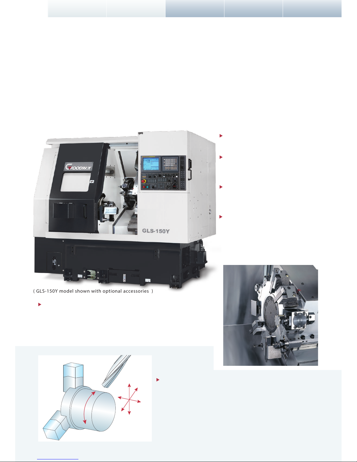
Y-axis models perform virtually the same way as machining centers
equipped with 4
th
-axis rotary tables, but with the benet of built-in
turning capability. The X, Y, Z axes are like that of a machining center,
while the C-axis acts as the 4
th
-axis. This conguration replaces a turning
center and machining center equipped with 4
th
-axis with one machine,
thus, saving money, time, oor space, manpower and xture costs, while
reducing accuracy lost by eliminating the part from being moved to
another machine.
Y-axis
C-axis
X-axis
Z-axis
Live tooling and C-axis control capabilities on the GLS series allow the
machine to perform multiple tasks on a work-piece, such as turning,
milling, drilling and tapping. This can save manpower and reduce cycle
time, while reducing accuracy lost, which will occur if the part is moved
from one machine to another.
( GLS-150Y model shown with optional accessories )
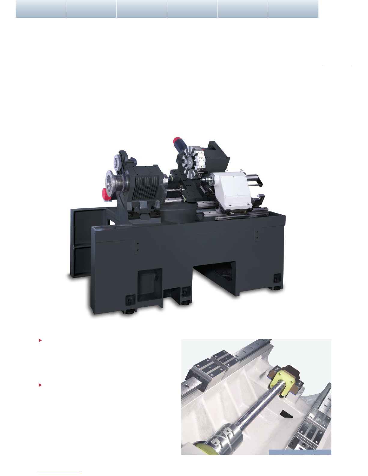
Built to withstand years and years of rigorous high production turning, the heavily
ribbed, one-piece, thermally balanced bed and casting parts are of “Meehanite”
casting. The 30 degrees true slant bed design further provides superior support for
the headstock, turret, and tailstock, thus, creating the rigidity needed for long-term
high precision turning and ecient chip removal.
MAXIMUM STRENGTH CONSTRUCTION
Major structural components have been combined into
one solid platform. The low center of gravity 30° slant
bed design provides the most rigid foundation possible
for the headstock, turret, and tailstock.
By using Finite Element Methods ( FEM ), optimal
reinforce ribbings are directly cast into the one-piece
bed structure. Mechanical rigidity has been increased
by more than 30% when compared to conventional
designs. The GLS series is capable of performing
heavy-duty turning and maintaining long-term
high-precision accuracy. More rigidity also means
extended tool life.
1
2
( Casting structure of GLS series shown )
Linear Guide Way & Ball Screw
Performance Quailty Features Automation Dimensions Specications

G
H
E
I
FD
C
B
M
N
O
S
K
J
Q
P
R
L
T
A
GLS Series Construction Spindle Turret Multi-Tasking
ULTIMATE TURNING POWER
The heavy-duty headstock is of one-piece casting reinforced with heat dispensing ns.
Standard rigid tapping feature provides high-speed precision tapping without the use of oating tap holders. Set-up is
easier and depth of thread more accurate, permitting maximum productivity for tapping operations.
The precision direct belt drive system provides greater spindle control, exibility and serviceability. Pulley ratios ne tune
the motor’s maximum RPM to match the spindle’s maximum RPM, which result in full output at the lowest RPM possible.
Thus, utilizing the full potential of the spindle motor for maximum cutting power.
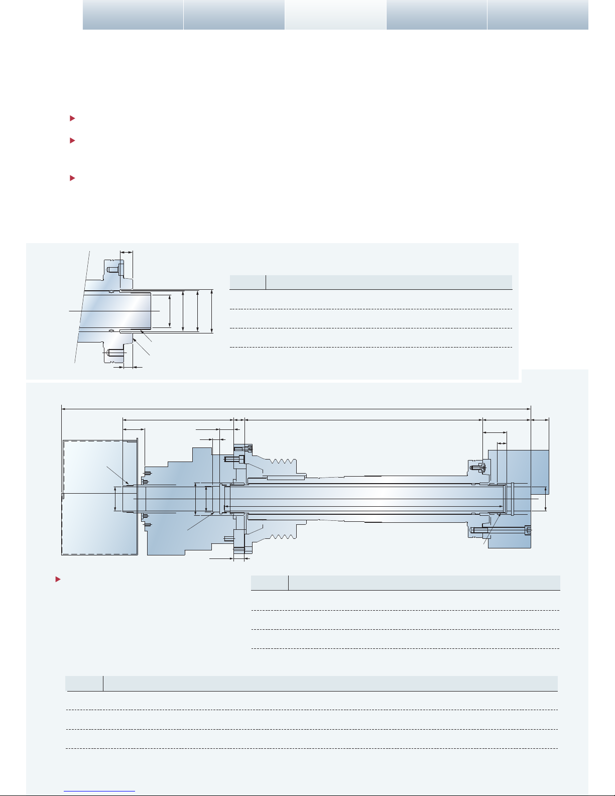
c: Draw Tube O.D. e: Spindle I.D. Stepd: Spindle I.D.b: Draw Tube I.D.
a
b c d e
f
g
h
Spindle & Nose Dimension Drawing
P4 grade ( Class 7 ) super-high precision bearings
are directly assembled for maximum level of
support and precision. Bearing conguration is
designed for heavy-duty cutting with
ultra-smooth performance and long term
durability with a higher level of accuracy.
Unit: mm
Unit: mm
25 Ø75 M85xP2.0 620 15 Ø95 Ø80 M85xP2.0 Ø75 M84xP1.5
Model
GLS-150
GLS-200
GLS-260
C ED F GBA
1,008 32 527.9 91 29
1,005 23 510 103 39
1,032 38 506.5 113 43
Model
GLS-150
GLS-200
GLS-260
H I J K L M O P Q R S TN
19 Ø45 M55xP2.0 629 15 Ø65 Ø50 M55xP2.0 Ø46 M52xP1.5
20.5 Ø52 M60xP2.0 597 15 Ø70 Ø55 M55xP2.0 Ø52 M58xP1.5
max: 40
min : 25
max: 30
min : 15
max: 15
min : 0
max: 47
min : 25
max: 219
min : 204
max: 238
min : 216
max: 45
min : 33
max: 52
min : 36.5
max: 58.5
min : 39.5
max: 275
min : 250
max: 35
min : 10
max: 25
min : 0
max: 30
min : 8
max: 22
min : 0
max: 50
min : 25
Model
GLS-150
GLS-200
GLS-260
c ed f g hba
22 Ø46 Ø55 Ø56 Ø60 M55xP2.0 A2-5 12.4
20 Ø52 Ø65 Ø66 Ø70 M60xP2.0 A2-6 14.3
20 Ø65.5 Ø75 Ø76 Ø110 M85xP2.0 A2-8 17.5
G
H
E
I
FD
C
B
M
N
O
S
K
J
Q
P
R
L
T
A
GLS Series Construction Spindle Turret Multi-Tasking
ULTIMATE TURNING POWER
The heavy-duty headstock is of one-piece casting reinforced with heat dispensing ns.
Standard rigid tapping feature provides high-speed precision tapping without the use of oating tap holders. Set-up is
easier and depth of thread more accurate, permitting maximum productivity for tapping operations.
The precision direct belt drive system provides greater spindle control, exibility and serviceability. Pulley ratios ne tune
the motor’s maximum RPM to match the spindle’s maximum RPM, which result in full output at the lowest RPM possible.
Thus, utilizing the full potential of the spindle motor for maximum cutting power.
c: Draw Tube O.D. e: Spindle I.D. Stepd: Spindle I.D.b: Draw Tube I.D.
a
b c d e
f
g
h
Spindle & Nose Dimension Drawing
P4 grade ( Class 7 ) super-high precision bearings
are directly assembled for maximum level of
support and precision. Bearing conguration is
designed for heavy-duty cutting with
ultra-smooth performance and long term
durability with a higher level of accuracy.
Unit: mm
Unit: mm
25 Ø75 M85xP2.0 620 15 Ø95 Ø80 M85xP2.0 Ø75 M84xP2.0
Model
GLS-150
GLS-200
GLS-260
C ED F GBA
1,008 23 505.1 91 37
1,005 38 510.3 103 38
1,005 38 510.3 113 43
Model
GLS-150
GLS-200
GLS-260
H I J K L M O P Q R S TN
20 Ø52 M60xP2.0 590 15 Ø70 Ø55 M60xP2.0 Ø52 M58xP1.5
20 Ø66 M74xP2.0 620 15 Ø95 Ø80 M85xP2.0 Ø75 M84xP2.0
max: 47
min : 25
max: 30
min : 8
max: 22
min : 0
max: 50
min : 25
max: 238.5
min : 260.5
max: 250
min : 275
max: 46
min : 34
max: 51.5
min : 35.5
max: 58.5
min : 39.5
max: 275
min : 250
max: 35
min : 10
max: 25
min : 0
max: 35
min : 10
max: 25
min : 0
max: 50
min : 25
Model
GLS-150
GLS-200
GLS-260
c ed f g hba
22 Ø52 Ø60 Ø61 Ø67 M60xP2.0 A2-5 12.3
20 Ø65.5 Ø75 Ø76 Ø82 M74xP2.0 A2-6 14.3
20 Ø65.5 Ø75 Ø76 Ø110 M85xP2.0 A2-8 17.5
3
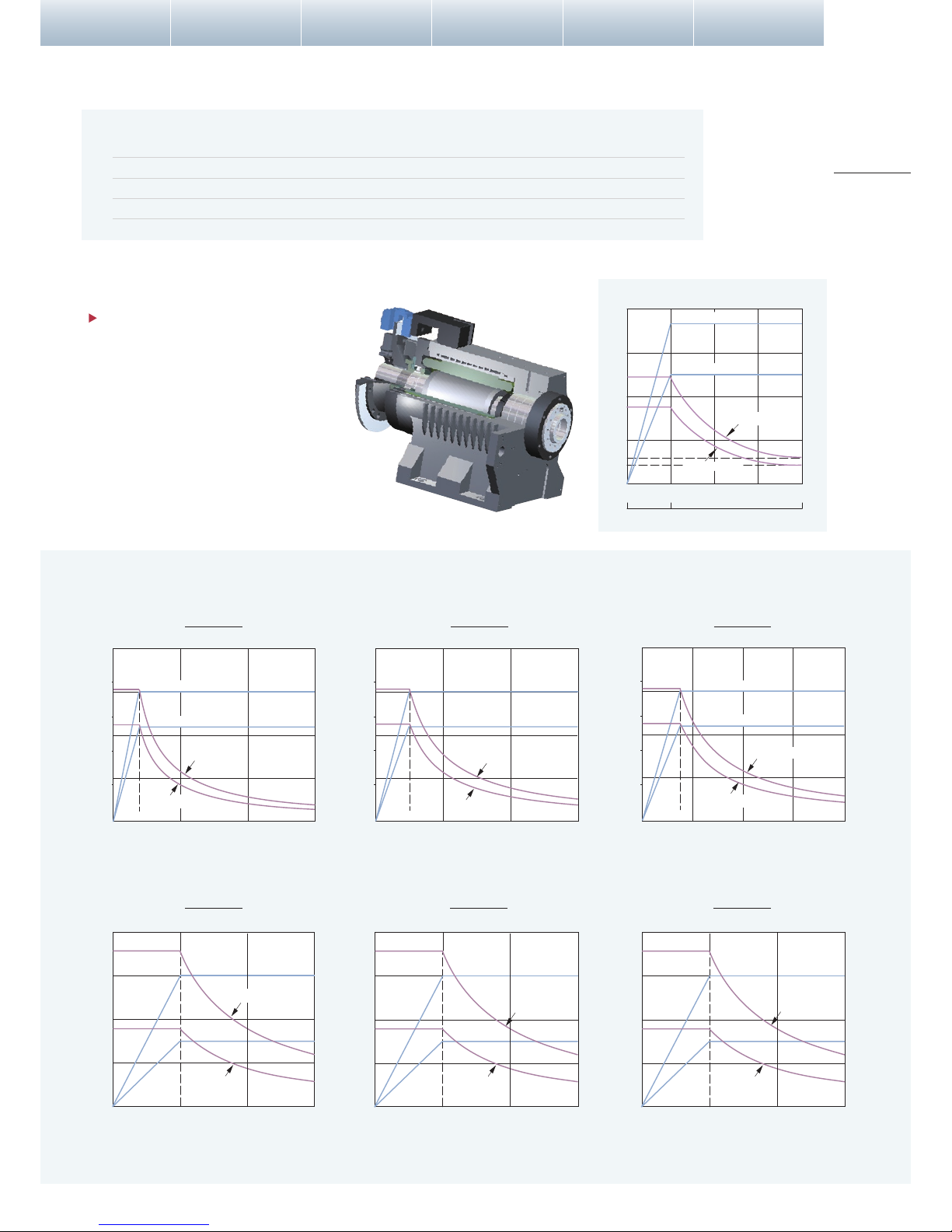
4
( Built-in spindle construction )
GLS-150 Spindle Acc. / Dec times
Chuck : 6" + hard jaws
Unit : sec.
RPM
Acc.
Dec.
1000 1500 2000 2500 3000 4000 5000 6000
1.3 1.6 1.8 2.2 2.6 3.6 5.2 7.3
1.0 1.2 1.6 2.0 2.5 3.1 4.1 4.8
6000rpm
1500
0
20
40
60
80
3000 4500
Spindle Speed
Torque
( N-m )
7.5 kW ( 30 min. )
5.5 kW ( cont. )
Torque ( cont. )
Torque ( 30 min. )
48
35
8
6
4
2
12
9
Constant OutputConstant Torque
Built-in Spindle Output
GLS-150 models are available with
built-in spindle motors, which eliminate
traditional belts and pulleys. This
advanced system provides faster
spindle response, reduces vibration
and power loss, which translate to
faster cycle times, higher accuracy, and
lowers maintenance costs.
( 6" CHUCK )
Spindle motor output
Performance Quailty Features Automation Dimensions Specications
Output
( kW )
Output
( kW )
Torque
( N-m )
Output
( kW )
Torque
( N-m )
Output
( kW )
Torque
( N-m )
Output
( kW )
Torque
( N-m )
Output
( kW )
Torque
( N-m )
Output
( kW )
Torque
( N-m )
287
143
7.5
80
160
240
320
0
500 1000 1500 rpm
5
10
15
20
287
143
7.5
80
160
240
320
0 500 1000 1500 rpm
5
10
15
20
287
143
7.5
80
160
240
320
0 500 1000 1500 rpm
5
10
15
20
15 kW ( 30 min. ) 15 kW ( 30 min. ) 15 kW ( 30 min. )
GLS-150
High-speed
GLS-200
High-speed
GLS-260
High-speed
GLS-150
Low-speed
GLS-200
Low-speed
GLS-260
Low-speed
191
140
750
11
0
50
100
150
200
250
2000 4000 6000 rpm
5
10
15
20
15 kW ( 30 min. )
11 kW ( cont. )
191
140
750
11
0
50
100
150
200
250
1500 3000 4500 rpm
5
10
15
20
191
140
750
11
0
50
100
150
200
250
1000 2000 3000 4000 rpm
5
10
15
20
Torque ( 30 min. )
Torque ( cont. )
11 kW ( cont. )
11 kW ( cont. )
11 kW ( cont. )
Torque ( 30 min. )
Torque ( 30 min. ) Torque ( 30 min. )
Torque ( cont. ) Torque ( cont. ) Torque ( cont. )
15 kW ( 30 min. )
11 kW ( cont. )
Torque ( 30 min. )
Torque ( cont. )
15 kW ( 30 min. )
11 kW ( cont. )
Torque ( 30 min. )
Torque ( cont. )
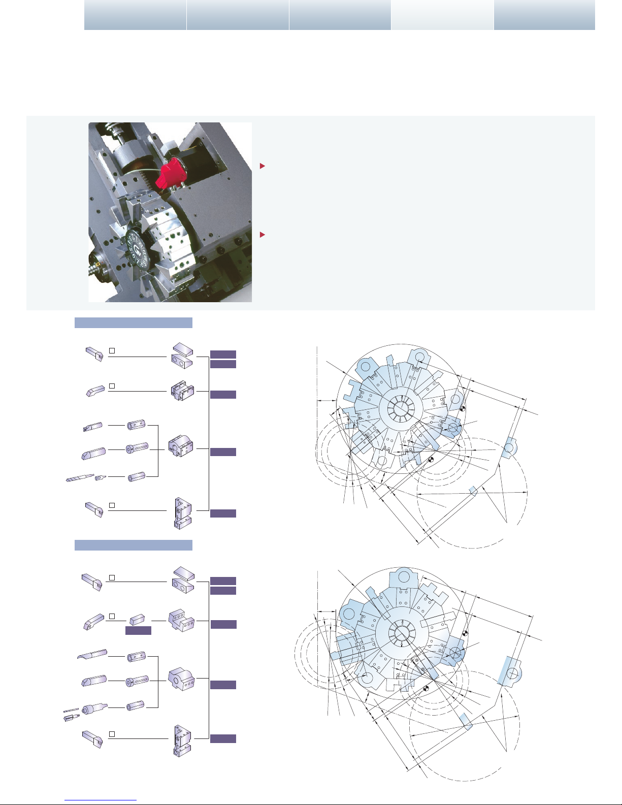
ADVANCED TURRET TECHNOLOGY
GLS Series Construction Spindle Turret Multi-Tasking
Unit: mm
A high-speed servo motor indexing system provides the 10 or
12-station turret with a 0.2 sec. indexing time. Large diameter high
precision curvic couplings and hydraulic clamping are used to enhance
tool indexing accuracy and turret disk rigidity.
The standard 10-staion turret clears 8" diameter work holding
devices without interference while the 12-station turret clears 6"
diameter devices.
1
4
7
1
6
6
8
5
3
2
7
8
5
4
2
3
9
10
10
11
12
9
X-axis stroke : 215
X-axis stroke : 215
165
15
190
35
10
Ø32
190
165
15
10
45
Ø470
Ø400
Max.turning Dia.
Spindle center line
69.9
45
35
165 40
190
20
X-axis stroke : 220
X-axis stroke : 220
165
40
10 190 20
78
6” Chuck
6” Chuck
8” Chuck
8” Chuck
10” Chuck
10” Chuck
6” Chuck
8” Chuck
10” Chuck
6” Chuck
8” Chuck
10” Chuck
10
42
Ø480
Ø40
66.8
Max.turning Dia.
Spindle center line
Ø400
Ø 32
Ø 40
CV-3045
CV-3090
CV-3093
CV-3091
CR-3075
CT-3046
CY-3006
CY-3031
CT-3045
CY-3007
Clamping Block
Clamping Block
O.D. Tools
O.D. Tools
O.D. Tools
O.D. Tools
O.D. Tools
O.D. Tools
I.D. Tools
I.D. Tools
I.D. Tools
I.D. Tools
Sleeve
Sleeve
Sleeve
Sleeve
Sleeve
Sleeve
Face Tool Holder
Face Tool Holder
I.D. Tool Holder
I.D. Tool Holder
Cut o- Tool Holder
Cut o- Tool Holder
CV-3046
Drill
Drill
25
25
25
20
20
20
Interference Diagram
Tooling System
Optional 10-Stations Turret
Tooling System Interference Diagram
Standard 12-Stations Turret
 Loading...