

Page 1
GTV14CDG
14" (34cm) COLOUR TELEVISION
WITH DVD PLAYER
OPERATION MANUAL
HELPLINE PHONE NUMBER 08708 730080
1
Page 2

Contents
CAUTION ................................................................................................................................ 3
IMPORTANT SAFEGUARDS (PREFITTED MAINS PLUGS) .................................................... 5
LOCATION OF CONTROLS ................................................................................................... 6
LOCATION OF REMOTE CONTROL UNIT ............................................................................. 7
OPERATING THE TELEVISION RECEIVER ............................................................................. 8
OPERATING WITH REMOTE CONTROL ............................................................................... 11
TELETEXT FUNCTION CONTROL ........................................................................................ 12
DVD PLAYER OPERATION .................................................................................................... 14
SPECIFICATION .................................................................................................................... 26
2
Page 3
CAUTION: TO REDUCE THE RISK OF ELECTRIC SHOCK. DO NOT REMOVE COVER (OR
BACK).
NO USER SERVICEABLE PARTS INSIDE. REFER SERVICING TO QUALIFIED SERVICE PERSONNEL.
The graphic symbols on the back cover of the set mean the following:
The lightn ing flash with arrowhead symbol withi n an equilateral trian gle is intended to alert the user to the presence of uninsulated "dangerous voltage" within
the product's enclosure that may be of sufficient magnitude to constitute a risk of
electric shock to persons.
The exclamation point within an equilateral triangle is intended to alert the user to
the presence of important operating and maintenance (servicing) instructions in
the literature accompanying the appliance.
WARNING : TO REDUCE THE RISK OF FIRE OR ELECTRIC SHOCK, DO NOT EXPOSE
THIS APPLIANCE TO RAIN OR MOISTURE.
INSTALLATION
LOCATE the receiver in the room where direct light does not strike the screen. Total darkness
or a reflection on the picture screen can cause eyestrain. Soft and indirect lighting is recommended for comfortable viewing.
ALLOW enough space between the receiver and the wall to permit proper ventilation.
AVOID excessive warm locations to prevent possible damage to the cabinet or component
failure.
CONNECTION
This TV receiver can be connected to AC: 230V~ 50Hz .
AUTOMATIC DEGAUSSING
All color television receivers are sensitive to magnetic influences, usually caused by either
moving the receiver from one place to another or using certain electrical appliances near the
receiver. This residual magnetism as it is called, sometimes causes distortion which gives rise
to "blotchy" areas of color in the picture. To avoid these effects the receiver incorporates an
automatic degaussing circuit which operates for a short while immediately each time the receiver is switched on using the mains switch. This circuit removes any residual magnetism in
the metal parts of the picture tube and therefore ensures that each time the receiver is switched
lifelike. If the set is moved or faced in a different direction, the mains switch must be switched
off at least 10 minutes in order that the automatic degaussing circuit operates properly.
3
Page 4

CAUTION
Never tamper with any components inside your set, or any other adjustment controls not
mentioned in this manual. All television receivers are high voltage instruments. Your PICTURE
TUBE is highly evacuated. If broken, glass fragments will be violently expelled. Scratching,
shipping or undue pressure is dangerous and should be avoided. When you clean up dust or
stick or a water drop on the PICTURE TUBE FACE or CABINET, the power cord should be pulled
out from the wall then wipe the receiver with a dry soft cloth. All "inside work" on your receiver
should be performed only by the Professional Service Personnel.
DANGER
LASER SAFETY
This unit employs an optical laser beam system in the CD
mechanism,designed with built in safeguards. Do not attempt
to disassemble, refer to qualified service personnel.
Exposure to this invisible laser light light beam may be harmful
to the human eye.
Invisible laser radiation when open
and inte rlock fai le d or defe at ed.
avoid direct exposure to laser beam.
THIS IS A CLASS-1 LASER PRODUCT. USE OF CONTROLS,
OR ADJUSTMENTS OR PROCEDURES OTHER THAN THOSE
SPECIFIED HEREIN, MAY RESULT IN HAZARDOUS LA-
SER LIGHT BEAM EXPOSURE.
Manufactured under license from Dolby Laboratories “Dolby”,”Pro Logic”and the double-D
symbol are trademarks of Dolby Laboratories. Confidential unpublished works.© 1992-1997
Dolby Laboratories,lnc.All rights reserved.
This product incorporates copyright protection technology that is protected by U.S.patents and
other intellectual property rights. Use of this copyright protection technology must be authorized
by Macrovision,and is intended for home and other limited viewing uses only unless otherwise
authorized by Macrovision.Reverse engineering or disassembly is prohibited.
4
Page 5
IMPORTANT SAFEGUARDS
PREFITTED MAINS PLUGS
For you convenience a mains plug has been fitted to this appliance. For your safety please
observe the following information.
1. Should the fuse in the plug fall remove the plug from the wall socket and replace the fuse with
a 3 Amp ASTA approved to BS 1362 fuse.
2. Never use the plug without the fuse cover fitted. Replacement fuse covers are available
from your dealer or most electrical retail outlets.
3. If the mains plug is out off the cable, rewire the replacement plug in accordance with
instruction give in this manual.
4. CAUTION: Under no circumstances should the discarded plug be inserted into the mains
socket. To prevent a shock hazard carefully dispose of the discarded plug.
Do not leave the plug lying around where children might see it.
WARNING: To prevent fire or shock hazard do not expose this unit to rain or moisture.
CAUTION:
DANGEROUS VOLTAGES EXIST INSIDE THIS UNIT DO NOT REMOVE COVER (OR
BACK).
NO USER SERVICEABLE PARTS INSIDE REFER SERVICING TO QUALIFIED SERVICE
PERSONNEL. DISCONNECT FROM MAINS SUPPLY WHEN NOT IN USE.
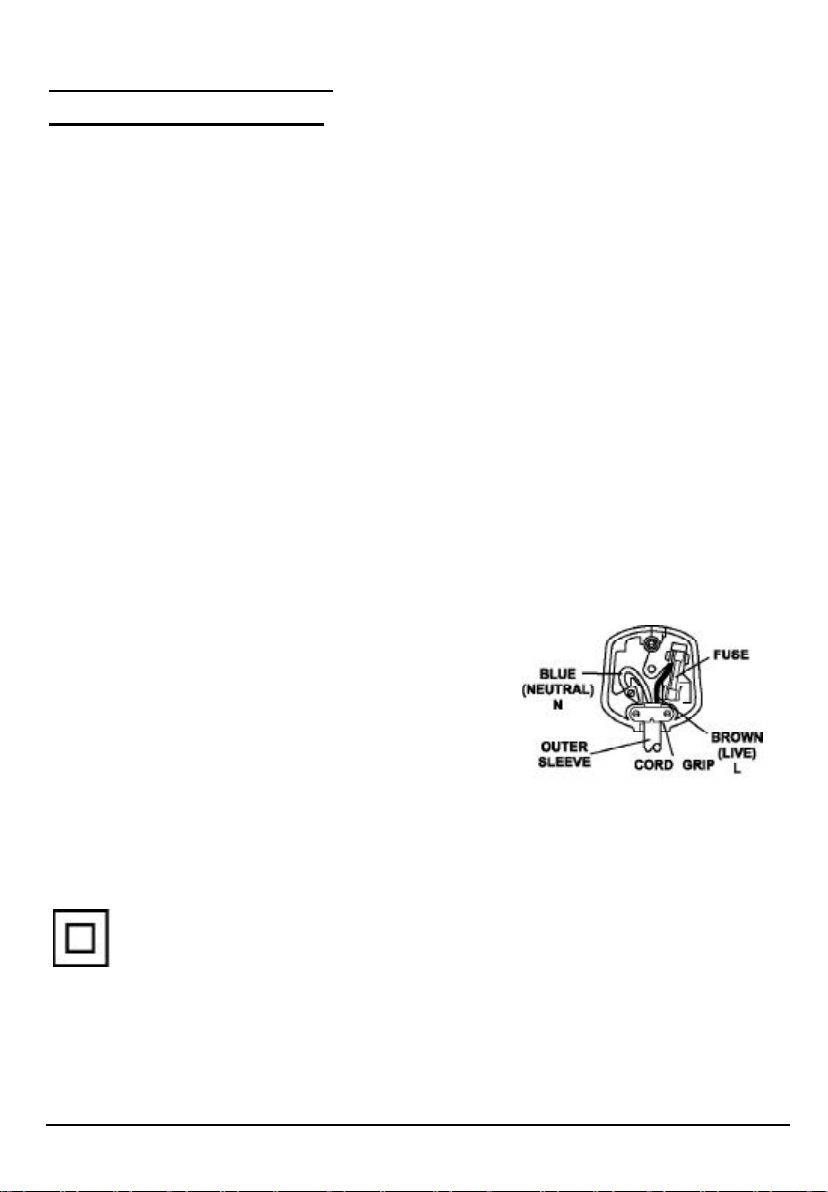
This wires in this mains lead are coloured in accordance with the following wiring codes:
Blue................................... Neutral
Brown................................... Live
This wires in this mains lead must be connected to
the terminals in the plug as follows:
Blue Wire........................... N or Black
Brown Wire.......................... L or Red
Only a 3 Amp fuse should be fitted in the plug or a 5 Amp fuse at the distribution board.
WARNING: UNDER NO CIRCUMSTANCES MUST THE LIVE OR NEUTRAL WIRES BE
CONNECTED TO THE EARTH TERMINAL IN A 3 - PIN MAINS PLUG.
This symbol means that this unit is double insulated. An earth connection is not required.
HELPLINE PHONE NUMBER 08708 730080
5
Page 6
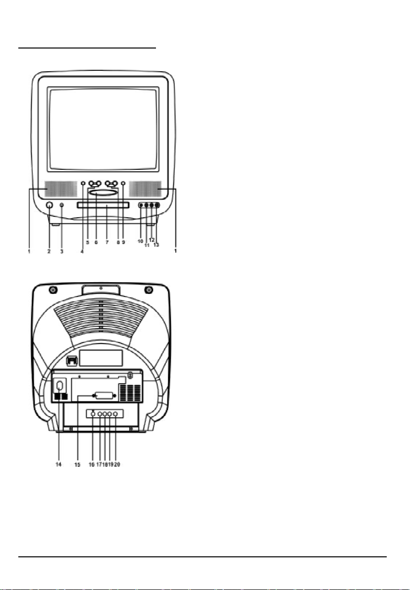
LOCATION OF CONTROLS
1. Speaker
2. Power Button
3. Remote Sensor
4. TV/AV/DVD Buttons
5. Channel Button
6. DVD Open/Play/Stop Button
7. DVD Loader
8. Volume Buttons
9. MENU Button
10. MIC INPUT
11. Front Video Input
12. Front Audio (L) Input
13. Front Audio (R) Input
14. 75 ohm Antenna
15. Scart counector
16. Audio digital Out Socket(for DVD only)
17. Audio out (R) for DVD
18. Audio out (L) for DVD
19. Video out for DVD
20. S-Video out for DVD
6
Page 7

REMOTE CONTROL UNIT
41. SLOW Button
42. CLEAR Button
43. REPEAT Button
44. DVD SUBTITLE Button
45. PAL/NTSC Button
46. Teletext Stop Button
47. Teletext Index Button
48. Teletext Mix Mode Button
49. Teletext/TV Mode Button
1. TV Button
2. STANDBY button
3. DISPLAY Button
4. MUTE Button
5. Numeric Buttons
6. SETUP Button
7. AUDIO Button
8. AVC (Karaoke)Button
9. TV CHANNEL / Buttons
10. Direction Up Button
11. Direction Left Button
12. Direction Down Button
13. PREV Button
14. Pause /STEP Button
15. PLAY Button
16. REPEAT (A-B) Button
17. STOP Button
18. DVD ZOOM Button
19. SEARCH Button
20. ANGLE Button
21. Teletext Enlarge Button
22. Teletext Conceal Button
23. TV System/Teletext Cancel Button
24. Teletext Time Display Button
25. DVD Button
26. OPEN/CLOSE Button
27. PP (TV Personal Preference) Button
28. TV/AV Button
29. Two Digital program button
30. + 10 Button
31. MENU (DVD) Button
32. MENU (TV) Button
33. Function(Karaoke)Button
34. VOLUME / Buttons
35. DVD ENTER Button
36. Direction Right Button
37. NEXT Button
38. SCAN Forward Button
39. SCAN Backward Button
40. PROGRAM Button
BATTERY INSTALLATION
• Insert two pcs "AAA"; "LR03" batteries (supplied) as illustrated and replace the battery cover.
7
Page 8
OPERATING THE TELEVISION RECEIVER
Connect your TV aerial to the aerial input socket located on the back of the TV.
Push the Main Power Switch, Power Indicator will be illuminated. After a few seconds the TV
screen will light up. Should white dots appear on the screen the TV will require tuning into the
available TV stations in your area.
Pre-setting the TV stations into the Memory
(Note: Preset tuning can only be carried out in TV Mode)
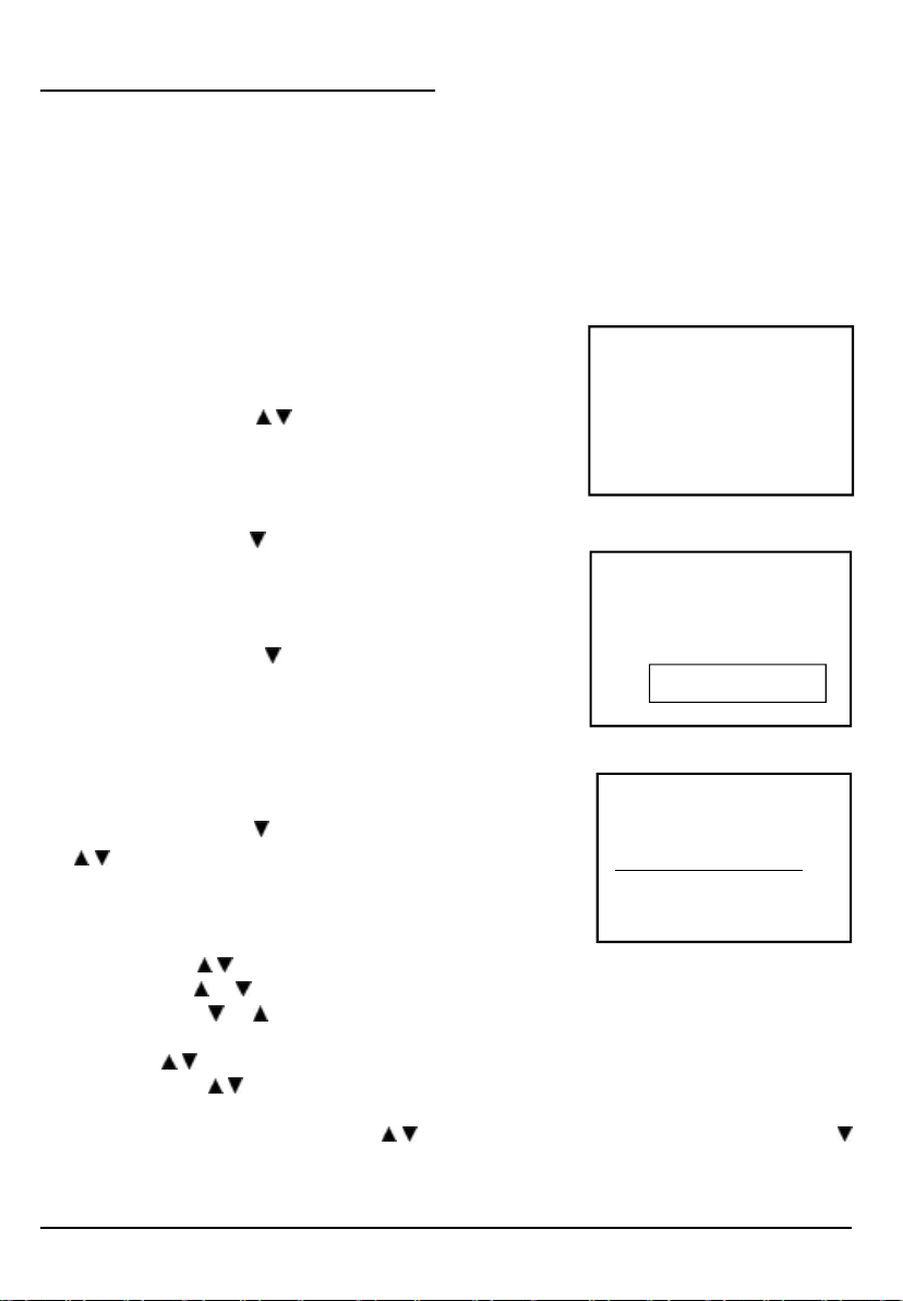
1. Press MENU button to main MENU.
2. Press the VOL button / to select TUNE mode
as shown in figure 1.
AUTO SEARCH
1. Press the CH button To select the AUTO SEARCH (auto
memory store) mode as shown in figure 2.
2. Press the VOL button to start the automatic scanning
processes, the on air stations will automatic store into
memory as shown in figure 3.
• When scanning is completed. the set will tune to lowest
program and show lowest program number on the screen.
• If want to stop auto search function, press menu button.
• Press the CH button to select the SKIP and press VOL
/ to select on or off,This function use for delete some
unwant channels.
SEARCH (manual)
1. Press MENU button.
2. Press the VOL / to select TUNE
3. Press the CH or button and select SEARCH.
4. Press the VOL or button to start searching up or down the frequency.
5. When a TV station is located, the station will show.
6. Press CH / button until Program shows.
7. Press the VOL / button and select which position.
To store the TV station i.e BBC1=1, BBC2=2 and so on.
8. To store the station, press the CH / button until Store shows. Now press the VOL
button to store the station.
Repeat 2 to 7 above and store the remaining TV channels in your area.
FIG .1
FIG .2
FIG .3
PICTURE TIMER SETUP TUNE
5
AUTO SEARCH
6
VHF - L
| | |
STOP MENU
8
Page 9

PICTURE
1. Press the MENU button to main MENU.
2. Press the VOL button / select the PICTURE mode .
3. Press the CH button / to select the BRIGHINESS / COLOR /
CONTRNST / SHARPNESS as show in figure 4.
4. Press the VOL button / to adjust the level of currently
selected item, The steps can be adjust from 0 ~ 63 .
TIMER
1. The TV can switch ON/OFF the power automatically by the following procedure.
2. Press the MENU button to main MENU.
3. Press the VOL button to select the TIMER mode, press the CH button to adjust the
colck time as shown in figure 5 .
1 7 0 0
1 7
3 0
1 7
4. Press the VOL button / to adjust the hour time _ _ : _ _ ;
Press the CH button to select the minute _ _ : _ _ ;
Press the VOL / to adjust the minute time _ _ : _ _ .
BRIGHTNESS 30
FIG .4
3
5. Continue press the CH and VOL button / to set the
ON TIME _ _ : _ _ . ON PROG. OFF TIME _ _ : _ _ .
• To make the timer function effective,The TV must set to
standby mode, After process is complected.
SETUP
1. Press the MENU button to main MENU.
2. Press the VOL button to select SETUP mode .
LANGUAGE
1. Press the CH button to select the language, as shown in
figure 6 .
2.Press the VOL button / to select the desire Languages.
BLUE BACK (blue back-ground)
Press the CH button to select the BLUE BACK ,press the VOL button to set the blue
back-ground ON / OFF.
9
6
CLOCK _ _ : _ _
5
FIG .5
ENGLISH
FIG .6
5
6
Page 10

OPERATING THE TELEVISION RECEIVER
CHANNEL SELECT AND VOLUME CONTROL
1) Press CH. / buttons to select TV station. (TV Mode Only)
0
Press CH." ", the program no. will
appear on the top rihgt corner and
change from higher no. to lower no.
2) Press VOL / to ADJUST sound level.
TV/AV/DVD Mode Button
• If video/audio input socket are in use, press AV/TV Mode button, "AV" will display on the top
right corner of the screen.
Press CH. " ", the program no. will
change from lower no. to higher no.
VOLUME
| | | |
99
• Press TV/AV/DVD button to turn on DVD. When DVD mode is selected please wait, the screen
will be dark as it will take a few seconds to show the "DVD" on the top right corner of the
screen.
TV AV DVD
10
Page 11

OPERATING WITH REMOTE CONTROL
TO SELECT TV STATION USING THE PROGRAM NUMBERS:
• Program Number Up and Down
Press the CH. " " or " " button to select a higher or lower program number..
• 0 - 9 Digital Button
To select TV stations using program numbers 0 - 9, selecting program number will be shown
in the right corner of the top of screen in green colour.
For example:
Press "9" digit button to select program "9".
• Two Digital Program Number
To select TV station using program numbers "10" - "99".
For example: selecting program 12
* Press the button "-/- "
*Then press the number "1" button, on screen will show "1-"
* Then press the number "2" button, channel "12" will show.
• PP Button (personal preference )
Press (PP) button to select the picture effect.
PP MILD STANDARD DYNAMIC
Stand-By Button ( )
• Press the " " button to switch on the picture and sound.
Mute Button
• Press the mute button to switch OFF the sound, press once again to switch ON the sound.
TV Mode Button
• Press the TV Mode button to select the TV mode .
TV/AV Mode Button
• Press the AV/TV mode Button to select AV mode,Press again back to TV mode.
DVD Mode Button
• Press the DVD Button to select DVD mode.(It need a few seconds to start the DVD)
NOTE:
• The transmit code of remote control is different between TV and DVD, before to use the
remote control hand set to control the TV, press the TV button ,to control the DVD, press
the DVD button, it is to make sure the transmit code is correct for TV and DVD,otherwise
some keys on the remote hand set will be no function.
11
Page 12

OPERATION WITH REMOTE CONTROL
TELETEXT FUNCTION CONTROL
Teletext - is an information system that displays text on your TV screen. Using the Teletext
information system you can select a page of information on a subject that is available in its list
of contents (index).
To Operate Teletext
1. Press the TV Mode Button
To select a TV station on which Teletext is being transmitted (check with a TV programme
guide).
2. Press the Teletext Button ( )
Using the list of contents (index) is display on the screen.
3. To select a Page of Teletext
Press the appropriate Digit button for the required Teletext page number.
The selected page number is displayed at the top left corner of the screen. The Teletext
page counter searches until the selected page number is located, so that the required
information is displayed on the screen.
4. Program + (CH )
Press the Program “ + “ button to set up to the next higher teletext page.
5. Program - ( CH )
Press the Program “ - “ button to set up the next lower teletext page.
6. Press the ( ) button to return the teletext page to page number 100.
To Exit Teletext
Press the TV Mode button , the previously selected TV station appears again on the screen.
Mix Mode Button ( )
• Press button " " to superimpose the text over the TV program on the screen.
• Press once again to return to Teletext page.
Enlarge Button ( )
• Press button " " to display top half of the page at double height text.
• Press again to display bottom half of the page.
• Press again to get full page at normal height text.
12
Page 13

OPERATION WITH REMOTE CONTROL
TELETEXT FUNCTION CONTROL
Stop Button ( )
More information may follow the page of Teletext you have selected, and it is automati
cally displayed after a short period of time.
• Press button " " to hold the page.
• Press again to resume automatic page changing.
Cancel Button ( x ) (System)
To switch between Teletext and TV programme.
• Press button " x" the TV programme appears.
• Press once again to return to the Teletext page.
Conceal Button ( ? )
Sometimes a Teletext page contains concealed information, for example, in a quiz or puzzle.
• Press button "?" to display the concealed information, press once more to clean.
To Display the Time ( ) (In TV Programme Mode)
• Press button " ", the current time is displayed in the top right corner of the screen (e.g.
21:00).
• Press the button again to remove the time display.
Note: The time can only be display when Teletext is available on the selected TV station.
To Select a Subcode Page
Subcode pages are subsections of long Teletext pages that can only be displayed on the
screen one section at a time.
• Select the required Teletext page.
• Press the " " button.
• Press a digit button (for the required subcode page).
• If the subcode page is not immediately available then press the "x" button to return to the TV
programme. When the subcode page becomes available, the subcode number is displayed
in the top left corner of the screen.
• Press the "x" button to display the subcode page.
13
Page 14

DVD PLAYER OPERATION
BASIC OPERATION
1. Press “TV/AV/DVD” button on the unit or press the DVD MODE direct key on the remote
handset to turn ON DVD.
2. Press “OPEN / CLOSE (EJECT)” button to load disc in disc tray.
3. Press “OPEN / CLOSE” button to close the tray.
• Hold the disc without touching either of its surfaces, position it with the printed title side
facing up.
PLAY DISCS
1. Press the OPEN/CLOSE Button on the front panel and load the Disc on the tray.
The label side should be facing upwards. For a Double-sided DVD Disc, put the disc with label
A/1 up.
2. Press the OPEN/CLOSE button again to close the tray and the disc will be loaded.
3. The Disc will be played automatically.
• If it is a DVD disc, it will show the Menu/Title Page on the screen.
• If it is a CD, it will play the first track directly.
4. Press the STOP Button if you want to stop the Disc playback You can resume playback by
pressing the PLAY button and it will start at the location where you have pressed stopped
(Resume Play).
5. Press the STOP Button twice to have the Disc really stopped.
|| (PAUSE)/ STEP
This function is applicable for DVD and CD audio.
• For DVD, the picture will freeze.
• For CD audio, it will become muted.
1. Press the ( || ) Button to pause play.
2. Press the PLAY Button again to resume Play.
DVD SETUP MODE
DVD setup mode can only be selected whilst in the DVD mode.
• Setup Mode provides menu for the configuration of SYSTEM SETUP,LANGUAGE SETUP,
KARAOKE SETUP ,VIDEO SETUP,SPEAKER SETUP,DIGITAL SETUP.
• Item selection in the SETUP menu is done by using the direction button and the ENTER button.
• To exit the SETUP Mode, press the SETUP button again or select the EXIT and press the
ENTER button.
14
Page 15

SYSTEM SETUP
In stop mode press SETUP button and highlight SYSTEM setup then press ENTER button to
confirm.
TO select the desired item by use the direction / , / button,then press the ENTER button to
confirm the selected item.
TV SYSTEM : NTSC
PAL(Default)
AUTO
SCREEN SAVER : ON (Default)
OFF
TV TYPE: 4:3 PS (Pan Scan)
4:3 LB (Letter Box)(Default)
16:9 (wide screen)
15
Page 16

v PASS WORD: _ _ _ _
The password option is initialized locked, and
you cannot set the ratings limit or change the
password. In order for the Ratings feature work,
the password mode must be turned on. If you
want to set the ratings limit, you will need to
enter the default password, which is 0000, then
press Enter to confirm. To change the password,
you will be prompted for the old password, then
be prompted for a new. Enter a 4-digit number
(this is your password).
RATING: NO ADULT
KID. SAFE
VIEW ALL(Default)
The Rating feature is a rating limit system, like movie ratings. It works with DVD discs that have
been assigned a rating. This helps you control the types of DVDs that your family watches.
• There are two rating options: NO ADULT and KID SAFE.
• Select the VIEW ALL option to cancel the rating limit.
The default setting is VIEW ALL.
Notes:
• If the password option is locked, you cannot set the ratings limit; the rating limit doe not work
when the password option unlocked.
v DEFAULT: RESTORE
Choose this option to resume all the setup op-
tions to default settings.
16
Page 17

LANGUAGE SETUP MENU
In stop mode press SETUP button and press the direction / button to highlight language setup
then press ENTER button to confirm.
OSD LANGUAGE
1. Press direction / button to highlight the OSD and press ENTER button,then press the
direction / button to select the desired OSD language.
• ENGLISH (Default)
• GERMAN
• SPANISH
• FRENCH
• PORTUGUESE
AUDIO LANGUAGE
1. Press direction / button to highlight the AUDIO and press the ENTER button,then press the
direction / button to select the desired AUDIO language.
• ENGLISH (Default)
• FRENCH
• SPANISH
• PORTUGUESE
• GERMAN
SUBTITLE LANGUAGE
1. Press direction / button to highlight the AUDIO and press the ENTER button,then press the
direction / button to select the desired AUDIO language.
• ENGLISH
• FRENCH
• SPANISH
• PORTUGUESE
• GERMAN
• OFF(Default)
17
Page 18

MENU LANGUAGE
1. Press direction / button to highlight the SUBTITLE and press the ENTER button,then press
the direction / button to select the desired SUBTITLE language.
• ENGLISH(Default)
• FRENCH
• SPANISH
• PORTUGUESE
• GERMAN
VIDEO SETUP
In stop mode press SETUP button and press the direction / button to highlight VIDEO setup
then press ENTER button to confirm.
v BRIGHTNESS
Use the Up and Down arrow button to move the scroll and adjust the brightness.
v CONTRAST
Use the Up and Down arrow button to move the scroll and adjust the contrast.
18
Page 19

v HUE
Use the Up and Down arrow button to move the scroll and adjust the hue.
v SATURATION
Use the Up and Down arrow button to move the scroll and adjust the saturation.
19
Page 20

KARAOKE SETUP
Quick setup is also available whilst the disc is playing. Press and hold the KARAOKE FUNCTION
button on the remote. The ECHO / MIC / KEY will be shown cyclically in the display. When the
correct function to be altered is shown release the FUNCTION button and press the KARAOKE
“ - “ and “ + “ buttons to alter the shown function. This new change will be memorised when no
further buttons are pressed and the TV screen returns to normal operation.
In stop mode press SETUP button and highlight KARAOKE setup then press ENTER button to
confirm.
ECHO : 8
6
4 (Default)
2
OFF
• Use the Up and Down arrow button to move the
scroll and adjust the echo.
MIC VOL : 8
6
4 (Default)
2
OFF
• Use the Up and Down arrow button to move the
scroll and adjust the microphone vol ume.
KEY : 8
+4
+2
0 (Default)
-2
-4
b
• Use the Up and Down arrow button to move the
scroll and adjust the key.
20
Page 21

SPEAKER SETUP
In stop mode press SETUP button and highight SPEAKER SETUP thress ENTER button to confirm.
DOWN MIX: LT/RT
STEREO (Default)
• LT / RT:
Choose this setting, it will be sound like in a movie theatre if the original movie was recorded
from encoded in the ProLogic Dolby Digital format.
DIGITAL SETUP
AUDIO OUT: SPDIF/RAW(Default)
SPIF/PCM
• SPDIF/ RAW: Choose this setting if your DVD player is connected to a power amplifier with a
coaxial cable or an optical cable; When playing a disc recorded with Dolby Digital, DTS and
MPEG audio formats, the corresponding digital signals will be output from the Coaxial
Output jack or Optical Output jack. This player’s digital output jacks are designed for a
connection to a Dolby Digital, DTS , or MPEG receiver or decoder.
21
Page 22

• SPDIF / PCM: Choose this setting if your DVD player is connected to a 2-channel digital stereo
amplifier; When playing a disc recorded with Dolby Digital and MPEG audio formats, audio
signals will be modulated into a 2-channel PCM signal, and it will be output from the Coaxial
Output jack or Optical Output jack.
DYNAMIC RANGE: FULL
6/8
4/8(Default)
2/8
OFF
• DYNAMIC RANGE: When “LINE OUT” is selected, choose this setting to adjust the line out
ratio and get different effect. If adjusting to FULL, the audio signal peak value will be the
minimum; while adjusting to OFF, maximum.
NOTE:
This option will be validated when the DOWNMIX OFF.
22
Page 23

DVD Menu
The DVD Menu Play function is only applicable for DVD movie. User can access the Casting
information, Production History, Movie Introduction etc. directly through this function.
1. Press the DVD MENU Button on the remote controller to enter the Root Menu.
2. Use the direction button ( / , / ) or input the item index through the Number keys (0-9)
to do the selection.
3. Press ENTER to confirm the selection.
Au dio
This function is applicable for DVD and CD audio but with different effects.
• Pressing the AUDIO Button will change the Audio channel.
Note:
When AVC is on this button is no function.
SCAN / SEARCH
This function is applicable for DVD and CD audio but with different effects. The FAST FORWARD
key and FAST BACKWARD key are used to achieve fast play function.
• For DVD , there are 5 different levels of speed (x2, x4,x8, x20) available. Press the FAST key
to cycle speed.
• For CD audio, the FORWARD/BACKWARD will play at high speed.
Note : Press PLAY Button at any stage will resume to normal speed.
This function is not available for CD-G.
PREV./NEXT
During playback, press one of the PREV./NEXT buttons (PREVIOUS button and NEXT button)
• When the PREV. button is pressed once, playback returns to the beginning of the PREVIOUS playing chapter or track.
• When the NEXT button is pressed once, playback starts at the beginning of next chapter or
track.
Slow
The Slow Forward is only available for DVD. There are 6 steps of slow motion speed; 1/2, 1/3,
1/4, 1/5,1/6,1/7. Press button to cycle playback speeds.
Note : Press Play Key to resume normal playback speed.
This function is not available for CD-G.
Repeat Mode
This function is available for DVD and CD audio but with different effects.
• For DVD disc playback, user can choose to repeat the current chapter,the current title or disc.
Subsequent key press of the REPEAT key can change between these three options.
• For CD, user can choose to repeat the current track or the whole disc (Repeat All). Subsequent key press of the REPEAT key can change between these two options.
23
Page 24

Repeat AB
User can specify the repeating interval by marking the starting point and the end point.
1. Press the REPEAT AB Button to mark the starting point. (Playback will continue).
2. Press the REPEAT AB Button to mark the end point. (The marked part will be repeated
automatically)
Note : Press the REPEAT AB Button during repetition will disable the Repeat mode.
This function is not available for CD-G.
Subtitle
This function is only available for DVD disc. It can change the subtitle language shown on the
screen.
Note : Number of subtitle available depends on the DVD disc.
This function is not available for CD-G.
Angle
Some discs may have multiple viewing angles during production. Use the ANGLE button to
select the viewing angle shown on the screen.
Note : The number of Angles of View depends on the Disc.
Search
The user can access a specific location or a specific track by keying in the target time or the
track number.
1. Press the SEARCH Button to enter to search mode .
2. Input the target time to the number button (0~9) and press the ENTER button. The player will
jump to the target Location immediately.
Display
This function is to show the time and status information on the screen.
Resume Play
This function is in playback mode, when the STOP Button is pressed once, the player will
enter the Resume Play mode. At this time, if the PLAY Button is pressed, the player will resume
playback at the location where the STOP Button is pressed. If the STOP button is pressed a
second time,resume mode cancels.
Zo om
This function is enlarge or reduce a still picture or a moving picture by pressing the ZOOM
button to select the levels of zooming (2,3,4,1/2,1/3,1/4).
NOTE: Use the direction buttons ( / , / ) to navigate within the image.
This function is not available for CD-G.
24
Page 25

AVC(Auto vocal cut)
In some CD-G disc record format R channel is record original singer sound, L channel is record
music,when AVC is select to ON the original singer sound will be cut automatically while the user
is singing.
Function
Press the button to select the MIC VOL,ECHO ,KEY functions then press the direction button (
/ ) to adjust the desired level.
Picture CD
Load a picture CD into the tray it the disc can be identified,the player will start showing the picture
(JPG) one by one (slide show).
Operation
During Slide Show Mode: -
• Press the STOP Button will shift to the Digest Mode in which 6 pictures will be shown on the
screen each time.
• Press the PAUSE Button will freeze the screen so that the current picture can be held for a long
time. To resume the slide show mode, press PLAY Button.
• Press the NEXT Button on the remote controller to skip the next picture.
• Press the PREVIOUS Button on the remote controller to repeat the current picture.
25
Page 26

SPECIFICATION
TV SECTION
Receiving Channels
VHF
L
VHF
H
UHF CH 21- 69
Tuner Type 100 Program Memoryl ,VS TUNING
DVD SECTION
Laser Wave length 655nm
Laser power : Class 1
Signal System PAL / NTSC output
Digital audio output Coaxial digital output; pin jack
S-video Y output level 1Vp-p (75 Ohm);
C output level 0.300Vp-p (75 Ohm) (PAL),
Headphone
Stereo in DVD mode
Mono in TV mode
CH 2 - 4
CH 5 - 12
0.286Vp-p (75 Ohm) (NTSC)
GENERAL SECTION
AC Power Input 230V ~ 50 Hz
AC Power Consumption 74 W
Speaker 3 x1.5 ” 8ohm x 2
Audio Output 1.8 W + 1.8 W
Dimensions W390 x H420 x D411(mm)
Net Weight 13.5 Kg
Region coding: All DVD discs are coded by the sales territory. Please note the player is factory
set to region 2 coding (UK and Europe) and cannot be changed. Therefore discs purchased
outside of UK or Europe cannot be played. This is in compliance with the DVD patent requirements.
26
 Loading...